Table of Contents
Advertisement
Advertisement
Table of Contents
Troubleshooting

Related Manuals for Valleylab SurgiStat II-20


Summary of Contents for Valleylab SurgiStat II-20
- Page 1 User’s Guide SurgiStat™ II-20 Electrosurgical Generator...
- Page 2 This manual and the equipment it describes are for use only by qualified medical professionals trained in the particular technique and surgical procedure to be performed. It is intended as a guide for using the Valleylab SurgiStat™ II-20 electrosurgical generator only. Additional technical information is available in the SurgiStat™...
- Page 3 Caution Indicates a hazardous situation which, if not avoided, may result in minor or moderate injury. Important Indicates an operating tip or Notice maintenance suggestion. Indicates a hazard which may result in product damage. SurgiStat II-20 User’s Guide...
-
Page 4: Table Of Contents
Performance Checks Chapter 4. Using the SurgiStat II Inspecting the Generator and Accessories Setup Safety Setting Up Preparing for Monopolar Surgery Applying the Patient Return Electrode Connecting Accessories Preparing for Bipolar Surgery Activation Safety Activating the Unit SurgiStat II-20 User’s Guide... - Page 5 Voltage Transients (Emergency Generator Mains Transfer) Electromagnetic Compatibility (IEC 60601-1-2 and IEC 60601-2-2) Output Characteristics Maximum Output for Bipolar and Monopolar Modes Output Power Curves Monopolar Cut Curves Monopolar Coag Curves 8-11 Bipolar Curves 8-14 Chapter 9. Warranty SurgiStat II-20 User’s Guide...
-
Page 6: List Of Figures
Figure 8-12. Output power vs. generator settings for Fulgurate mode 8-13 Figure 8-13. Output power vs. impedance for Bipolar mode 8-14 Figure 8-14. Peak voltage vs. power setting for Bipolar mode 8-14 Figure 8-15. Output power vs. generator settings for Bipolar mode 8-15 SurgiStat II-20 User’s Guide... - Page 7 • Components and accessories • Safety Caution Read all warnings, cautions, and instructions provided with this generator before using. Read the instructions, warnings, and cautions provided with electrosurgical accessories before using. Specific instructions are not included in this manual. SurgiStat II-20 User’s Guide...
-
Page 8: Key Features
Valleylab electrosurgical generators, patient return electrodes, and active accessories are designed to work as a system. Valleylab offers a selection of patient return electrodes and electrosurgical instruments that are fully compatible with this generator. When considering other manufacturer’s patient return electrodes and/or active accessories, customers should seek detailed user instructions and warning information from the manufacturer. -
Page 9: Components And Accessories
It is also important that you read, understand, and follow the instructions for use in this user’s guide. SurgiStat II-20 User’s Guide... -
Page 10: Warnings
The higher the current flow, and the longer the current is applied, the greater the possibility of unintended thermal damage to tissue, especially during use on small structures. SurgiStat II-20 User’s Guide... - Page 11 Potential for alternate site burns increases if the return electrode is compromised. Valleylab recommends the use of split-plate patient return electrodes and Valleylab generators with a contact quality monitoring system. Do not wrap the accessory cords or patient return electrode cords around metal objects.
-
Page 12: Cautions
When activating the unit, do not allow direct skin contact between the patient and the physician. Remove any loose fitting jewelry from the patient before activation. SurgiStat II-20 User’s Guide... - Page 13 1. U.S. Department of Health and Human Services. National Institute for Occupational Safety and Health (NIOSH). Control of Smoke from Laser/Electric Surgical Procedures. HAZARD CONTROLS, Publication No. 96-128, September, 1996. SurgiStat II-20 User’s Guide...
- Page 14 SurgiStat II-20 User’s Guide...
-
Page 15: Chapter 2. Controls, Indicators, And Receptacles
C h a p t e r Controls, Indicators, and Receptacles This section describes the front and rear panels, including all controls, indicators, receptacles, the fuse drawer, and ports. SurgiStat II-20 User’s Guide... -
Page 16: Front Panel
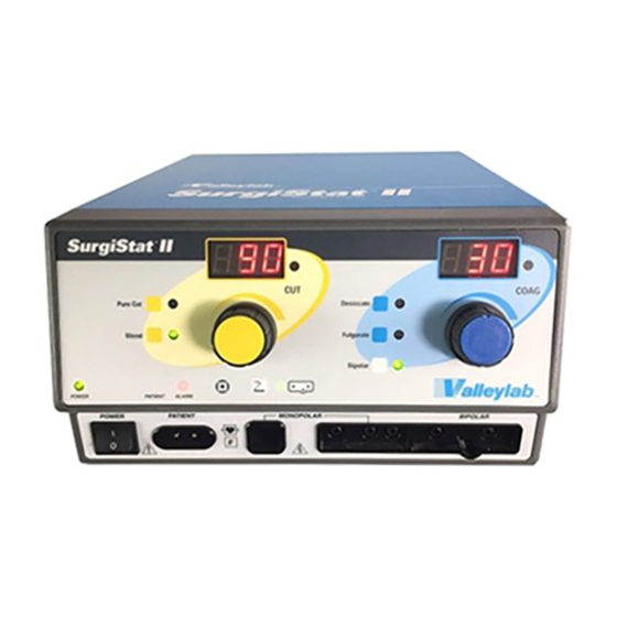
Front Panel Front Panel Figure 2-1. Layout of controls, indicators, and receptacles on the front panel SurgiStat II-20 User’s Guide... -
Page 17: Cut And Blend Controls
Blend Selector When pressed, selects the Blend mode. Cut and Blend Power Control Dial Increases or decreases the Cut or Blend Indicator Blend power output in increments of Illuminates when one watt. Blend mode is selected. SurgiStat II-20 User’s Guide... -
Page 18: Coag And Bipolar Controls
Bipolar Selector When pressed, Coag and Bipolar Power Control Dial selects the Bipolar Increases or decreases the Coag or mode. Bipolar power output in increments of one watt. Bipolar Indicator Illuminates when Bipolar mode is selected. SurgiStat II-20 User’s Guide... -
Page 19: Indicators
Selector When pressed, Split-Plate Patient Return Single-Plate Patient Return switches between Electrode Indicator Electrode Indicator monopolar and Illuminates when the system Illuminates when the system bipolar foot control. detects a split-plate. detects a single-plate. SurgiStat II-20 User’s Guide... -
Page 20: Power Switch And Receptacles
Receptacle Accepts standard three-pin Patient Return Electrode handpieces. Connect Receptacle handswitching accessories. Accepts a standard patient return electrode plug. Monopolar Footswitching Receptacle Accepts cables or adapters equipped with standard (Bovie #12) active plugs. Connect footswitching accessories. SurgiStat II-20 User’s Guide... -
Page 21: Rear Panel
AC mains power to monopolar and bipolar frequency, current, and the unit. activation. Use only a Valleylab power consumption. monopolar footswitch with the SurgiStat II-20 generator. Use of an incompatible footswitch may cause unexpected output. -
Page 22: Symbols On The Front Panel
Footswitch (on the selector button) Bipolar footswitch control Power Switch and Handpiece Connectors Read instructions before use Type CF equipment RF isolated – patient connections are isolated from earth at high frequency Caution – high voltage SurgiStat II-20 User’s Guide... -
Page 23: Symbols On The Rear Panel
Symbols on the Rear Panel Symbols on the Rear Panel Symbols Description Equipotential ground stud Nonionizing radiation Volume control Danger Explosion risk if used with flammable anesthetics Monopolar footswitch Read instructions before use SurgiStat II-20 User’s Guide... - Page 24 2-10 SurgiStat II-20 User’s Guide...
-
Page 25: Chapter 3. Getting Started
C h a p t e r Getting Started This section includes the following information: • Initial inspection • Installing the unit • Checking unit functions • Testing unit performance SurgiStat II-20 User’s Guide... -
Page 26: Initial Inspection
Connect a two-pedal footswitch to the appropriate footswitch receptacle on the back of the unit. Use only a Valleylab footswitch with the SurgiStat II-20 generator. Although other types of footswitches may fit, they may not be compatible. -
Page 27: Checking The Patient Return Electrode Alarm
Press the Cut pedal on the footswitch. Verify that the Cut and Blend Activation Indicator illuminates and that the system generates the Cut activation tone. While activating the Cut mode, rotate the volume control over the full range to verify that the sound is audible throughout the range. SurgiStat II-20 User’s Guide... -
Page 28: Checking Monopolar Mode (With Handswitch)
The testing should include checking all modes of operation for proper function and power output. For a detailed description of performance testing procedures, refer to the SurgiStat II Electrosurgical Generator Service Manual. SurgiStat II-20 User’s Guide... -
Page 29: Chapter 4. Using The Surgistat
• Activating the unit Caution Read all warnings, cautions, and instructions provided with this generator before use. Read the instructions, warnings, and cautions provided with electrosurgical accessories before use. Specific instructions are not included in this manual. SurgiStat II-20 User’s Guide... -
Page 30: Inspecting The Generator And Accessories
If the patient has an implantable cardioverter defibrillator (ICD), contact the ICD manufacturer for instructions before performing an electrosurgical procedure. Electrosurgery may cause multiple activation of ICDs. SurgiStat II-20 User’s Guide... - Page 31 • In addition, place patient return electrodes according to the manufacturer’s instructions. Potential for alternate site burns increases if the return electrode is compromised. Valleylab recommends the use of split-plate patient return electrodes and Valleylab generators with a contact quality monitoring system. Caution Do not stack equipment on top of the generator or place the generator on top of electrical equipment.
-
Page 32: Setting Up
Verify that the generator is off by pressing the power switch Off (O). Place the generator on a stable flat surface, such as a table, platform, or Valleylab cart. Carts with conductive wheels are recommended. For details, refer to the procedures for your institution or to local codes. -
Page 33: Connecting Accessories
If using a footswitch activated device, connect an appropriate Valleylab footswitch to the Footswitch Connecting Socket on the rear of the unit. Use only a Valleylab footswitch with the SurgiStat II-20 generator. Use of an incompatible footswitch may cause unexpected output. -
Page 34: Activation Safety
Consult the pacemaker manufacturer or hospital Cardiology Department for further information when use of electrosurgical appliances is planned for patients with cardiac pacemakers. SurgiStat II-20 User’s Guide... - Page 35 1. U.S. Department of Health and Human Services. National Institute for Occupational Safety and Health (NIOSH). Control of Smoke from Laser/Electric Surgical Procedures. HAZARD CONTROLS, Publication No. 96-128, September, 1996. SurgiStat II-20 User’s Guide...
-
Page 36: Activating The Unit
When using a Valleylab generator or patient return electrode during these types of surgical procedures the user should seek written guidance from the manufacturer of the active accessory regarding the currents and duty cycles that can be expected as well as detailed user instructions. - Page 37 Monopolar Cut or Blend modes yellow button handswitching yellow pedal pencil footswitch Desiccate or blue button handswitching Fulgurate modes blue pedal pencil footswitch Bipolar Any Bipolar yellow (Cut) or blue footswitch (Coag) pedal SurgiStat II-20 User’s Guide...
- Page 38 4-10 SurgiStat II-20 User’s Guide...
-
Page 39: Chapter 5. Maintaining The Surgistat
C h a p t e r Maintaining the SurgiStat II This section covers the following topics: • Cleaning • Periodic inspection • Fuse replacement SurgiStat II-20 User’s Guide... -
Page 40: Cleaning
Cleaning Valleylab recommends that you complete periodic inspection and performance testing. Perform inspections and performance testing every six months. A qualified biomedical technician should conduct this testing to ensure that the unit is operating effectively and safely. Cleaning After each use, clean the unit. -
Page 41: Fuse Replacement
Insert the fuse drawer into the Power Cable Receptacle. Use the following fuses: Surg II-20 110–120 V Amps 5.0 A Type Slow Blow Size 5 x 20 mm SurgiStat II-20 User’s Guide... - Page 42 SurgiStat II-20 User’s Guide...
-
Page 43: Chapter 6. Troubleshooting
C h a p t e r Troubleshooting This section includes error code descriptions and actions to take to resolve them. SurgiStat II-20 User’s Guide... -
Page 44: General Troubleshooting Guidelines
Step 1. display) 4. If the alarm number reappears, record the number and call the Valleylab Service Center. Cut and Coag buttons activated The unit does not allow simultaneous activation of the cut simultaneously (pencil or footswitch) and coagulation modes. - Page 45 4. If alarm number reappears upon restarting the unit, record the number and call the Valleylab Service Center. Internal pulse width measurement 1. Turn unit off.
- Page 46 SurgiStat II-20 User’s Guide...
-
Page 47: Chapter 7. Repair Policy And Procedures
C h a p t e r Repair Policy and Procedures Refer to this section for information on • The manufacturer’s responsibility • Returning the generator for service • Returning circuit boards • Finding service centers SurgiStat II-20 User’s Guide... -
Page 48: Responsibility Of The Manufacturer
Returning the Generator for Service Before you return the generator, call your Valleylab representative for assistance. If instructed to send the generator to Valleylab, first obtain a Return Authorization Number. Then, clean the generator and ship it to Valleylab for service. -
Page 49: Clean The Generator
Return Authorization Number. Ship the generator, prepaid, to the Valleylab Service Center. Service Center For a complete list of service centers worldwide, please refer to the Valleylab website: http://www.valleylab.com/valleylab/international/service-world.html SurgiStat II-20 User’s Guide... - Page 50 SurgiStat II-20 User’s Guide...
-
Page 51: Chapter 8. Technical Specifications
All specifications are nominal and subject to change without notice. A specification referred to as “typical” is within ± 20% of a stated value at room temperature (25° C / 77° F) and a nominal input power voltage. SurgiStat II-20 User’s Guide... -
Page 52: Performance Characteristics
500 Ω load), the generator is suitable for activation times of 10 seconds on, 30 seconds off for one hour. Dimensions and Weight Width 26 cm (10.25 in.) Depth 30.5 cm (12 in.) Height 15.2 cm (6 in.) Weight < 6.5 kg (< 14 lbs) SurgiStat II-20 User’s Guide... -
Page 53: Operating Parameters
Alarm tones meet the requirements for IEC 60601-2-2. Activation Tone Volume (adjustable) 45 to 65 dBA Frequency Cut: 1 kHz Blend: 1 kHz Desiccation: 2 kHz Fulguration: 2 kHz Bipolar: 2 kHz Duration Continuous while the generator is activated SurgiStat II-20 User’s Guide... -
Page 54: Patient Return Electrode Sensing
• The red LED alarm indicator remains illuminated until the condition that caused the alarm is corrected. • Activation attempts during an alarm condition result in an audio alarm and the alarm indicator flashes. SurgiStat II-20 User’s Guide... -
Page 55: Low Frequency (50-60 Hz) Leakage Current
(additional tolerance) Standards and IEC Classifications The SurgiStat II-20 generator meets all pertinent clauses of the IEC 60601-1 second edition and IEC 60601-2-2 third edition. Class I Equipment (IEC 60601-1) Accessible conductive parts cannot become live in the event of a basic insulation failure because of the way in which they are connected to the protective earth conductor. -
Page 56: Type Cf Equipment (Iec 60601-1)/Defibrillator Proof
Liquid Spillage (IEC 60601-2-2 Clause 44.3) The SurgiStat II-20 generator enclosure is constructed so that liquid spillage in normal use does not wet electrical insulation or other components which, when wetted, are likely to adversely affect the safety of the equipment. -
Page 57: Output Characteristics
7.7 ± 20% Ω Bipolar 30 W @ 200 520 kHz ± 50 32 kHz ± 5 kHz 2.0 kV 6.9 ± 20% * An indication of a waveform’s ability to coagulate bleeders without a cutting effect SurgiStat II-20 User’s Guide... -
Page 58: Output Power Curves
Figure 8-1 . Output power vs. impedance for Pure Cut mode Load Resistance (ohms) Figure 8-2. Peak voltage vs. power setting for Pure Cut mode Output Power Setting (watts) SurgiStat II-20 User’s Guide... - Page 59 Output Power Curves Figure 8-3. Output power vs. generator settings for Pure Cut mode 100 105 110 115 120 Generator Setting Figure 8-4. Output power vs. impedance for Blend mode Load Resistance (ohms) SurgiStat II-20 User’s Guide...
- Page 60 Output Power Curves Figure 8-5. Peak voltage vs. power setting for Blend mode Output Power Setting (watts) Figure 8-6. Output power vs. generator settings for Blend mode Generator Setting 8-10 SurgiStat II-20 User’s Guide...
-
Page 61: Monopolar Coag Curves
These measurements were taken using short (< 0.5 meter) leads. Figure 8-7. Output power vs impedance for Desiccate mode Load Resistance (ohms) Figure 8-8. Peak voltage vs. power setting for Desiccate mode Output Power Setting (watts) SurgiStat II-20 User’s Guide 8-11... - Page 62 Output power vs. generator settings for Desiccate mode 10 15 20 25 30 35 40 45 50 55 60 65 70 75 80 Generator Setting Figure 8-10. Output power vs. impedance for Fulgurate mode Load Resistance (ohms) 8-12 SurgiStat II-20 User’s Guide...
- Page 63 Output Power Curves Figure 8-11. Peak voltage vs. power setting for Fulgurate mode Output Power Setting (watts) Figure 8-12. Output power vs. generator settings for Fulgurate mode Generator Setting SurgiStat II-20 User’s Guide 8-13...
-
Page 64: Bipolar Curves
Output Power Curves Bipolar Curves Figure 8-13. Output power vs. impedance for Bipolar mode Load Resistance (ohms) Figure 8-14. Peak voltage vs. power setting for Bipolar mode Output Power Setting (watts) 8-14 SurgiStat II-20 User’s Guide... - Page 65 Output Power Curves Figure 8-15. Output power vs. generator settings for Bipolar mode Generator Setting SurgiStat II-20 User’s Guide 8-15...
- Page 66 8-16 SurgiStat II-20 User’s Guide...
-
Page 67: Chapter 9. Warranty
This warranty does not apply to any product, or part thereof, which has been repaired or altered outside Valleylab’s factory in a way so as, in Valleylab’s judgment, to affect its stability or reliability, or which has been subjected to misuse, neglect, or accident. - Page 68 Valleylab. Valleylab neither assumes nor authorizes any other person to assume for it any other liability in connection with the sale or use of any of Valleylab’s products. Notwithstanding any other provision herein or in any other document or communication, Valleylab’s liability with respect to this agreement and products...
Need help?
Do you have a question about the SurgiStat II-20 and is the answer not in the manual?
Questions and answers