Table of Contents
Advertisement
Quick Links
Advertisement
Table of Contents

Related Manuals for LEGRAND Keor MOD RI


Summary of Contents for LEGRAND Keor MOD RI
- Page 1 Keor MOD RI Installation and maintenance manual Part. LE14375AA-04/23-01 GF...
- Page 2 Keor MOD RI ENGLISH...
-
Page 3: Table Of Contents
Keor MOD RI Table of Contents 1. Introduction Purpose of the manual Symbols in the manual Where and how to keep the manual Update of the manual Manufacturer’s liability and guarantee 1.5.1 Guarantee terms 1.5.2 Extension of the guarantee and maintenance contracts Copyright 2. - Page 4 Table of Contents 5. Configuration and start-up Pre-start-up checks Start-up procedure Turning off the UPS 6. Maintenance Preventive maintenance Periodical checks Ordinary maintenance 6.3.1 Hot-swap procedure for the replacement of power modules 6.3.2 Installation/replacement of power modules with the UPS in maintenance bypass mode 6.3.2.1 Setting the UPS in maintenance bypass mode 6.3.2.2 Installation/replacement of power modules 6.3.2.3 Exit the UPS from the maintenance bypass mode...
-
Page 5: Introduction
The purpose of this manual is to provide the skilled technician (see paragraph 2.2.1) with instructions for safely installing the Keor MOD RI UPS, also called “equipment” in the rest of the manual and carry out ordinary maintenance procedures. Extraordinary maintenance operations are not dealt with because they are the sole preserve of the LEGRAND Technical Support Service. -
Page 6: Update Of The Manual
The guarantee terms may vary depending on the country where the UPS is sold. Check the validity and duration with LEGRAND’s local sale representative. If there should be a fault in the product, contact the LEGRAND Technical Support Service which will provide all the in- structions on what to do. -
Page 7: Extension Of The Guarantee And Maintenance Contracts
1.5.2 Extension of the guarantee and maintenance contracts The standard guarantee can be consolidated in a single extension contract (maintenance contract). Once the guarantee period has passed, LEGRAND is available for giving a technical assistance service able to meet all requirements, maintenance agreements, 24/7 availability and monitoring. -
Page 8: Regulatory And Safety Requirements
The professional that will carry out the installation, start up and ordinary maintenance is called “Skilled Technician”. This definition refers to people qualified by LEGRAND who have the specific technical qualification and are aware of the method of installing, assembling, repairing, bringing online and using the equipment safely. -
Page 9: Hazard Signs In The Workplace
Keor MOD RI The following list sum up the minimum Personal Protective Equipment to wear always. Additional requirements may be needed according to national safety standards. Anti-accident and non-sparking shoes with rubber sole and reinforced toe Protective gloves for handling operations... -
Page 10: General Warnings
General warnings DANGER The UPS works with dangerous voltages. Only skilled technicians qualified and authorized by LEGRAND must perform the installation and ordinary maintenance operations. No part of the UPS can be repaired by the operator. Extraordinary maintenance operations must be carried out by LEGRAND Technical Support Service personnel. -
Page 11: How To Proceed In An Emergency
When the UPS is used for special applications such as life support systems or any other application where a product failure is likely to cause substantial harm to people, it is mandatory to contact LEGRAND to confirm the possibility of the equipment to meet the requested level of safety, performance, reliability and compliance with applicable laws, regula- tions and specifications. -
Page 12: Transportation And Placement
- 1 accessory box; - user manual; - installation and maintenance manual. In case of defects and/or missing items, immediately inform the LEGRAND Technical Support Service before commission- ing the equipment. INDICATION The installation manual must be used and consulted only by Skilled Technicians. -
Page 13: Placement
Keor MOD RI Placement Install the UPS at the bottom of the rack cabinet. 1) Fix the rear part of the rack side guides to the rack cabinet... - Page 14 3. Transportation and placement 2) Fix the front part of the rack side guides to the rack cabinet...
- Page 15 Keor MOD RI 3) Unscrew the six M4x8 torx screw to remove the back panel.
- Page 16 3. Transportation and placement 4) Remove the lateral support brackets by unscrewing the six M6 screws with the washer for each bracket...
- Page 17 Keor MOD RI 5) Insert the UPS on the rack cabinet...
- Page 18 3. Transportation and placement 6) Fix the lateral support brackets to the UPS by screwing the six M6 screws with the washer for each bracket...
- Page 19 Keor MOD RI 7) Screw the six M4x8 torx screw to fix the back panel...
- Page 20 3. Transportation and placement 8) Fix the lateral support brackets to the rear rack cabinet uprights...
- Page 21 Keor MOD RI 9) Fix the UPS to the front rack cabinet uprights...
- Page 22 3. Transportation and placement 10) Fix the drawer with the display to the rack cabinet uprights The UPS must be positioned respecting the following conditions: - do not cover the cooling vents of the power modules; - temperature and humidity must be within permitted limits; - fire regulations must be respected;...
-
Page 23: Installation
- The energy quality of the electrical network should comply with the individual voltage harmonics compatibility levels defined by IEC/EN 61000-2-2. For more severe conditions, a power quality audit is required during the UPS commission- ing by the LEGRAND Technical Support Service in orded to check the compatibility. Electrical connections The electrical hook-up of the UPS to the switchgear or to the external battery cabinets is part of the installation that is not normally performed by the UPS manufacturer. -
Page 24: Protective Devices
4. Installation 4.2.1 Protective devices To ensure proper protection from overloads, output short-circuits or electrical shocks, it is necessary to install adequate automatic residual-current and thermal-magnetic breakers upstream of the UPS on the input line. In case there is a sepa- rate bypass line, the residual current earth leakage protection system must be common for the AC input and bypass lines and must be installed upstream. -
Page 25: Earthing Connection
Keor MOD RI 4.2.3 Earthing connection Before carrying out any other installation operation, connect the earthing wiring coming from the low voltage switchgear to the earthing terminals. The minimum cross-sectional area of the earthing conductor must be chosen according to the following criteria: •... -
Page 26: Cable Fastening
4. Installation 4.2.4 Cable fastening In the accessory box there are plastic supports for cable ties to fasten the installation cables. -
Page 27: Backfeed Protection
Keor MOD RI 4.2.5 Backfeed protection The UPS has an auxiliary contact for the actuation of the external backfeed protection (protection against power transfer towards the input). This auxiliary contact has been created with a C/NC/NO relay and is available on the terminals located... - Page 28 The relay contacts characteristics are : • Maximum applicable voltage: 250Vac. • Maximum applicable current: 6A INDICATION If during operation, the UPS signals that the backfeed protection has been actuated, contact the LEGRAND Technical Support Service.
-
Page 29: Input Cables Installation
Keor MOD RI 4.2.6 Input cables installation The default configuration has the input line in common with the bypass line through a metal jumper. Before the installation of the input cables, check the following: - the mains line must be able to provide an input voltage of 400 V + 15% - 20%;... -
Page 30: Bypass Cables Installation
4. Installation 4.2.7 Bypass cables installation The default configuration has the input line in common with the bypass line through metal jumpers. If no change is required, follow the steps indicated in the previous paragraph. To perform a dual input installation with a separate bypass line, the following requirement must be met: if the two lines are supplied by the same source, the residual current breaker should be a unique one for both lines. -
Page 31: Output Cables Installation
Keor MOD RI 4.2.8 Output cables installation Before the installation of the output cables, check the following: - the nominal power of the UPS must be at least the same of the nominal power of the load; - the cables to connect to the UPS must be isolated upstream and no voltage must be present;... -
Page 32: Battery Cables Installation
4. Installation 4.2.9 Battery cables installation These cables must be installed only if there are external battery cabinets. Before the installation of the battery cables, check the following: - the fuse breakers of all the external battery cabinets must be open; - the cables to connect to the UPS must be isolated upstream and no voltage must be present;... -
Page 33: Installation With Sts (Static Transfer System)
Follow the installation manual of the STS for the electrical installation of the Keor MOD RI UPS systems to the STS. The ATS-SYNC ports of the SSS interfaces of the first UPS of each system (the one having lower ID number) must be connected to each other using the Keor Mod cross sync cable Cat. -
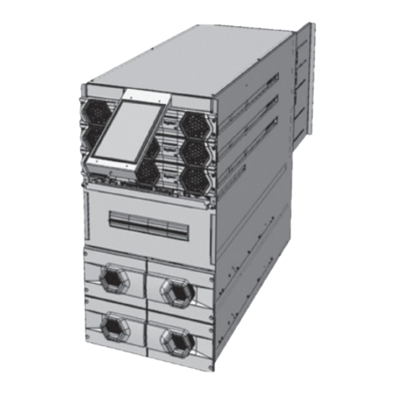
Page 34: Power Modules Installation
Once all the electrical connections have been made, close the distribution panel and fix it by screwing the torx M4x8 screws. It is then possible to move onto the insertion of the power modules into the UPS. Keor MOD RI 25 has one power module while Keor MOD 50 has two power modules. - Page 35 Keor MOD RI Remove the film protector from the front of the power module. Insert the power module in the free slot, making sure that its switch in the front is open. Make sure that the power module is abut and then close its front switch. Fix the module to the cabinet with the four...
-
Page 36: Battery Drawers Installation
4. Installation Battery drawers installation Keor MOD RI 25 may include two internal battery drawers while Keor MOD RI 50 may include four internal battery draw- ers. Each battery string is made up of two drawers There must be at least 1 KB (Battery Kit) every 25 kVA of nominal UPS power. For internal battery drawers and for external modular battery units, 1 KB is made up of 2 battery drawers. - Page 37 Keor MOD RI Connect the two provided cables on the free battery terminals that will connect the two battery packs with the other two that will be added in the next step. Insert the terminal covers and fix them to the packs with the adhesive tape.
- Page 38 4. Installation Connect in series the two new packs to the ones already in the drawer using the cable installed previously and respecting the polarity (connect a positive terminal to a negative terminal). Connect the free terminals of the two batteries located close to the handle of the drawer to the cables that are connected to the back of the drawer.
- Page 39 Keor MOD RI Fill the second drawer in the same way. After the two drawers are ready, push them inside the UPS cabinet till they are abut and fix them with four screws included in the accessory kit.
- Page 40 4. Installation CAUTION A drawer must be made up of batteries of the same brand and of the same manufacturing date.
-
Page 41: Sss Interface
Keor MOD RI SSS interface TERMINAL PINS FUNCTION CONFIGURABLE CONTACT 3 Maximum input voltage: 15V CONFIGURABLE CONTACT 4 15 kΩ pull-up CONFIGURABLE CONTACT 1 CONFIGURABLE CONTACT 2 Analogic EXTERNAL MAINTENANCE BYPASS floating SWITCH inputs EXTERNAL TEMPERATURE (maximum Input Voltage: 5V) It allows to check the temperature of the batteries for external cabinets. -
Page 42: Emergency Power Off (Epo)
4. Installation 4.5.1 Emergency Power Off (EPO) The UPS has a contact that can be used to activate the immediate stop of the equipment. It can be set as normally closed (NC) or normally open (NO) from the user interface. The default configuration is NC. The EPO terminal is found on pins 1 and 2 of contact N13 of the SSS interface. -
Page 43: Configuration And Start-Up
Keor MOD RI 5. Configuration and start-up DANGER All the configurations and start-up operations must be carried out exclusively by a SKILLED TECHNICIAN (para- graph 2.2.1). Pre-start-up checks Before powering the equipment, carry out the following checks: 1. Close all the distribution panels on the UPS cabinet. - Page 44 5. Configuration and start-up 4. Choose the desired language in the tab GENERAL by tapping on the pencil icon on the item Language.
- Page 45 Keor MOD RI 5. Set the desired voltage and frequency output in the tab SYSTEM by tapping on the pencil icon on the items Output Voltage and Output Frequency. In the same tab there is also the item Enable or disable walk-in function. If the UPS turns from battery mode to normal mode while it is connected to an external generator, especially with full load, there could be some frequency fluctuations causing a condition where the bypass is not available.
- Page 46 5. Configuration and start-up 6. If there is the additional PM for redundancy, tap on the SYSTEM tab. Then, tap on the Pencil icon of the item PM re- dundancy. The default value is 0. Select the value 1 if the additional PM for redundancy is installed.
- Page 47 Keor MOD RI 7. Select the tab BD to set the number of KB (Battery Kits) and the battery capacity in Ah of the single KB. Tap on the pencil icon of the item Number of Kit Batteries installed and insert the number of KB. Tap on the pencil icon of the item Capacity value of Kit Batteries [Ah] and insert the value of the battery capacity.
- Page 48 5. Configuration and start-up 8. In the BD tab, select the the charge mode of the UPS. There are 2 modes available: - Floating mode: the voltage on the batteries is maintained to 13.8 V. For this mode it is also possible to have a tune of the charging voltage according to the temperature detected by an internal sensor of the SSS (in case of internal battery drawers) or through an external sensor (in case of external battery cabinets).
- Page 49 Keor MOD RI 9. If there are two Keor MOD RI systems connected to an STS (see paragraph 4.2.11), it is necessary to set a proper con- figuration for one of the UPS in each system. Tap on the Settings icon of the menu bar at the bottom of the display. Select the System tab.
-
Page 50: Turning Off The Ups
5. Configuration and start-up Turning off the UPS Follow this procedure in case there is the need to turn off the UPS: 1. Tap on the General Commands icon of the menu bar at the bottom of the display. 2. Then locate the item System Power Off and tap on the button OFF to turn off the UPS. 3. -
Page 51: Maintenance
INSTALLATION and ORDINARY MAINTENANCE operations must be carried out only by SKILLED TECHNICIANS (paragraph 2.2.1). EXTRAORDINARY MAINTENANCE operations must be carried out only by LEGRAND TECHNICAL SUPPORT SERVICE. LEGRAND declines all liability for any injury or damage caused by activities carried out differently from the instructions written in this manual. Preventive maintenance The UPS does not contain parts for preventative maintenance by the operator. -
Page 52: Ordinary Maintenance
6. Maintenance Ordinary maintenance 6.3.1 Hot-swap procedure for the replacement of power modules The hot-swap procedure makes it possible to replace a faulty power module while the load is powered by the UPS in on-line mode. In case of a black-out during the procedure, there is no risk to power off the load since it is supplied by the other power modules. - Page 53 Keor MOD RI 6. Push the safety hook located on the top right of the PM to unlock the block and pull the PM to finalize the extraction. 7. Insert the new PM on the free slot making sure that the frontal switch is open and that the module is in abutment.
-
Page 54: Installation/Replacement Of Power Modules With The Ups In Maintenance Bypass Mode
6. Maintenance 6.3.2 Installation/replacement of power modules with the UPS in maintenance bypass mode If the hot-swap procedure explained in the previous paragraph is not applicable, it is possible to replace or even to add PM with the UPS in maintenance bypass mode. INDICATION During this procedure, the load is not protected by the UPS because it is powered from the bypass input line. - Page 55 Keor MOD RI 3. Tap on the General Commands icon of the menu bar at the bottom of the display. 4. Tap on the icon > of the item COMMANDS.
- Page 56 6. Maintenance 5. Tap on the Bypass on button of the item Force Bypass. The LEDs of the PM blink fast in orange. 6. Close the maintenance breaker by bringing it to the ON position. The load is powered directly from the bypass line. 7.
-
Page 57: Installation/Replacement Of Power Modules
Keor MOD RI 6.3.2.2 Installation/replacement of power modules Check that the procedure for setting the maintenance bypass mode described in paragraph 6.3.2.1 has been applied. To replace a PM: 1. Open the frontal switch of the PM to be replaced. - Page 58 6. Maintenance 4. Push the safety hook located on the top right of the PM to unlock the block and pull the PM to finalize the extraction. 5. Insert the new PM on the free slot making sure that the frontal switch is open and that the module is in abutment. 6.
-
Page 59: Exit The Ups From The Maintenance Bypass Mode
Keor MOD RI 6.3.2.3 Exit the UPS from the maintenance bypass mode 1. If present, close the battery disconnectors of the external battery cabinets and insert all the internal battery drawers. 2. Tap on the General Commands icon of the menu bar at the bottom of the display. Find the item System Power On and tap on the button ON to turn on the UPS. -
Page 60: Removal Of The Sss Drawer
6. Maintenance 6.3.3 Removal of the SSS drawer... -
Page 61: Battery Drawers Replacement
Keor MOD RI Battery drawers replacement WARNING A battery can present a risk of electrical shock and high short circuit current. Read and apply the safety instructions in chapter 2 before operating on batteries INDICATION The battery drawers must always be added/removed in multiples of two (1 KB consists of two battery drawers). Always replace just one KB at a time. -
Page 62: Installation/Replacement Of Battery Drawers With Ups In On-Line Mode
6. Maintenance 6.4.1 Installation/replacement of battery drawers with UPS in on-line mode To replace a battery drawer: 1. Check that the UPS has installed more than 1KB every 25kVA of power supplied to the output. 2. Check that the UPS is not working in battery mode and that the battery charger is in the “maintenance” or “standby” state. -
Page 63: Installation/Replacement Of Battery Drawers With Ups In Maintenance Manual Bypass
Keor MOD RI 6.4.2 Installation/replacement of battery drawers with UPS in maintenance manual bypass To replace a battery drawer: 1. Follow the procedure described in paragraph 6.3.2.1 for setting the UPS in maintenance bypass mode. 2. Extract the battery drawer until the safety block prevents to continue the extraction. -
Page 64: Replacing The Fuses And Surge Arrester (Din Rail)
It is mandatory to verify monthly the indication on the surge arrester. The device works correctly if the indicator is green. If the device is damaged, the indicator is red and the surge arrester must be replaced. Extraordinary maintenance Contact the LEGRAND Technical Support Service if there are failures that require the access to internal parts of the UPS. -
Page 65: Warehousing
- up to 2 months if the temperature is over +40°C (+104°F). CAUTION Batteries must never be stored if partially or totally discharged. LEGRAND is not liable for any damage or bad functioning caused to the UPS by wrong warehousing of the batteries. -
Page 66: Dismantling
8. Dismantling DANGER Dismantling and disposal operations must be carried out only by a SKILLED TECHNICIAN (paragraph 2.2.1). The instructions in this chapter are to be considered indicative: in every country there are different regulations regarding the disposal of electronic or hazardous waste such as batteries. It is necessary to strictly adhere to the standards in force in the country where the equipment is used. -
Page 67: Mechanical Characteristics
Keor MOD RI 9. Mechanical characteristics Keor MOD RI UPS are sold as empty power cabinets. It is necessary to purchase the power modules and the battery draw- ers separately. Cabinets (all the dimensions are in mm) TOUCH 256.7 PANEL 596.5... - Page 68 FRONTAL VIEW LEFT SIDE VIEW SLIDING PANEL BATTERY DRAWER 748.5 RIGHT SIDE VIEW FRONT VIEW LEFT SIDE VIEW BOTTOM ROOF COVER COVER BACK SIDE CABLE ENTRY BOTTOM VIEW TOP VIEW REAR VIEW 3 111 35 Keor MOD RI 50 kVA...
-
Page 69: Power Module Pm25
Keor MOD RI Power module PM25 (all the dimensions are in mm) -
Page 70: Battery Drawer
9. Mechanical characteristics Battery drawer (all the dimensions are in mm) -
Page 71: Technical Data
Keor MOD RI 10. Technical data Main features 3 111 34 3 111 35 Keor MOD RI 25 Keor MOD RI 50 Nominal Power (kVA) Active Power (kW) Number of power modules (1 free slot for redundancy) (1 free slot for redundancy) - Page 72 10. Technical data Output electrical characteristics (normal mode) 3 111 34 3 111 35 Keor MOD RI 25 Keor MOD RI 50 Rated output current (full load and 400V input voltage) Maximum output current (full load and 380V input voltage) Output voltage 380/400/415 ±...
- Page 73 Keor MOD RI Batteries and battery charger characteristics 3 111 34 3 111 35 Keor MOD RI 25 Keor MOD RI 50 Nominal battery voltage ± 264 (44 blocks) Battery voltage range ± 264 to ± 312 (44-52 blocks) Internal batteries...
- Page 74 10. Technical data Environmental conditions 3 111 34 3 111 35 Keor MOD RI 25 Keor MOD RI 50 Operating temperature 0 ÷ +40 (°C) Relative humidity 0% ÷ 95% non-condensing during operation Storage temperature -25 ÷ +55 (°C) (excluding batteries) Noise level at 1 metre 50 ÷...
-
Page 75: Tables
Keor MOD RI 11. Tables CAUTION The choice of the type and section of the power cables must be done according to the voltage and rated current as well as the local wiring standards and regulations. It is a responsibility of the installation engineer. - Page 76 10. Tables TABLE 3 Automatic breaker recommended for input and bypass line POWER AUTOMATIC CIRCUIT BREAKER 25 kVA In=50 A curve C Icp=10kA 50 kVA In=100 A curve C Icp=10kA TABLE 4 Residual current breaker recommended for input and bypass line POWER RESIDUAL CURRENT BREAKER (IΔn) 25 kVA...
- Page 77 Keor MOD RI...
- Page 78 Pro and Consumer Service BP 30076 - 87002 LIMOGES CEDEX FRANCE www.legrand.com Installer stamp Legrand reserves at any time the right to modify the contents of this booklet and to communicate, in any form and modality, the changes brought to the same.
Need help?
Do you have a question about the Keor MOD RI and is the answer not in the manual?
Questions and answers