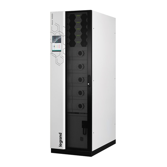
LEGRAND Keor MOD Additional Installation Instructions
Hide thumbs
Also See for Keor MOD:
- Installation manual (20 pages) ,
- Additional installation instructions (64 pages) ,
- Installation manual (52 pages)
Advertisement
Quick Links
Advertisement

Summary of Contents for LEGRAND Keor MOD
- Page 1 3 111 19 – 3 111 20 Keor MOD Additional installation instructions Part. LE13363AA-03/22-01 GF...
- Page 2 3 111 19 – 3 111 20 Keor MOD ENGLISH...
- Page 3 Keor MOD Index 1. Introduction 1.1 Content of the kit 2. Installation procedure 2.1 Step 1 2.2 Step 2 2.3 Step 3 2.4 Step 4 2.5 Step 5 2.6 Step 6 (only for 3 111 19)
- Page 4 1. Introduction This manual is an addendum to the installation manual for Keor MOD. It describes only the procedure to finalize the installation of the seismic basement of the Keor MOD with Seismic Kit 3 111 19 and 3 111 20.
- Page 5 Keor MOD 2. Installation procedure Step 1 Remove the UPS cabinet from the pallet by following the unpackaging instructions in the installation manual. Do not proceed with step 2 until the unpackaging has been completed. Step 2 Install the lateral mounts (A) to the ground keeping them aligned and with each other.
-
Page 6: Installation Procedure
2. Installation procedure Step 3 Align the unit with the guides anchored to the ground, refer to the image below to align the side holes, it is necessary to keep a distance of 16 mm. 16mm... - Page 7 Keor MOD Step 4 • Assemble the fins (a2) with the support feet using grub screws (a3), nuts (b3) M12 and flat washers. • Mount the assembly of the four fins on the front brackets using the respective M8X20 screws and washers.
- Page 8 2. Installation procedure Step 5 • Adjust the support feet one by one until the machine has reached the height of the fixing holes on the side shoulder (A). • Fix the side shoulders (A) with the preassembled shoulders (B) using the 12 (6 + 6) screws M10X20 (a4).
- Page 9 Step 6 (only for 3 111 19) Only for the 3 111 19 (Keor MOD 125 kVA), in addition to the seismic basement, there are also ten metal bars and twenty M4x8 screws to keep stable the battery packs in the drawers. For each battery drawer, after having followed...
- Page 10 2. Installation procedure The following picture shows the UPS with the seismic basement mounted:...
- Page 11 Keor MOD...


Need help?
Do you have a question about the Keor MOD and is the answer not in the manual?
Questions and answers