Table of Contents
Advertisement
Quick Links
Advertisement
Table of Contents

Related Manuals for Motorola N2U-OA200 Series


Summary of Contents for Motorola N2U-OA200 Series
- Page 1 Installation Manual N2U-OA200 Series EDFA...
- Page 2 CAUTION RISK OF ELECTRIC SHOCK CAUTION: TO REDUCE THE RISK OF ELECTRIC SHOCK, DO NOT REMOVE COVER (OR BACK). NO USER-SERVICEABLE PARTS INSIDE. REFER SERVICING TO QUALIFIED SERVICE PERSONNEL. Caution These servicing instructions are for use by qualified personnel only. To reduce the risk of electrical shock, do not perform any servicing other than that contained in the Installation and Troubleshooting Instructions unless you are qualified to do so.
- Page 3 Motorola, Inc. Motorola reserves the right to revise this publication and to make changes in content from time to time without obligation on the part of Motorola to provide notification of such revision or change. Motorola provides this guide without warranty of any kind, either implied or expressed, including, but not limited to, the implied warranties of merchantability and fitness for a particular purpose.
- Page 4 N2U-OA200 Series Installation Manual...
-
Page 5: Table Of Contents
Configuring for Telnet ............4-4 N2U-OA200 Series Installation Manual... - Page 6 ............. . C-19 N2U-OA200 Series Installation Manual...
- Page 7 Laser Radiation Warning ........... . E-6 Abbreviations and Acronyms Index N2U-OA200 Series Installation Manual...
- Page 8 Table 5-1: Front Panel LEDs and conditions......... . . 5-3 N2U-OA200 Series Installation Manual...
- Page 9 Figures Figure 1-1: N2U-OA200 Series EDFA ..........1-1 Figure 2-1: Front panel .
- Page 10 Contents-vi N2U-OA200 Series Installation Manual...
-
Page 11: Introduction
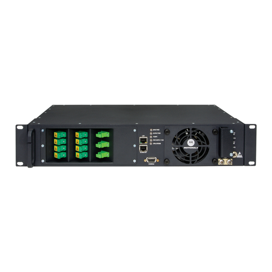
This manual describes how to install and operate the N2U-OA200*-*/SCA. The N2U-OA200 is a low-noise, C-band optical erbium-doped fiber amplifier (EDFA) for PON applications. The N2U-OA200 complements high-performance analog transmitters in topologies requiring amplification of 1550-nm optical signals. Figure 1-1: N2U-OA200 Series EDFA INPUT PWR OUTPUT PWR... -
Page 12: Document Conventions
Italic type Denotes a displayed variable, a variable that you must type, or is used for emphasis If You Need Help If you need assistance while working with the N2U-OA200 Series EDFA, contact the Motorola Technical Response Center (TRC): •... -
Page 13: Calling For Repairs
Introduction Calling for Repairs If repair is necessary, call the Motorola Repair Facility at 1-800-642-0442 for a Return for Service Authorization (RSA) number before sending the unit. The RSA number must be prominently displayed on all equipment cartons. The Repair Facility is open from 7:00 AM to 4:00 PM Pacific Time, Monday through Friday. - Page 14 Introduction N2U-OA200 Series Installation Manual...
-
Page 15: Overview
The N2U-OA200 supports SNMP and has a console port to facilitate setup and monitoring. With a customer-supplied network monitor and the provided MIB file, all monitorable and settable parameters are available remotely. Applications The N2U-OA200 supports the following applications: • • Analog transport with high distribution N2U-OA200 Series Installation Manual... -
Page 16: Front Panel
INPUT POWER Yellow: A minor alarm has been detected. There is a Loss of Signal (LOS) or the input is above the high alarm limit. Off: If the LED is off, verify that system power is available. N2U-OA200 Series Installation Manual... - Page 17 The fan or the DC power supply has failed or the DC power supply is in over-current. Off: If the LED is off, verify that system power is available. This connector provides tapped-screw mounting holes for attaching a frame GROUND ground lug and wiring. ATTACHMENT N2U-OA200 Series Installation Manual...
- Page 18 Overview N2U-OA200 Series Installation Manual...
-
Page 19: Installation
— Listed two-hole copper grounding lug (0.25 in. [0.635 cm] diameter bolt hole size, 0.625 in. [1.5875 cm] center-to-center hole spacing) • Ensure that your equipment configuration meets the minimum requirements for the installation you will perform. Caution! Only trained and qualified personnel should install, replace, or service this equipment. N2U-OA200 Series Installation Manual... -
Page 20: Creating A Site Log
___________ _____________________ ___________ Accessories received _____________________ ___________ Required tools available _____________________ ___________ Additional equipment available Site power voltages verified _____________________ ___________ Initial electrical connections established _____________________ ___________ N2U-OA200 fully installed _____________________ ___________ _____________________ ___________ Operation verified N2U-OA200 Series Installation Manual... -
Page 21: Rack-Mounting The Chassis
Figure 3-1: Rack-Mounting the N2U-OA200 Caution! Use only the hardware provided with the N2U-OA200. Failure to use the provided hardware may result in unintended damage. If the hardware is lost, contact Motorola as described in “If You Need Help” on page 1-2. -
Page 22: Optical Connection
Install a power conditioner, if necessary, to ensure proper voltages and power levels in the source voltage. Caution! Use only the hardware provided with the N2U-OA200. Failure to use the provided hardware may result in unintended damage. If hardware is lost, contact Motorola for a replacement. N2U-OA200 Series Installation Manual... - Page 23 The protective cover for the DC power terminals should be installed at all times when the equipment is energized, except for any necessary maintenance or troubleshooting. Warning! When installing or replacing the unit, the ground connection must always be made first and disconnected last. N2U-OA200 Series Installation Manual...
-
Page 24: Dc Power Connection
Remove the two screws provided for securing the ground lug to the N2U-OA200. Connect the 8 AWG grounding wire to the grounding lug. The other end of the wire should be suitably grounded. Install the grounding lug on the N2U-OA200, using the two provided screws and washers. N2U-OA200 Series Installation Manual... -
Page 25: Connecting The Dc Power
Alarm contacts (through RJ-45 connector) • Console port (through RS-232) “Connector Pinouts” on page B-1 for the RJ-45 and RS-232 connector wiring layouts. “Configuring Local Serial Communication” on page 4-1 for information about the RS-232 console port. N2U-OA200 Series Installation Manual... -
Page 26: Setting Up Alarm Contacts
— Displays the N2U-OA200 input, alarm limits, hysteresis, and alarm state. • getoutdata — Displays the N2U-OA200 output power and gain, alarm limits, hysteresis, and alarm state. • getpumpdata — Displays the N2U-OA200 pump data, alarm limits, hysteresis, and alarm state. N2U-OA200 Series Installation Manual... -
Page 27: Configuration
Launch a serial port communication utility such as Hyperterminal on the PC or laptop and configure it to communicate at 38400 baud, no parity, 8 bit data, 1 stop bit, and no flow control. Press to display the login prompt. The N2U-OA200 is now ready for basic system configuration. ENTER N2U-OA200 Series Installation Manual... -
Page 28: Configuring A Basic System
The Element Management System and the CLI enable you to view the following information about the firmware programs stored in the N2U-OA200: • Firmware revision level in each bank • Firmware code CRC in each bank • Which bank of firmware will run at the next boot up N2U-OA200 Series Installation Manual... -
Page 29: Monitoring Alarms And Traps
To configure the software on the N2U-OA200 for console port-based monitoring: Type traps on to display the N2U-OA200 traps on the CLI. Type alarms to display the N2U-OA200 alarms. Type status to check the optical and environmental status of the N2U-OA200. N2U-OA200 Series Installation Manual... -
Page 30: Configuring Remote Communication
The default alarm contact state is normally open. Depending on which fault condition occurs, specific alarm contacts are closed. The corresponding N2U-OA200 LEDs turn on or off, as described in “Front Panel” on page 2-2. Pinout Alarm Alarm 1+ (major) Alarm 1- Alarm 2+ (minor) Alarm 2- N2U-OA200 Series Installation Manual... -
Page 31: Troubleshooting
This section describes basic fault investigation and diagnostic (troubleshooting) procedures for the N2U-OA200: If the problem exists after you review the N2U-OA200 status and attempt to reprovision the amplifier, contact the Motorola TRC as described in “If You Need Help” on page 1-2 or: •... -
Page 32: Verifying The Alarm Connection
Front panel indicators — Includes the LEDs on the front panel, which help to identify a failure. • Connecting cables — Includes all of the interface cables that connect the equipment to any transmission circuit or external device. N2U-OA200 Series Installation Manual... -
Page 33: Reading The Front Panel Leds
DC power supply is in over-current. • Check to see that external power is available and that the wiring is properly and firmly connected to the appropriate screw terminals. • Check to see that the fan is operational. N2U-OA200 Series Installation Manual... - Page 34 (Input) connector, at the transmitting (Output) optical fiber connector, or the monitoring (Optical Monitor) connector. When an optical cable is not attached, place the supplied protective cap over the connector and the optical fiber cable. N2U-OA200 Series Installation Manual...
-
Page 35: Specifications
50 Watts maximum for 600 mW EDFA 30 Watts maximum for 300 mW EDFA 25 Watts maximum for 200 mW EDFA 20 Watts maximum for 100 mW EDFA 0 to +55 Operating Temperature Storage Temperature to + 70 N2U-OA200 Series Installation Manual... -
Page 36: Communications
21 CFR 1040 FCC Part 15 (CFR 47) Class A ICES-003 Class A EN 55022 Class A CISPR22 Class A AS/NZS 3548 Class A VCCI Class A EN 55024 ETS 300 386 EN 50082-1 EN 61000-3-2 EN 61000-3-3 N2U-OA200 Series Installation Manual... -
Page 37: Nebs And Etsi Specifications (Applies To Dc-Powered Units
NEBS and ETSI Specifications (Applies to DC-powered units) GR-63 Core NEBS Level 3 Requirements GR-1089-Core NEBS Level 3 Requirements ETS 300 019 Storage Class 1.1 ETS 300 019 Transportation Class 2.3 ETS 300 019 Stationary Use Class 3.1 N2U-OA200 Series Installation Manual... - Page 38 Specifications N2U-OA200 Series Installation Manual...
-
Page 39: Connector Pinouts
Pair 1 (pins 1 and 2): Shorted if a major alarm exists Pair 2 (pins 3 and 4): Shorted if a minor alarm exists Pair 3 (pins 5 and 6): Uncommitted (always open) Pair 4 (pins 7 and 8): Uncommitted (always open) N2U-OA200 Series Installation Manual... - Page 40 Connector Pinouts N2U-OA200 Series Installation Manual...
-
Page 41: Command Reference
This appendix alphabetically lists and describes the N2U-OA200 commands. All commands are case insensitive. To display a list of available commands, type help. To display the syntax for a command, type help [command]. All commands are protected by the master password (see setpassword). N2U-OA200 Series Installation Manual... -
Page 42: Alarms
This command has no arguments or keywords. Types Does not change configuration. Modes Master password protected. History Rev A: This command was introduced. Example The following example shows how to display the alarms. $ alarms Optical Input Power Minor Alarm N2U-OA200 Series Installation Manual... -
Page 43: Date
Modes Master password protected. History Rev A: This command was introduced. Example The following example shows how to change the date. $ date 2003-10-01 The following example shows how to get the date. $ date 2003-October-1 N2U-OA200 Series Installation Manual... -
Page 44: Devinfo
Date Code : 01012003 Part Number : 496903-001 Man Location : NO Num Inputs Num Outputs : 16 Num Pumps Clei Code : 1122AA34 Related Commands setname Changes the unit name. getname Displays the unit name. N2U-OA200 Series Installation Manual... - Page 45 The following example shows how to change the download auto reset state. $ dl start Related Commands setdlfile Changes the download file name. Displays the download auto reset state. getdlautorst setdlautorst Changes the download auto reset state. dlstat Displays the download status. N2U-OA200 Series Installation Manual...
-
Page 46: Dlstat
Programming firmware bank Verify programmed firmware bank Verify auto reset state Download halted Related Commands Changes the download file name. setdlfile getdlfile Displays the download file name. setdlautorst Changes the download auto reset state. Starts/Stops the download process. N2U-OA200 Series Installation Manual... -
Page 47: Fwinfo
: Programmed Bank 1 state : Not Programmed Active bank : Bank 0 Bank 0 status : Pass Bank 1 status : Pass Bank 0 CRC : 5ADE Bank 1 CRC Bank 0 REV Bank 1 REV N2U-OA200 Series Installation Manual... -
Page 48: Getcomstr
Modes Master password protected. History Rev A: This command was introduced. Example The following example shows how to display the unit name. $ getcomstr operator Community String Operator: private Related Commands setcomstr Changes the community string. N2U-OA200 Series Installation Manual... -
Page 49: Getdlautorst
$ getdlautorst Download Auto Reset: on Related Commands Changes the download file name. setdlfile getdlfile Displays the download file name. setdlautorst Changes the download auto reset state. Starts/Stops the download process. dlstat Starts/Stops the download process. N2U-OA200 Series Installation Manual... -
Page 50: Getdlfile
$ getdlfile Download File name: oa200_A.gx2 Related Commands Changes the download file name. setdlfile getdlautorst Displays the download auto reset state. setdlautorst Changes the download auto reset state. Starts/Stops the download process. Starts/Stops the download process. dlstat N2U-OA200 Series Installation Manual... -
Page 51: Getgateipadd
Master password protected. History Rev A: This command was introduced. Example The following example shows how to display the Gateway IP address. $ getgateipadd Gateway IP Address: 168.084.213.129 Related Command Changes the Gateway IP address. setgateipadd N2U-OA200 Series Installation Manual... -
Page 52: Getindata
The following example shows how to display the data. $ getindata Input (dBm) Low Limit High Limit Hysteresis Alarm State ----------- --------- --------- --------- --------- 10.00 6.00 12.00 No Alarm Related Command N2U-OA200 setinlim Changes the input alarm limits. N2U-OA200 Series Installation Manual... -
Page 53: Getipadd
Does not change configuration. Modes Master password protected. History Rev A: This command was introduced. Example The following example shows how to display the data. $ getipadd Network IP Address: 168.084.213.132 Related Commands Changes the Network IP address. setipadd N2U-OA200 Series Installation Manual... -
Page 54: Getipmask
Master password protected. History Rev A: This command was introduced. Example The following example shows how to display the Network IP Mask. $ getipadd Network IP Mask: 255.255.000.000 Related Command Changes the Network IP mask. setipmask N2U-OA200 Series Installation Manual... -
Page 55: Getlowpwrmode
Modes Master password protected. History Rev A: This command was introduced. Example The following example shows how to display the power mode. $ getlowpwrmode Low Power Mode: off Related Command Changes the low power mode. setlowpwrmode N2U-OA200 Series Installation Manual... -
Page 56: Getmacadd
This command has no arguments or keywords. Types Does not change configuration. Modes Master password protected. History Rev A: This command was introduced. Example The following example shows how to display the Network MAC address. $ getmacadd Network MAC Address: 1A1518171918 N2U-OA200 Series Installation Manual... -
Page 57: Getname
Rev A: This command was introduced. Example The following example shows how to display the unit name. $ getname Unit Name: OA200 Related Commands Changes the unit name. setname N2U-OA200 devinfo Displays all device information on the including unit name. N2U-OA200 Series Installation Manual... -
Page 58: Getoutdata
Output # Output Low Limit High Limit Hysteresis Alarm State ----------- --------- --------- --------- --------- --------- 8 gain (dB) 1.00 8 pwr (dBm) 10.00 6.00 12.00 No Alarm Related Commands N2U-OA200 Changes the output alarm limits. setoutlim N2U-OA200 Series Installation Manual... -
Page 59: Getpumpdata
--------- --------- --------- --------- --------- 1 lsr temp (C) 23.00 22.00 24.00 No Alarm 1 bias curr (mA) 10.00 12.00 No Alarm 1 tec curr (mA) 10.00 1 opt pwr (mW) 10.00 6.00 12.00 No Alarm N2U-OA200 Series Installation Manual... -
Page 60: Gettempdata
The following example shows how to display temperature data. $ gettempdata Mod Temp Low Limit High Limit Hysteresis Alarm State ----------- --------- --------- --------- --------- 25.00 -25.00 75.00 2.00 No Alarm Related Commands N2U-OA200 settemplim Changes the temperature alarm limits. N2U-OA200 Series Installation Manual... -
Page 61: Gettrapdest
The following example shows how to display the trap destination address. $ gettrapdest all Dest # Trap Address ------- --------------- 168.084.213.134 000.000.000.000 000.000.000.000 000.000.000.000 000.000.000.000 000.000.000.000 000.000.000.000 000.000.000.000 000.000.000.000 000.000.000.000 Related Command settrapdest Changes the Trap destination address. N2U-OA200 Series Installation Manual... -
Page 62: Reset
This command resets the N2U-OA200. To display the alarms, use the reset command. Syntax This command has no arguments. Types Does not change configuration. Modes Master password protected. History Rev A: This command was introduced. Examples The following example shows how to reset the N2U-OA200. $ reset N2U-OA200 Series Installation Manual... -
Page 63: Rstalarmlims
Syntax This command has no arguments. Types Changes configuration. Modes Master password protected. History Rev A: This command was introduced. Examples The following example shows how to reset the alarm limits on the N2U-OA200. $ rstalarmlims N2U-OA200 Series Installation Manual... -
Page 64: Rstalarms
This command resets the N2U-OA200. To display the alarms, use the rstalarms command. Syntax This command has no arguments. Types Does not change configuration. Modes Master password protected. History Rev A: This command was introduced. Examples The following example shows how to reset the alarms N2U-OA200. $ rstalarms N2U-OA200 Series Installation Manual... -
Page 65: Setcomstr
Types Changes configuration. Modes Master password protected. History Rev A: This command was introduced. Example The following example shows how to change the unit name. $ setcomstt operator edfa Related Command Displays the community string. getcomstr N2U-OA200 Series Installation Manual... -
Page 66: Setdlautorst
The following example shows how to change the download auto reset state. $ setdlautorst off Related Commands getdlfile Displays the download file name. Changes the download file name. setdlfile getdlautorst Displays the download auto reset state. Starts/Stops the download process. Displays the download status. dlstat N2U-OA200 Series Installation Manual... -
Page 67: Setdlfile
The following example shows how to change the download file name. $ setdlfile oa200_A.gx2 Related Commands getdlfile Displays the download file name. Displays the download auto reset state. getdlautorst Changes the download auto reset state. setdlautorst Starts/Stops the download process. dlstat Displays the download status. N2U-OA200 Series Installation Manual... -
Page 68: Setgateipadd
Changes configuration. Modes Master password protected. History Rev A: This command was introduced. Examples The following example shows how to change the Gateway IP address. $ setgateipadd 168.084.213.130 Related Commands getgateipadd Displays the Gateway IP address. N2U-OA200 Series Installation Manual... -
Page 69: Setinlim
Rev A: This command was introduced. Examples The following example shows how to change the input low alarm limit. $ setinlim low 4.0 Related Commands N2U-OA200 Displays the input, alarm limits, hysteresis and alarm state. getindata N2U-OA200 Series Installation Manual... -
Page 70: Setipadd
Changes configuration. Modes Master password protected. History Rev A: This command was introduced. Examples The following example shows how to change the Network IP address. $ setipadd 168.084.213.133 Related Commands getipadd Displays the network IP address. N2U-OA200 Series Installation Manual... -
Page 71: Setipmask
Changes configuration. Modes Master password protected. History Rev A: This command was introduced. Examples The following example shows how to change the Network IP mask. $ setipmask 255.255.255.000 Related Command network IP mask getipmask Displays the N2U-OA200 Series Installation Manual... -
Page 72: Setlowpwrmode
Changes configuration. Modes Master password protected. History Rev A: This command was introduced. Examples The following example shows how to change the low power mode. $ setlowpwrmode on Related Commands N2U-OA200 getlowpwrmode Displays the low power mode. N2U-OA200 Series Installation Manual... -
Page 73: Setname
The following example shows how to change the unit name. $ setname OA200-1 “ ” $ setname OA200 1 Related Command getname Displays the unit name. N2U-OA200 devinfo Displays all device information on the including unit name. N2U-OA200 Series Installation Manual... -
Page 74: Setoutlim
Rev A: This command was introduced. Examples The following example shows how to change the output power low alarm limit. $ setoutlim 1 low 4.0 Related Command N2U-OA200 getoutdata Displays the output gain and power, alarm limits, hysteresis and alarm state. N2U-OA200 Series Installation Manual... -
Page 75: Setpassword
Enter the current password. newpasswd Enter new password. Types Changes configuration. Modes Master password protected. History Rev A: This command was introduced. Examples The following example shows how to change the download auto reset state. $ setpassword oa200 myoa200 N2U-OA200 Series Installation Manual... -
Page 76: Settemplim
Rev A: This command was introduced. Examples The following example shows how to change the temperature high alarm limit. $ settemplim high 70.0 Related Command N2U-OA200 Displays the temperature, alarm limits, hysteresis and alarm state. gettempdata N2U-OA200 Series Installation Manual... -
Page 77: Settrapdest
Changes configuration. Modes Master password protected. History Rev A: This command was introduced. Examples The following example shows how to change the Trap destination address. $ settrapdest 2 168.084.213.134 Related Command Displays the trap destination address. gettrapdest N2U-OA200 Series Installation Manual... -
Page 78: Status
Severity OK EEPROM Severity OK CAL Data Severity OK Flash Severity OK Boot Severity OK Alarm Limit Severity OK Power Supply Severity OK Severity OK Overcurrent Severity OK Thermal Severity OK Shutdown Reduce Power Severity OK N2U-OA200 Series Installation Manual... -
Page 79: Switchbk
Syntax This command has no arguments. Types Does not change configuration. Modes Master password protected. History Rev A: This command was introduced. Examples The following example shows how to display the status. $ switchbk N2U-OA200 Series Installation Manual... -
Page 80: Time
Modes Master password protected. History Rev A: This command was introduced. Examples The following example shows how to change the time. $ time 08:12:00 The following example shows how to get the time. $ time 8:12:00.16 N2U-OA200 Series Installation Manual... - Page 81 Reduce Power Major Alarm Reduce Power No Alarm FLASH Error Minor Alarm FLASH Error No Alarm Boot Error Minor Alarm Boot Error No Alarm Alarm Data CRC Minor Alarm Alarm Data CRC No Alarm Call Data CRC Minor Alarm N2U-OA200 Series Installation Manual...
- Page 82 Factory Data CRC Error Minor Alarm Factory Data CRC Error No Alarm Re-initializing EEPROM Bad Download File Download File Not Found Download Complete Download Failed Download Started Server Not Found Alarm Transfer Complete Transfer EFS Error Server Error Transfer Timeout N2U-OA200 Series Installation Manual...
-
Page 83: Translated Safety Warnings
This appendix contains the translations of the following safety warnings: • Wrist Strap Warning (see page E-2) • Restricted Area Warning (see page E-3) • Qualified Personnel Warning (see page E-4) • DC Protection Warning (see page E-5) • Laser Radiation Warning (see page E-6) N2U-OA200 Series Installation Manual... -
Page 84: Wrist Strap Warning
Använd jordade armbandsremmar under denna procedur för att förhindra elektrostatisk skada på Varning! kortet. Rör inte vid baksidan med handen eller metallverktyg då detta kan orsaka elektrisk stöt. N2U-OA200 Series Installation Manual... -
Page 85: Restricted Area Warning
Denna enhet är avsedd för installation i områden med begränsat tillträde. Ett område med begränsat tillträde får endast tillträdas av servicepersonal med ett speciellt verktyg, lås och nyckel, eller annan säkerhetsanordning, och kontrolleras av den auktoritet som ansvarar för området. N2U-OA200 Series Installation Manual... -
Page 86: Qualified Personnel Warning
Este equipamento deverá ser instalado ou substituído apenas por pessoal devidamente treinado e qualificado. ¡Atención! Estos equipos deben ser instalados y reemplazados exclusivamente por personal técnico adecuadamente preparado y capacitado. Denna utrustning ska endast installeras och bytas ut av utbildad och kvalificerad personal. Varning N2U-OA200 Series Installation Manual... -
Page 87: Dc Protection Warning
Varning! Denna produkt förlitar sig på byggnadens installation för skydd mot kortslutning (överström). Se till att en registrerad och certifierad säkring eller ett överspänningsskydd på 25 A, minst 60 V likström, används på alla strömförande ledare. N2U-OA200 Series Installation Manual... -
Page 88: Laser Radiation Warning
Es posible que las fibras desconectadas emitan radiación láser invisible. No fije la vista en los ¡Advertencia! rayos ni examine éstos con instrumentos ópticos. Osynlig laserstrålning kan avges från frånkopplade fibrer eller kontaktdon. Rikta inte blicken in i Varning! strålar och titta aldrig direkt på dem med hjälp av optiska instrument. N2U-OA200 Series Installation Manual... -
Page 89: Abbreviations And Acronyms
CLEI Common Language Equipment Identifier command line interface EDFA erbium-doped fiber amplifier File Transfer Protocol Internet Protocol media access control network element polarization mode dispersion Trivial File Transfer Protocol TFTP N2U-OA200 Series Installation Manual... - Page 90 Abbreviations and Acronyms N2U-OA200 Series Installation Manual...
-
Page 91: Index
Conventions see Document conventions DC input power connecting 3-6–3-7 grounding the chassis 3-6 troubleshooting 5-1, 5-2 Document conventions 1-2 Ethernet connection troubleshooting 5-1, 5-2 front panel features (table) 2-2 figure 2-2 grounding the chassis 3-6 Help 1-2 Installation 3-1 N2U-OA200 Series Installation Manual... - Page 92 3-2 Support 1-2 Technical Response Center (TRC) contact 1-2 Technical Support 1-2 Telnet configuring 4-4 Troubleshooting 5-1 troubleshooting alarm connections 5-2 basic diagnostic procedures 5-1 DC input power 5-1, 5-2 Ethernet connection 5-1, 5-2 LEDs 5-3 N2U-OA200 Series Installation Manual...
- Page 93 N2U-OA200 Series Installation Manual...
- Page 94 Visit our website at: www.motorola.com 474765-001 1/04 MGBI...
Need help?
Do you have a question about the N2U-OA200 Series and is the answer not in the manual?
Questions and answers