
Related Manuals for Digitimer SPP-100


Summary of Contents for Digitimer SPP-100
- Page 1 Digitimer SPP-100 Extracellular Amplifier/Filter OPERATOR’S MANUAL For Research Use Only “ Digitimer” is a registered trademark of Digitimer Limited...
- Page 2 Product Registration Please take time out to register your new product. You can even do it online at:- www.digitimer.com/register...
-
Page 3: Table Of Contents
Unpacking ..........................6 Supplied Accessories ........................6 Optional Accessories ........................6 EU Declaration of Conformity ....................7 Introduction to the SPP-100 ...................... 8 Hardware Overview ........................9 Pre-amplifier Headstage ......................9 Main Amplifier/Filter Unit ...................... 9 Amplifier Controls ........................10 Powering On and Off ...................... - Page 4 Digitimer Limited SPP-100 Operator’s Manual Issue 1 Amplifier Input & Signal Output Connections ................. 14 Headstage Electrode Connections ................... 14 Metal Micro-electrodes ......................14 Fluid Filled Pipette Electrodes ....................15 Making Differential Recordings .................... 15 Symbols & Display Icons ......................16 Specifications ...........................
-
Page 5: Contact Addresses
Website: www.digitimer.com Major Representative North America: Digitimer North America, LLC One East Broward Blvd. Suite 700 Fort Lauderdale FL 33301 Telephone: +1 954 334-1070 Fax: +1 954 206-6227 E-mail: svalenti@digitimer.com Please contact Digitimer for information regarding representation in other countries. -
Page 6: Product Registration
This web address is your point of contact for all questions regarding the SPP-100. The contents of this site are now growing rapidly, so please bookmark it so that you can visit it regularly to check out the new items. -
Page 7: Precautions And Warnings
Explosion and Fire The SPP-100 must not be used in an explosive atmosphere or volatile atmosphere. Damage The SPP-100 and/or any accessories must not be used if there are any signs of external damage. Moisture The SPP-100 and/or any accessories must not be used if any parts are wet or damp. -
Page 8: Unpacking
SPP-100 Operator’s Manual Issue 1 Unpacking After unpacking the SPP-100 from the shipping carton, please inspect it and accessories for any sign of shipping damage. Please contact the carrier and your supplier, or Digitimer Limited, immediately if there is any damage. Do not dispose of the shipping carton. The carrier will want to examine the shipping carton to process a damage claim. -
Page 9: Eu Declaration Of Conformity
Digitimer Limited SPP-100 Operator’s Manual Issue 1 EU Declaration of Conformity Not yet available... -
Page 10: Introduction To The Spp-100
50/60Hz notch filters. Because the SPP-100 is a standalone instrument and uses an external AC/DC power supply, it provides a cost-effective alternative to the modular NeuroLog system and will be equally at home within research or teaching laboratories. -
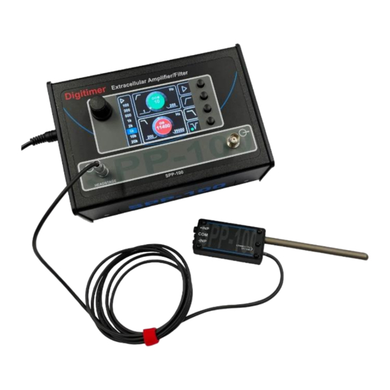
Page 11: Hardware Overview
100-HS). Main Amplifier/Filter Unit The SPP-100 main amplifier/filter unit incorporates an external power supply input socket, a 4-pole headstage connection socket and a BNC connector for the amplified signal output. A mini USB connector is available for possible future use, but does not currently serve any... -
Page 12: Amplifier Controls
The main amplifier unit includes two fold-out feet that offer an alternative viewing angle. Amplifier Controls The SPP-100 is easy to use and has very few controls. A single rotary encoder with push- button action, located to the left of the display screen, is used to adjust settings and to power the unit on and off. -
Page 13: Powering On And Off
4-pole Lemo connector, ensuring the key-way marked with the red dot is correctly aligned. 2. Connect the supplied SPP-100 external power supply to the power input socket on the left side of the SPP-100 Amplifier/Filter and ensure the mains supply is switched 3. -
Page 14: Amplifier Gain
SPP-100 is not in use. Note that the display brightness, filter and gain settings persist when the unit is powered off and on, but the SPP-100 always starts up with the rotary encoder in Gain control mode. Amplifier Gain A single press of the upper of the four buttons selects the Gain control. -
Page 15: 50/60Hz Notch Filter
Setting the Notch Filter to 50Hz or 60Hz By default, the SPP-100 Notch Filter is factory set to 50Hz. For regions where the mains electricity supply operates at 60Hz, it will be necessary to adjust the Notch Filter value. -
Page 16: Amplifier Input & Signal Output Connections
SPP-100 Operator’s Manual Issue 1 Amplifier Input & Signal Output Connections The SPP-100 utilises a dedicated SPP-100-HS Preamplifier Headstage and this must be connected via the 4-pole Lemo socket on the left-hand side of the front panel. When inserting, ensure the key-way marked with the red dot is aligned correctly. -
Page 17: Fluid Filled Pipette Electrodes
-INP and COM inputs and the flying lead is used to provide the ONLY ground connection for the preparation. In this way any common-mode interference picked up at both the +INP and -INP inputs of the headstage can be summed out by the SPP-100 main unit. -
Page 18: Symbols & Display Icons
Digitimer Limited SPP-100 Operator’s Manual Issue 1 Symbols & Display Icons The table below shows the symbols used on the SPP-100 main unit and headstage. Amplifier Gain Low Cut Filter High Cut Filter Notch Filter Off Headstage Input Socket Notch Filter On Headstage signal input. -
Page 19: Specifications
Power Supply Input: 24V DC, 1A (Universal AC/DC with IEC 60320 C14 receptacle) Connections Headstage Input: 4-way 0B Series Lemo Output: BNC plug USB: mini USB (Not currently used) Power: 2.1mm DC Barrel Connector (Only use AC/DC adapter supplied by Digitimer) -
Page 20: Signal Path
Digitimer Limited SPP-100 Operator’s Manual Issue 1 Signal Path Signal Path: AC (0.05Hz minimum Low-Cut/High-Pass) Overall Gain: x100, x200, x500, x1000, x2000, x5000, x10000, x20000; ±5% Low-Cut (High-Pass): 3 Ranges; -3dB second order; ±5% 0.05Hz – 2.50 Hz (0.01Hz increments) 2.50Hz –... -
Page 21: Warranty Information
Warranty Information Limited Warranty Digitimer Limited warrants to the first purchaser, for a period of one year from the date of purchase, that this Digitimer instrument (hereafter referred to as the “Product”) will be free from defective workmanship and materials, and agrees that it will, at its option, either repair the defect or replace the defective Product or part thereof at no charge to the purchaser for parts and labour. -
Page 22: References
SPP-100 Operator’s Manual Issue 1 References The SPP-100 is a new product so at this time there are not peer reviewed publications that cite its use. If you publish research that uses the Digitimer SPP-100, the correct citation format should SPP-100 Extracellular Amplifier/Filter (Digitimer Limited, Welwyn Garden City, UK) We appreciate receiving PDF copies of any publications that employ our products. - Page 23 Digitimer Limited SPP-100 Operator’s Manual Issue 1...
- Page 24 Digitimer Limited SPP-100 Operator’s Manual Issue 1 Digitimer Limited 37 Hydeway Welwyn Garden City AL7 3BE Web: www.digitimer.com Email: sales@digitimer.com Issue 1 – Last updated 9/1/24 N:\Docs\Company\Manuals\SPP-100 Extracellular Amplifier\SPP-100 Manual Issue 1.docx...
Need help?
Do you have a question about the SPP-100 and is the answer not in the manual?
Questions and answers