
Related Manuals for Digitimer DS8R


Summary of Contents for Digitimer DS8R
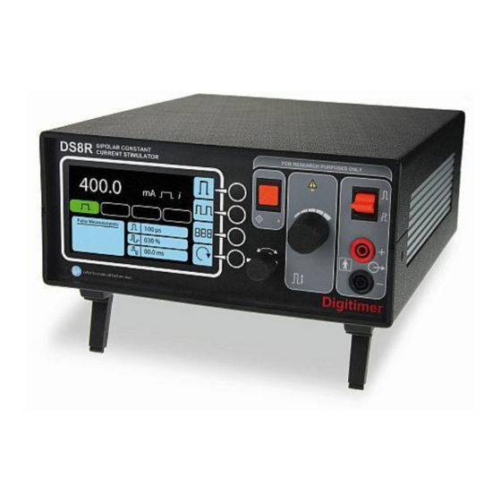
- Page 1 Digitimer DS8R BIPOLAR CONSTANT CURRENT STIMULATOR OPERATOR’S MANUAL Applicable to DS8R with Mod. State 1 or higher For Research Use Only “ Digitimer” is a registered trademark of Digitimer Limited...
- Page 2 Digitimer Ltd - DS8R Operator’s Manual Version 2.0 Blank Page Digitimer Ltd. Copyright ©2019...
-
Page 3: Table Of Contents
Digitimer Ltd - DS8R Operator’s Manual Version 2.0 Table of Contents Section 1 - General Information......................6 DS8R Intended Usage & Description ....................6 Precautions and Warnings ......................7 Operator’s Manual ........................7 Indications for Use ........................7 Risks to Subject Safety........................ 7 Subject Exclusion Criteria ...................... - Page 4 Digitimer Ltd - DS8R Operator’s Manual Version 2.0 Front Panel Components ......................13 Front Panel Printed Symbols ....................15 Rear Panel Components ......................15 Rear Panel Symbols ........................16 Audible Alerts & Warnings ....................... 17 Initial Hardware Check ......................... 17 Section 3 - Configuration &...
- Page 5 Software Installation ........................29 Running the Software ........................31 Tour of the Software ........................31 Muting the Out of Compliance (OOC) Beep ................32 Triggering the DS8R from the software..................32 Firmware Update ......................... 32 DS8R API Programmer’s References ..................... 34 Digitimer Ltd.
-
Page 6: Section 1 - General Information
The DS8R is fully capable as a standalone stimulator, but control is also possible using the supplied Windows PC control software via a USB interface. The PC software provides the operator with the ability to trigger the stimulator and change stimulation parameters and other settings. -
Page 7: Precautions And Warnings
The DS8R is not a medical device, does not have any medical device certification and is not suitable for treatment or diagnostic use. However, it has been designed for safe use in human research applications and meets all of the following standards. -
Page 8: Subject Exclusion Criteria
It is important, therefore, that the output terminals of the DS8R stimulator are only connected to the stimulating electrodes and to nothing else. Attempts to measure the stimulus current, by inserting a resistor into one stimulating lead and using an oscilloscope to measure the voltage drop across the resistor, are likely to violate the rule of not connecting a path to earth/ground to either side of the stimulator output. -
Page 9: Explosion And Fire
Please contact us for a reference number and instructions before despatching the unit. As no parts of the DS8R are expected to age the only limitation to the service life is likely to be the ongoing ability to replace electronic components that may randomly fail. The components chosen are used conservatively and are all well-established parts so availability can be expected for many years. -
Page 10: Supplied Accessories
Windows compatible virtual front panel software (supplied on USB Stick). Please note that the USB cable supplied is specifically for use with the DS8R. USB cables from other suppliers are NOT suitable for use with this stimulator and may result in increased EMC emissions or decreased EMC immunity. -
Page 11: Specifications
Limit is set at 50mA, the input voltage input is re-scaled so that 0 to +10V gives 0 to 50mA. Lag: 1ms (i.e. the DS8R will respond to amplitude changes at a maximum frequency of 1kHz) Accuracy: ±1mA Digitimer Ltd. -
Page 12: Indicators
Digitimer Ltd - DS8R Operator’s Manual Version 2.0 Indicators TRIGGER LED - Amber, flashes for each trigger received FAULT/ERROR LED – Steady Amber, indicating internal hardware fault. Flashing Amber, indicating firmware update in progress. LCD Display Showing: Set Current, Set Pulse Duration, Set Recovery Phase Ratio, Set Interphase Interval Pulse Mode, Polarity Mode, Amplitude Control Mode Pulse Measurements (Accuracy ±(5% +2)) -
Page 13: Section 2 - Hardware Overview
This momentary action toggle switch is used to enable, disable or reset the DS8R. Upward deflection enables the output and downward deflection disables a previously enabled output. Downward deflection can also be used to reset the DS8R. When the output is successfully enabled, the green icon is displayed on the front panel LCD screen. - Page 14 Upon pressing this button, a single stimulus is produced and the amber LED below the button will flash once per press. If the output is not enabled when the trigger is pressed, the DS8R will not give an output, the amber LED will not flash and the operator will be alerted with an audible beep.
-
Page 15: Front Panel Printed Symbols
Digitimer Ltd - DS8R Operator’s Manual Version 2.0 Front Panel Printed Symbols Upward deflection of the toggle Plus; positive connection to subject switch enables the output. (Anode). Downward deflection of the Minus; negative connection to subject toggle switch disables the (Cathode). -
Page 16: Rear Panel Symbols
DS8R settings via the DS8R Virtual front panel software and third party software control via API (not yet available). Only the USB cable supplied with the DS8R should be used in this socket. 5. Mains Inlet, Mains Fusing and Power Switch Combination Connect only to correct mains supply using supplied lead with moulded mains plug. -
Page 17: Audible Alerts & Warnings
Before installation and use of the DS8R, ensure that this manual has been read and understood. Prior to use with a subject, the DS8R should be tested in its operational location using a simulated situation. To do this we suggest that the operator fabricates a “dummy load circuit” by placing a 1kohm (11 Watt) resistor between the stimulus output sockets of the stimulator. - Page 18 - or - If the triggering is set for the DS8R to be triggered by the data acquisition system or other device - check that when the data acquisition system sends a trigger pulse, the DS8R trigger indicator flashes.
-
Page 19: Section 3 - Configuration & Operation
Operation Main Operating Screen Prominently positioned on the DS8R front panel is a backlit colour LCD screen providing the DS8R operator with an easy to read display of the stimulator settings and monitored stimulus parameters, including pulse current, energy and load impedance. All settings which are modifiable using the front panel controls can also be changed using the Windows PC virtual front panel software. -
Page 20: User Configurable Ds8R Settings
Most settings (including analogue control auto zero level) persist following power-cycling, so if the DS8R is powered off and back on again, the settings present at power off will remain at start up. The only exception is the role of the secondary control dial, which always reverts to Pulse Duration control upon start up. -
Page 21: Recovery Phase Ratio (Biphasic Mode Only)
Interphase interval can be adjusted using the Virtual Front Panel Software. Stimulus Mode The DS8R can be operated in monophasic or biphasic modes. Pressing the top-most blister button to the right of the LCD screen cycles between these two modes and changes the icon associated with this control button. -
Page 22: Polarity Mode
It is also possible to control pulse amplitude through use of an analogue voltage input applied to the rear of the DS8R via the CONTROL socket. Briefly pressing the lower middle blister button cycles through the operating modes, sequentially displaying the two icons below. -
Page 23: Configuring For Front Panel Amplitude Control
DS8R is subsequently triggered. 5. Once the DS8R gives the audible beep, it should revert to external analogue control mode displaying the minimum stimulus current of 0mA on the LCD screen and changing the control mode icon to external analogue control. -
Page 24: Enabling The Output
DC drift in the analogue voltage input is regularly corrected for. Enabling the Output The DS8R will not deliver a stimulus to the subject until the output is enabled. It is recommended that the output is kept disabled until a stimulus is required. The stimulator output is enabled by pushing the orange momentary action toggle switch upwards or clicking on the “Enabled”... -
Page 25: Output Disabled
External Trigger Input BNC Trigger IN socket in the “TRIGGER” panel on the rear of the DS8R. Allows an external voltage change to trigger the delivery of a single stimulus (Logic signal +3 to +15V, triggers on +ve edge, TTL compatible). -
Page 26: Sync Pulse Output
DS8R settings via the DS8R virtual front panel software and third party software control via API. Only the USB cable (D.USB-F) supplied with the DS8R should be used in this socket. An icon is displayed on the front DS8R LCD screen during communication with a host computer. -
Page 27: Electrode Fixation
DS8R. If necessary, a literature search of papers referring to peripheral nerve or muscle stimulation methods should be conducted or further training should be sought, before undertaking any human electrical stimulation protocols. -
Page 28: Section 4 - Virtual Front Panel Software
DS8R stimulators from a single Windows PC. When connected via the supplied USB cable, the DS8R is detected by the Virtual Front Panel Software and a graphical representation of the stimulator settings and monitored pulse parameters is displayed. -
Page 29: Software Installation
The DS8R virtual front panel software relies on a USB connection between the DS8R and a computer running Windows 7 or higher. In order to use the DS8R with a computer, the supplied DS8R virtual front panel software should be installed on the host PC, the DS8R connected using the supplied USB cable and powered on. - Page 30 Digitimer Ltd - DS8R Operator’s Manual Version 2.0 Once installation is complete, the DS8R should be installed in the Windows Device Manager as a “Digitimer Device Serial Port” (see below). Digitimer Ltd. Copyright ©2019...
-
Page 31: Running The Software
(see below) for more than a couple of seconds, please check the DS8R is powered on connected via the USB cable. If the DS8R is powered on and connected to the PC, but the screen above persists, please check the Windows Device Manager to confirm that the DS8R driver has been correctly installed. -
Page 32: Muting The Out Of Compliance (Ooc) Beep
The DS8R virtual front panel includes a trigger button, allowing the operator to manually trigger the DS8R using a mouse click. Note that unlike the physical trigger input on the rear of the DS8R, all triggering via software (i.e through the USB connection) is limited to a maximum frequency of 10Hz. - Page 33 Digitimer Ltd - DS8R Operator’s Manual Version 2.0 3. The DS8R should enter bootloader mode, confirmed by a flashing the amber LED above the amplitude control dial. 4. Once this LED is flashing, you can remove the paper clip from the hole at the rear of the DS8R.
-
Page 34: Ds8R Api Programmer's References
9. Once complete, turn the DS8R OFF and back ON again. 10. You can then run the new DS8R virtual front panel software, using the desktop shortcut icon or by directly running the executable file directly. By default the program is located at:- C:\Program Files\Digitimer Limited\DS8R Research Stimulator\DS8R.exe... - Page 35 PC. These files are located in:- C:\Users\<USERNAME>\Documents\Digitimer Limited Where <USERNAME> is the user name of the Windows login account used for the DS8R software installation. Digitimer Ltd.
- Page 36 Digitimer Limited 37 Hydeway Welwyn Garden City AL7 3BE Web: www.digitimer.com Email: sales@digitimer.com File Reference: N:\Docs\Company\Manuals\DS8R\Issue 2 (for Mod State 1)\DS8R-MAN_v2.0.docx Updated: 12/03/19...
Need help?
Do you have a question about the DS8R and is the answer not in the manual?
Questions and answers