Seagate Exos CORVAULT 4U106 Manuals
Manuals and User Guides for Seagate Exos CORVAULT 4U106. We have 5 Seagate Exos CORVAULT 4U106 manuals available for free PDF download: Hardware Installation And Maintenance Manual, Replacing, Getting Started
Advertisement

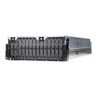
Seagate Exos CORVAULT 4U106 Replacing (3 pages)
Replacing a drive module in its carrier for a 4U enclosure

Seagate Exos CORVAULT 4U106 Replacing (2 pages)
Main bay cover replacement in a 4U enclosure
Advertisement
Seagate Exos CORVAULT 4U106 Getting Started (2 pages)
Brand: Seagate
|
Category: Computer Hardware
|
Size: 0 MB

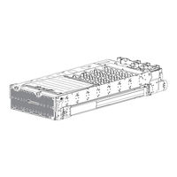
Seagate Exos CORVAULT 4U106 Replacing (2 pages)
Replacing a 4U SAS Expander Module