
Related Manuals for Eaton 93PM IBC-SW


Summary of Contents for Eaton 93PM IBC-SW
- Page 1 Eaton® 93PM Integrated Battery Cabinet-Small Welded IBC-SW Installation Manual p/n: 164000639 Revision 07...
- Page 2 National Fire Protection Association, Inc. ERIFLEX and FLEXIBAR are registered trademark of Erico International Corporation. All other trademarks are property of their respective companies. ©Copyright 2017-2024 Eaton, Raleigh, NC, USA. All rights reserved. No part of this document may be reproduced in any way without the express written approval of Eaton.
- Page 3 3.2.2 IBC-SW Power Wiring Preparation......................15 3.2.3 IBC-SW Interface Wiring Preparation ...................... 17 3.3 Inspecting and Unpacking the Eaton 93PM IBC-SW ..................18 3.4 Battery Breaker Location ..........................21 4 4 I I n n s s t t a a l l l l a a t t i i o o n n ..........................................................2 2 2 2 4.1 Preliminary Installation Information.......................
-
Page 4: Table Of Contents
8 8 W W a a r r r r a a n n t t y y ............................................................7 7 0 0 Eaton 93PM Integrated Battery Cabinet-Small Welded (IBC-SW) Installation Manual 164000639—Rev 07... - Page 5 Eaton 93PM IBC-SW Center of Gravity ..................... 14 Figure 6. Eaton 93PM IBC-SW as Shipped on Pallet ..................20 Figure 7. Eaton 93PM IBC-SW Battery Breaker Location – Front View with Cover Removed ........21 Figure 8. Removing the Pallet Skids and Supports ................... 25 Figure 9.
- Page 6 IBC-SW Cabinet Weights ........................ 11 Table 3. IBC-SW Cabinet Clearances......................12 Table 4. Line-Up-and-Match External Power Wiring Recommendations: Eaton 93PM IBC-SW (432V or 480V) ....16 Table 5. Standalone External Power Wiring Recommendations: Eaton 93PM IBC-SW (432V or 480V) ......16 Table 6.
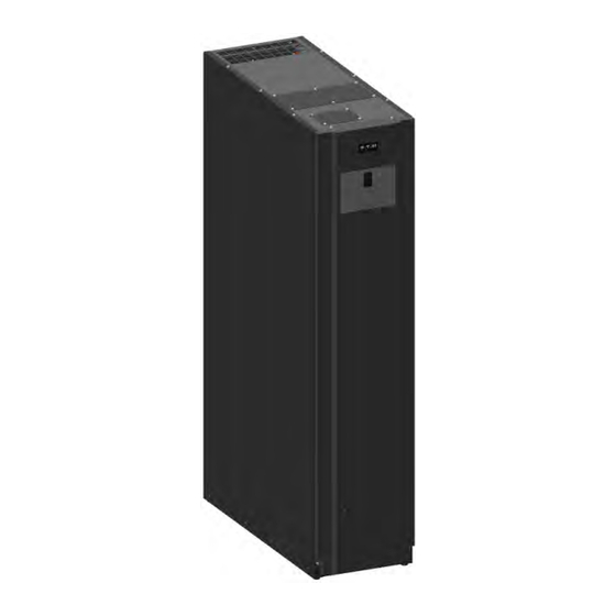
- Page 7 Warranty for details. This service is offered as part of the sales contract for the UPS. Contact an Eaton service representative in advance (a minimum two-week notice is required) to reserve a preferred startup date. Figure 1. Eaton 93PM Integrated Battery Cabinet–Small Welded...
- Page 8 Line-up-and-match battery cabinets are installed adjacent to the UPS. The IBC-SW can be installed on either the left or right side or on both sides of the UPS cabinet (see Figure Figure 2. Eaton 93PM UPS and Two 93PM IBC-SWs — Various Configurations Left Side IBC-SW Installation Right Side IBC-SW Installation...
-
Page 9: Table 1. Optional Thermal Sensor Specifications
Screen type represents information that appears on the screen or LCD. Description Icon Note Information notes call attention to important features or instructions. [Keys] Brackets are used when referring to a specific key, such as [Enter] or [Ctrl]. Eaton 93PM Integrated Battery Cabinet-Small Welded (IBC-SW) Installation Manual 164000639—Rev 07... - Page 10 Eaton 93PM UPS 480V Three-Wire – 50 kW Frame Installation and Operation Manual ECopyright 2008–2010 Eaton Corporation, Raleigh, NC, USA. All rights reserved. No part of this document may be Phillips and Pozidriv are registered trademarks of Phillips Screw Company.
- Page 11 Communication capabilities of the UPS system. Visit www.eaton.com/powerquality or contact an Eaton service representative for information on how to obtain copies of these manuals. 1 1 . . 8 8 G G e e t t t t i i n n g g H H e e l l p p If help is needed with any of the following: •...
-
Page 12: Important Safety Instructions
Do not check UPS operation by any action that includes removal of the earth (ground) connection with loads attached. • Do not open or mutilate batteries. Released electrolyte is harmful to the skin and eyes. It may be toxic. Eaton 93PM Integrated Battery Cabinet-Small Welded (IBC-SW) Installation Manual 164000639—Rev 07... - Page 13 The operating environment should be maintained within the parameters stated in this manual. • Keep surroundings uncluttered, clean, and free from excess moisture. • Observe all DANGER, CAUTION, and WARNING notices affixed to the inside and outside of the equipment. Eaton 93PM Integrated Battery Cabinet-Small Welded (IBC-SW) Installation Manual 164000639—Rev 07...
- Page 14 End forklift slots may be used for minor positioning if the forks are kept in a horizontal position with no upward angling. If these instructions are not followed, damage to the wiring channel and wiring will occur. Eaton 93PM Integrated Battery Cabinet-Small Welded (IBC-SW) Installation Manual 164000639—Rev 07...
- Page 15 Les passages de fourche à l’extrémité de l’armoire peuvent servir lors des petits déplacements, et ce, si les fourches sont en position horizontale sans pointer vers le haut. Si ces instructions ne sont pas suivies, des dommages au câblage et à son canal surviendront. Eaton 93PM Integrated Battery Cabinet-Small Welded (IBC-SW) Installation Manual 164000639—Rev 07...
- Page 16 C C h h a a p p t t e e r r 3 3 I I n n s s t t a a l l l l a a t t i i o o n n P P l l a a n n a a n n d d U U n n p p a a c c k k i i n n g g Use the following basic sequence of steps to install the Eaton 93PM Integrated Battery Cabinet: Create an installation plan for the IBC.
-
Page 17: Models
25°C (77°F). Operating temperatures above the recommended range will result in decreased battery life and performance, and will reduce or void the battery warranty. Refer to Eaton's Terms and Conditions of Sale with Battery Replacement Coverage and the Battery Replacement Price Book for more information. -
Page 18: Table 3. Ibc-Sw Cabinet Clearances
203.2 mm (8") minimum clearance From Right Side of Cabinet None Required None Required From Left Side of Cabinet Figure 3. Eaton 93PM IBC-SW Dimensions (Front, Right Side, and Rear Views) [3.1] [13.4] [5.9] Covered by a plate when configured... - Page 19 Installation Plan and Unpacking Figure 4. Eaton 93PM IBC-SW Dimensions (Top and Bottom Views) [1.2] [13.4] [4.0] [5.9] [32.8] Covered by a plate when configured for rear ventilation [29.8] [5.3] [5.4] [5.9] [2.7] [6.5] Dimensions are in millimeters [inches] Eaton 93PM Integrated Battery Cabinet-Small Welded (IBC-SW) Installation Manual 164000639—Rev 07...
- Page 20 979.5 [2159] Batteries 93PM IBC-SW with no batteries 899 [35.4] 542 [21.3] 214 [8.4] 274.3 [605] 93PM IBC-SW with no batteries 902 [35.5] 541 [21.3] 214 [8.4] 275.5 [607] Eaton 93PM Integrated Battery Cabinet-Small Welded (IBC-SW) Installation Manual 164000639—Rev 07...
- Page 21 • Each battery cabinet has its own overcurrent protection device. • Internal battery strings are to be connected by an authorized Eaton Customer Service Engineer. • Refer to the appropriate Eaton 93PM UPS Installation and Operation manual listed in paragraph 1.7 For...
-
Page 22: Table 4. Line-Up-And-Match External Power Wiring Recommendations: Eaton 93Pm Ibc-Sw (432V Or 480V)
4. For standalone external power wiring requirements, including the minimum AWG size of external wiring, see Table 5. Wire sizes listed are for copper wiring only. Table 4. Line-Up-and-Match External Power Wiring Recommendations: Eaton 93PM IBC-SW (432V or 480V) Battery Cabinet to UPS Minimum Recommended... -
Page 23: Table 6. External Power Cable Terminations For The Eaton 93Pm Ibc-Sw
Installation Plan and Unpacking Table 6. External Power Cable Terminations for the Eaton 93PM IBC-SW Tightening Screw Size Terminal Number and Size of Torque Nm (lb in) and Type Model Function Terminal Function Pressure Termination Battery + Positive 2 - #6-250 kcmil 31 (275) 5/16"... - Page 24 Suivre attentivement les instructions de déchargement et de déballage pour eviter de renverser les armoires, ce qui pourrait causer de graves blessures. Carefully inspect the outer packaging for evidence of damage during transit. Do not install a damaged cabinet. Report any damage to the carrier and contact an Eaton service representative immediately. ATTENTION! Ne pas installer une armoire endommagée.
- Page 25 Inspect the contents for any evidence of physical damage, and compare each item with the Bill of Lading. If damage has occurred or shortages are evident, contact an Eaton service representative immediately to determine the extent of the damage and its impact on further installation.
- Page 26 Installation Plan and Unpacking Figure 6. Eaton 93PM IBC-SW as Shipped on Pallet Eaton 93PM Integrated Battery Cabinet-Small Welded (IBC-SW) Installation Manual 164000639—Rev 07...
- Page 27 93PM Integrated Battery Cabinet–Small Welded with the front cover removed. Figure 7. Eaton 93PM IBC-SW Battery Breaker Location – Front View with Cover Removed Battery Breaker Eaton 93PM Integrated Battery Cabinet-Small Welded (IBC-SW) Installation Manual 164000639—Rev 07...
- Page 28 Lift the cabinets only with a forklift or pallet jack or damage may occur. • Ensure forklift is rated to handle the weight of the cabinet. Failure to follow these instructions may result in severe injury or death. Eaton 93PM Integrated Battery Cabinet-Small Welded (IBC-SW) Installation Manual 164000639—Rev 07...
- Page 29 Ne retirez pas et ne desserrez pas les boulons de montage ou de support de l'armoire avant d'y être invité. Loosen, but do not remove, the skid mounting bolts holding the front and rear supports to the pallet skids. Eaton 93PM Integrated Battery Cabinet-Small Welded (IBC-SW) Installation Manual 164000639—Rev 07...
- Page 30 (maximum) until the casters contact the floor and the cabinet is no longer supported by the jacking bolts. After the IBC is resting on the floor, remove the jacking bolts and floor protectors. Recycle them in a responsible manner. Eaton 93PM Integrated Battery Cabinet-Small Welded (IBC-SW) Installation Manual 164000639—Rev 07...
- Page 31 To prevent tipping when rolling the cabinet, push the cabinet from the rear whenever possible. ATTENTION! Pour éviter de basculer lorsque vous faites rouler l'armoire, poussez-la autant que possible par l'arrière. Eaton 93PM Integrated Battery Cabinet-Small Welded (IBC-SW) Installation Manual 164000639—Rev 07...
- Page 32 26. If the IBC was ordered with the batteries and battery trays shipped separately, proceed to paragraph Installing Shipped-Separate Batteries and Battery Trays; otherwise, proceed to paragraph 4.4 Installing Power Wiring. Eaton 93PM Integrated Battery Cabinet-Small Welded (IBC-SW) Installation Manual 164000639—Rev 07...
- Page 33 Inter-cabinet wiring access to route interface wiring between cabinets. Inter-cabinet wiring access knockouts. Remove knockouts as required to route power wiring between cabinets. Left Side View Right Side View Eaton 93PM Integrated Battery Cabinet-Small Welded (IBC-SW) Installation Manual 164000639—Rev 07...
- Page 34 Installation Figure 10. Rear Ventilation Front Ventilation Grill Top View Back View Cover Plate Eaton 93PM Integrated Battery Cabinet-Small Welded (IBC-SW) Installation Manual 164000639—Rev 07...
- Page 35 Installation Figure 11. Top Ventilation Front Cover Plate Top View Back View Ventilation Grill Eaton 93PM Integrated Battery Cabinet-Small Welded (IBC-SW) Installation Manual 164000639—Rev 07...
- Page 36 Perform a visual inspection for shipping damage. Record the Replacement Battery Date code. Record any deficiencies. If damage has occurred or shortages are evident, contact an Eaton service representative immediately to determine the extent of the damage and its impact on further installation (see 1.8 Getting Help).
- Page 37 If the tray is for a 432V IBC-SW top tray location, install 12 bumpers in the front section of the tray. Route the strapping through the holes in the tray, see Figure 13 for strapping layout detail. Eaton 93PM Integrated Battery Cabinet-Small Welded (IBC-SW) Installation Manual 164000639—Rev 07...
- Page 38 Place batteries in the front of the tray, ensure terminal locations are identical to the layout detailed in Figure N N O O T T E E The battery numbering in this section is for ease of installation. Eaton 93PM Integrated Battery Cabinet-Small Welded (IBC-SW) Installation Manual 164000639—Rev 07...
- Page 39 Batteries #2 and #4 in the front of the tray. Remove excess strapping material. 11. Place batteries in the rear of the tray, ensure terminal locations are identical to the layout detailed in Figure Eaton 93PM Integrated Battery Cabinet-Small Welded (IBC-SW) Installation Manual 164000639—Rev 07...
- Page 40 14. Attach the positive double wiring harness to the positive terminal on Battery #1 at the front of the tray using the M6 bolt, lock washer, flat washer and 2 QIK tabs, see Figure 16 Figure Eaton 93PM Integrated Battery Cabinet-Small Welded (IBC-SW) Installation Manual 164000639—Rev 07...
- Page 41 (qty 1) M6 Lock Washer M6 Flat Washer 15. Using 2 nylon wire retainers, secure the positive cabling to the battery tray, see Figure 16 for wire retainer location. Eaton 93PM Integrated Battery Cabinet-Small Welded (IBC-SW) Installation Manual 164000639—Rev 07...
- Page 42 Install the connections using a M6 bolt, lock washer, flat washer and 1 QIK tab. Figure 19 for 1 QIK Tab and 2 QIK Tab locations. Eaton 93PM Integrated Battery Cabinet-Small Welded (IBC-SW) Installation Manual 164000639—Rev 07...
- Page 43 23. Connect the Positive double wiring harness gray connector to the Negative double wiring harness connector. 24. Using the battery tray lift, install the completed battery tray into the IBC, lowest install location. Eaton 93PM Integrated Battery Cabinet-Small Welded (IBC-SW) Installation Manual 164000639—Rev 07...
- Page 44 26. Repeat these steps to prepare the rest of the battery trays, and install the completed trays into the IBC working from lowest to uppermost tray location. Figure 20. Complete Battery Tray Detail Insulator IBC-SW FULL BATTERY TRAY Eaton 93PM Integrated Battery Cabinet-Small Welded (IBC-SW) Installation Manual 164000639—Rev 07...
- Page 45 N N O O T T E E 2 2 Up to four IBC-SWs can be installed in a line-up-and-match configuration. Use this procedure to wire line-up-and-match 93PM Integrated Battery Cabinets to the 93PM UPS cabinet. Eaton 93PM Integrated Battery Cabinet-Small Welded (IBC-SW) Installation Manual 164000639—Rev 07...
- Page 46 Installation To install wiring to connections: Verify the UPS system is turned off and all power sources are removed. Refer to the applicable Eaton 93PM UPS Installation and Operation manual, listed in paragraph 1.7 For More Information, for UPS operating procedures.
- Page 47 Installation Figure 22. Wiring Channel Location Wiring Channel Eaton 93PM Integrated Battery Cabinet-Small Welded (IBC-SW) Installation Manual 164000639—Rev 07...
- Page 48 Installation Figure 23. DC Power Terminal Locations DC Output Terminals + and – Ground Terminals Eaton 93PM Integrated Battery Cabinet-Small Welded (IBC-SW) Installation Manual 164000639—Rev 07...
- Page 49 Figure 25. DC Power Terminal Detail IBC–SW DC (+) Output to UPS Positive Terminals (+) Wire Tie Anchors IBC–SW DC (–) Output to UPS Negative Terminals (–) Battery Breaker Eaton 93PM Integrated Battery Cabinet-Small Welded (IBC-SW) Installation Manual 164000639—Rev 07...
- Page 50 Use this procedure to wire standalone 93PM Integrated Battery Cabinets to the 93PM UPS cabinet. To install wiring to connections: Verify the UPS system is turned off and all power sources are removed. Refer to the applicable Eaton 93PM UPS Installation and Operation manual, listed in paragraph 1.7 For More...
- Page 51 Figure 18. Connect the ground, positive, and negative DC power wiring from the IBC-SW or disconnect to the UPS cabinet battery and ground terminals. Refer to the applicable Eaton 93PM UPS Installation and Operation manual listed in paragraph 1.7 For More Information, for UPS cabinet termination requirements.
- Page 52 N N O O T T E E In multiple IBC-SW installations, route the battery interface wiring between IBC-SWs through the top of the adjacent IBC-SW using the top side inter-cabinet access pass- through (see Figure Eaton 93PM Integrated Battery Cabinet-Small Welded (IBC-SW) Installation Manual 164000639—Rev 07...
- Page 53 Table Figure 28, and Figure 29 for wiring and termination requirements. Refer to the applicable Eaton 93PM UPS Installation and Operation manual listed in paragraph 1.7 For More Information, for UPS cabinet terminal locations. Proceed to Step 10. Top Entry Wiring. Remove the top conduit plate (see Figure 26) from the top of the IBC-SW.
- Page 54 Secure the top of the cover with the two retained mounting bolts and tighten the bottom bolts. 14. Once the battery cabinets are installed and wired, return to the applicable Eaton 93PM UPS Installation and Operation manual, listed in paragraph 1.7 For More...
-
Page 55: Table 8. Ibc Tb2 Interface Connections
#26–#16 0.4 (3.5) - 0.8 (7.1) Slotted Use #18 AWG twisted-pair wires for each input and return or common. Strip wire insulation back 10 millimeters to wire terminal blocks. Eaton 93PM Integrated Battery Cabinet-Small Welded (IBC-SW) Installation Manual 164000639—Rev 07... - Page 56 93PM-L (208V) UPS 60kW and 120kW frame sizes and at the right side of the static switch, inside the wireway, of the 93PM-L (208V) USPS 160kW and 200kW]. NOTE 5 The Thermal Sensor is optional. Eaton 93PM Integrated Battery Cabinet-Small Welded (IBC-SW) Installation Manual 164000639—Rev 07...
- Page 57 93PM-L (208V) UPS 60kW and 120kW frame sizes and at the right side of the static switch, inside the wireway, of the 93PM-L (208V) USPS 160kW and 200kW]. NOTE 5 The Thermal Sensor is optional. Eaton 93PM Integrated Battery Cabinet-Small Welded (IBC-SW) Installation Manual 164000639—Rev 07...
- Page 58 N N O O T T E E In multiple IBC-SW installations, route the battery interface wiring between IBC-SWs through the top of the adjacent IBC-SW using the top side inter-cabinet access pass- through (see Figure Eaton 93PM Integrated Battery Cabinet-Small Welded (IBC-SW) Installation Manual 164000639—Rev 07...
- Page 59 Table Figure 28, and Figure 29 wiring and termination requirements. Refer to the applicable Eaton 93PM UPS Installation and Operation manual listed in paragraph 1.7 For More Information, for UPS cabinet terminal locations. Secure the interface wiring to the wire tie anchors (see Figure 24) using Zip ties.
- Page 60 Secure the top of the cover with the two retained mounting bolts and tighten the bottom bolts. 15. Once the battery cabinets are installed and wired, return to the applicable Eaton 93PM UPS Installation and Operation manual, listed in paragraph 1.7 For More...
- Page 61 Installation requirements. Refer to the applicable Eaton 93PM UPS Installation and Operation manual listed in paragraph 1.7 For More Information, for UPS cabinet terminal locations. Proceed to Step 10. Bottom Entry Wiring. Remove the bottom conduit plate (see Figure 26) from the inside bottom of the IBC-SW.
- Page 62 Connect the positive connector to the fixed negative connector on the front edge of the battery tray above it, see Figure 31 for a detailed view of the battery tray to cabinet connections. Eaton 93PM Integrated Battery Cabinet-Small Welded (IBC-SW) Installation Manual 164000639—Rev 07...
- Page 63 Install the front door (previously removed) by carefully lowering the door onto the bottom screws. Secure the top of the door with the two retained screws and tighten the bottom screws. Once the battery cabinets are installed and wired, return to the applicable Eaton 93PM UPS Installation and Operation manual, listed in paragraph 1.7 For More...
- Page 64 Make a copy of the Installation Checklist before filling it out, and retain the original. After the installation is complete, an Eaton Customer Service Engineer must verify the operation of the UPS system and commission it to support the critical load. The service representative cannot perform any installation tasks other than verifying software and operating setup parameters.
- Page 65 Installation Notes _________________________________________________________________________ _________________________________________________________________________ _________________________________________________________________________ _________________________________________________________________________ _________________________________________________________________________ _________________________________________________________________________ _________________________________________________________________________ _________________________________________________________________________ _________________________________________________________________________ _________________________________________________________________________ _________________________________________________________________________ _________________________________________________________________________ _________________________________________________________________________ _________________________________________________________________________ _________________________________________________________________________ Eaton 93PM Integrated Battery Cabinet-Small Welded (IBC-SW) Installation Manual 164000639—Rev 07...
- Page 66 Battery Cabinet 4 Four Battery Cabinets Maximum N N O O T T E E Three and four battery cabinet wiring assumes using factory supplied wiring and one wire per pole. Eaton 93PM Integrated Battery Cabinet-Small Welded (IBC-SW) Installation Manual 164000639—Rev 07...
- Page 67 Battery Cabinet 3 Battery Cabinet 4 N N O O T T E E External tie point, battery breaker or disconnect, and wiring to be supplied by the customer. Eaton 93PM Integrated Battery Cabinet-Small Welded (IBC-SW) Installation Manual 164000639—Rev 07...
- Page 68 93PM-L (208V) UPS 60kW and 120kW frame sizes and at the right side of the static switch, inside the wireway, of the 93PM-L (208V) USPS 160kW and 200kW.] Eaton 93PM Integrated Battery Cabinet-Small Welded (IBC-SW) Installation Manual 164000639—Rev 07...
- Page 69 S S c c h h e e m m a a t t i i c c s s Figure 36 Figure 37 show the 93PM Integrated Battery Cabinet schematics. Figure 36. 93PM Integrated Battery Cabinet Schematic Eaton 93PM Integrated Battery Cabinet-Small Welded (IBC-SW) Installation Manual 164000639—Rev 07...
- Page 70 Onelines and Schematics Figure 37. 93PM Integrated Battery Cabinet — Battery String Detail Schematic Eaton 93PM Integrated Battery Cabinet-Small Welded (IBC-SW) Installation Manual 164000639—Rev 07...
- Page 71 Ensure the air intakes on the Accessory cabinets are not blocked. Ensure the operating environment is within the parameters specified in paragraph 3.2.1 Environmental and Installation Considerations and Chapter 7 Product Specifications. Eaton 93PM Integrated Battery Cabinet-Small Welded (IBC-SW) Installation Manual 164000639—Rev 07...
- Page 72 6 6 . . 2 2 . . 3 3 A A N N N N U U A A L L M M a a i i n n t t e e n n a a n n c c e e Annual preventive maintenance should be performed only by authorized service personnel familiar with maintenance and servicing of the UPS system. Contact an Eaton service representative for more information about service offerings.
- Page 73 M M a a i i n n t t e e n n a a n n c c e e T T r r a a i i n n i i n n g g A basic training course, available from Eaton, gives you a competent working knowledge of the UPS system operation and teaches you how to perform first level corrective maintenance.
-
Page 74: Specifications
Must be replaced by a qualified service technician Protection IBC-SW output protected by 250A circuit breaker. Battery Shelf Life 8 Months from the date code on the battery (stored at room temperature) Eaton 93PM Integrated Battery Cabinet-Small Welded (IBC-SW) Installation Manual 164000639—Rev 07... - Page 75 5 to 95%, noncondensing Relative Humidity (operating and storage) Acoustical Noise Not applicable Safety Conformance UL1778 5 edition Agency Markings cULus FCC Part 15 Class A and 62040-2 C3 EMC (Class A) Eaton 93PM Integrated Battery Cabinet-Small Welded (IBC-SW) Installation Manual 164000639—Rev 07...
- Page 76 C C h h a a p p t t e e r r 8 8 W W a a r r r r a a n n t t y y To view the UPS warranty please click on the link or copy the address to download from the Eaton website: UPS Product Warranty https://www.eaton.com/content/dam/eaton/products/backup-power-ups-surge-it-power-distribution/backup-...
- Page 78 16400063907 164000639 07...
Need help?
Do you have a question about the 93PM IBC-SW and is the answer not in the manual?
Questions and answers