
Subscribe to Our Youtube Channel
Related Manuals for Eaton 912 -IS Series


Summary of Contents for Eaton 912 -IS Series
- Page 1 Instruction manual April 2020 MTL fieldbus networks INM9120 Rev 8 NET9000 Fieldbus Connections 912x-IS FISCO power supplies...
-
Page 2: Declaration Of Conformity
Declaration of Conformity A printed version of the Declaration of Conformity has been provided separately within the original shipment of goods. However, you can find a copy of the latest version at http://www.mtl-inst.com/certificates INM9120 Rev 8... -
Page 3: Table Of Contents
CONTENTS DECLARATION OF CONFORMITY . . . . . . . . . . . . . . . . . . . . . . . . . . . . . . . . . . . . . . . . . . . . . . . . . . . . . . II ABOUT THIS MANUAL . - Page 4 This page is left intentionally blank INM9120 Rev 8...
-
Page 5: About This Manual
ABOUT THIS MANUAL The purpose of this manual is to provide the user with information on the installation, connection, test and maintenance of the MTL912X range of Fieldbus Intrinsically Safe COncept (FISCO) power supplies. Cautionary Note: In common with all other electrical apparatus installed in hazardous areas, this apparatus must only be installed, operated and maintained by competent personnel. -
Page 6: Installation
INSTALLATION 2 .1 MOUNTING & ENCLOSURE REQUIREMENTS 2 .1 .1 General These power supplies may be mounted in safe areas, Zone 2 hazardous areas but, wherever they are located, the mounting conditions must: (a) maintain safe segregation distances for units and IS wiring. (b) prevent any form of pollution that could compromise the operation, or safety of the unit. -
Page 7: Mounting
2 .2 MOUNTING 2 .2 .1 Orientation The 912x range of power supplies can be mounted on type T35 [top hat] DIN-rail, or surface mounted. In either case, the orientation must allow air to be naturally convected through the unit to achieve the maximum cooling effect. - Page 8 To remove a unit from the rail, insert a screwdriver blade into the clip as shown in figure 3 and lever the clip gently outwards; pivot the isolator off the rail. Figure 3 - Removing from DIN rail 2 .2 .3 Surface mounting FISCO power supplies To surface mount a 912X - IS power supply, ease out the DIN rail clips at each end (in the manner shown in Figure 3) to reveal mounting brackets, which contain clearance holes for M4 screws or bolts.
-
Page 9: Signal And Power Connections
2 .3 SIGNAL AND POWER CONNECTIONS 2 .3 .1 General All units have removable signal and power plugs. The plugs can be supplied with either screw-clamp (912X–IS–PS) or sprung cage-clamp (912X–IS–PC) terminals as shown in figure 5. Figure 5 - Spring clamp and screw clamp plugs. The user can decide whether it will be easier to wire the power supply with the connector plugs in- situ, or to remove them. -
Page 10: Making Connections
2 .3 .2 Host and IS fieldbus connections The block diagram (Figure 7) shows terminals 5 and 8 marked with an ‘S’. This indicates a termination point for the fieldbus cable screen. These are termination points only, with no internal connection. Power In 19.2 to 30V Host Fieldbus... -
Page 11: Setup And Testing
SETUP AND TESTING 3 .1 SWITCHES Two switches are provided on the front face of the power supply, located in the top right-hand corner. Operation of these switches requires the use of a small screwdriver, or similar Figure 8 - Host power supply and host trunk terminator 3 .1 .1 “Host Pwr”... -
Page 12: Tag Labelling
MAINTENANCE IMPORTANT NOTE If any power supply is suspected of being faulty, return it to Eaton’s MTL product line, or the representative from whom it was purchased, for repair or replacement. DO NOT make repairs or modifications. The safe operation of the unit, and hence the safety of the site, can be affected by unauthorised changes. -
Page 13: Appendix A - Atex Information
APPENDIX A - ATEX INFORMATION The Essential Health and Safety Requirements (Annex II) of the EU Directive 2014/34/EU [the ATEX Directive - safety of apparatus] requires that the installation manual of all equipment used in hazardous areas shall contain certain information. This annex is included to ensure that this requirement is met. It compliments the information presented in this document and does not conflict with that information. -
Page 14: Marking
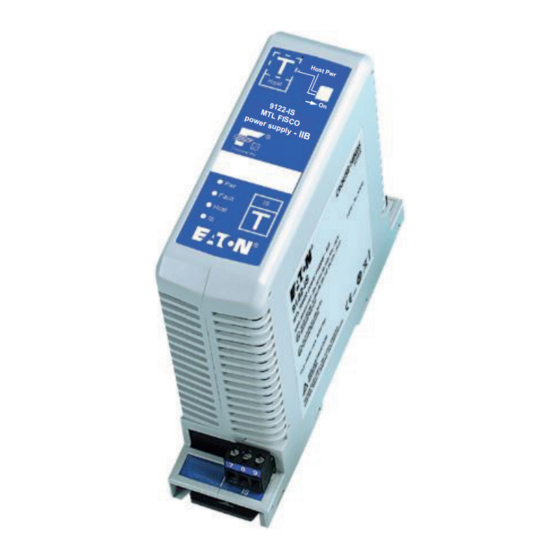
MTL02ATEX9121X TC RU C-GB.ME92.B.00739 19.2 - 30Vdc 6.6W Max SEE INSTRUCTION MANUAL EU Importer - Eaton, 69412 Eberbach, Germany EATON ELECTRIC LTD, Luton, England, 0598 LU2 8DL. Made in England. www.mtl-inst.com 9122-IS MTL FISCO power supply - IIB -40°C Ta +70°C Power In Um 40Vdc IECEx BAS04.0031X [Ex ib Gb] IIB [Ex ib Db] IIIC... - Page 15 This page is left intentionally blank INM9120 Rev 8...
- Page 16 This page is left intentionally blank INM9120 Rev 8...
- Page 17 This page is left intentionally blank INM9120 Rev 8...
- Page 18 AUSTRALIA NORWAY Eaton Electrical (Australia) Pty Ltd, Norex AS 10 Kent Road, Mascot, New South Wales, 2020, Australia Fekjan 7c, Postboks 147 , N-1378 Nesbru, Norway Tel: +61 1300 308 374 Fax: +61 1300 308 463 E-mail: mtlsalesanz@eaton.com Tel: +47 66 77 43 80 Fax: +47 66 84 55 33 E-mail: info@norex.no...
Need help?
Do you have a question about the 912 -IS Series and is the answer not in the manual?
Questions and answers