Table of Contents
Advertisement
Quick Links
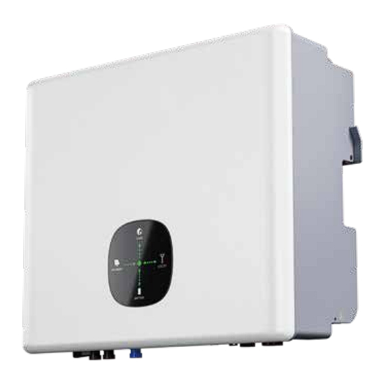
THREE-PHASE
HYBRID INVERTER
H����H-EU / H�����H-EU / H�����H-EU
Dongguan Hinen New Energy Technology Co., Ltd
Add: No.�� Dongkang Road, Dalingshan Town, Dongguan City,
Guangdong Province, China
Tel: +�� (���) �������� ext ����
Email: service@hinen.com
Website: https://www.hinen.com
Europe HL Hinen B.V.
User Manual
Add: John M. Keynesplein �, ����EP Amsterdam
Tel: +�� (���) �������� ext ����
Email: service@hinen.com
Website: https://eu.hinen.com
Advertisement
Table of Contents

Related Manuals for Hinen H8000-EU


Summary of Contents for Hinen H8000-EU
- Page 1 THREE-PHASE HYBRID INVERTER H����H-EU / H�����H-EU / H�����H-EU Dongguan Hinen New Energy Technology Co., Ltd Add: No.�� Dongkang Road, Dalingshan Town, Dongguan City, Guangdong Province, China Tel: +�� (���) �������� ext ���� Email: service@hinen.com Website: https://www.hinen.com Europe HL Hinen B.V.
- Page 2 · Incompatible batteries, loads, or other devices are connected to the inverter system.tem. The manual cannot include complete information about the photovoltaic (PV) system. The reader can get additional information about other devices at https://www.hinen.com or on the webpage of the respective component manufacturer.
- Page 3 Symbol Definition and Explanation Safety warning Warning! Any installation and operation must be carried out by a qualified electrician in accordance with local grid or company standards, wiring rules or requirements. Failure to follow the warning signs in this manual could result in personal injury. Before doing any wiring or electrical work on the inverter, all batteries and AC power must be High voltage and electric shock hazard! disconnected from the inverter for at least �...
-
Page 4: Table Of Contents
Contents �. � Connection Ground Fault Alarm �� �.�.�. Inverter Ground Fault �� �.�.�. External Inverter Ground Faults �� �. Introduction �. � Battery Terminal Wiring �� �.� Introduction to Operating Modes � �. � .� Battery Connection Mode �� �.�... -
Page 5: Introduction
�. Introduction The inverter is a hybrid or bidirectional solar inverter, suitable for solar systems involving PV, batteries, loads, and grid systems for energy management. The energy generated by the photovoltaic system can be used to optimize household electricity consumption; the excess energy is used to charge the battery, and the remaining energy is exported to the grid. -
Page 6: Introduction To Operating Modes
�.� Introduction to Operating Modes Light Board Display : Light Board Display : Mode � Mode � According to different system configurations and layouts, the inverter can usually beset to the following When the grid is powered off, operating modes. The grid and photovoltaic system automatically... -
Page 7: Specifications Parameters
�.� Specifications Parameters ~�(�.�leading - �.�lagging) Power factor <�% THDI @Full load H����H-EU H�����H-EU H�����H-EU Model ��A AC inrush current PV Input Data MAX. output ��A Max. recommended �����W �����W �����W overcurrent protection PV power AC maximum output ��A ����V Max. -
Page 8: Installation Descriptions
� . Installation Descriptions General Data Transformerless �.� Examples of Incorrect Installation Topology ���*���*���mm Dimensions(W/H/D) Ensure the installation follows these guidelines to avoid incorrect setups: · The off-grid port cannot be connected in parallel. If necessary, please contact after-sales support. ��.�kg Weight ·... -
Page 9: System Wiring Diagram
�.� System Wiring Diagram Schematic representation of grid systems with no special requirements for electrical connections The energy storage inverter wiring system Note: the off-grid ground wire and ground bar must be properly connected to work properly. Otherwise, the off-grid function may be abnormal when the grid fails. ��... -
Page 10: Packing List
�.� Packing List Model � � � � � Upon receiving the hybrid inverter, please check if any of the components as shown below are missing or ��A, ≥���V ��A/���V ��A/���V, �L/N/PE ��mA RCD (Type A), H����H-EU main breaker broken. DC breaker AC breaker ��mA RCD (Type A) -
Page 11: Installation
�.� Installation �.�.� Select Mounting Location �.�.� Installation Tools For inverter's protection and convenient maintenance, mounting location for inverter should be selected carefully based on the following rules. Recommended installation tools include but are not limited to the following tools. If necessary, additional auxiliary tools can be used on site. -
Page 12: Mounting The Inverter
�.�.� Mounting the Inverter Rule �. The mounting structure where the inverter is installed must comply with local/national standards and guidelines. Ensure that the installation surface is solid enough to bear four times the weight of the inverter and is suitable for the dimensions of the inverter(e.g. cement walls, plasterboard walls, etc.). -
Page 13: Electrical Connections
�.�.� PV Wiring Connection �.� Electrical Connections Before connecting PV panels/strings to the inverter, ensure all the following requirements are met: �.�.� Connect the PV Input Line �. The total short-circuit current of a PV string must not exceed the inverter's max DC current. Connect the PE cable to the grounding plate at the grid side. -
Page 14: Connect The Battery Cable
�.�.� Connect the Battery Cable � Be aware of electrical shock hazards or chemical hazards. If the battery does not have a built-in DC circuit breaker, please ensure that an external DC circuit breaker (≥��A) is connected. Note: You will hear a "click"... - Page 15 � � Notice: If the battery port is not used, install a dust cap to prevent rain and dust from entering the inverter. · Thread the cable through the cable gland and insert the crimp contact into the insulator. A clicking sound indicates that it has snapped into place.
-
Page 16: On-Grid & Off-Grid Connection
�.�.� On-grid & Off-grid Connection �.�.�.� Off-grid Connection When the inverter is connected to the grid, add an external AC circuit breaker to isolate the grid from The inverter supports both on-grid and off-grid functions. It will transmit power through the on-grid port the inverter if necessary. -
Page 17: On-Grid Connection
� Align the square opening on the AC load connector with the foot buckle on the inverter off-grid port Notice: and insert. If the off-grid port is not used, please install a dust plug for the AC load connector to prevent rain and The foot buckle entering the grid terminal and exposing the upper opening followed by a "click"... - Page 18 � Insert the cable conductor core into the terminal and crimp. Ensure that the cable sheath is not Notice: locked into the connector. · All electrical connections must be in accordance with local and national standards. · Only with the permission of the local utility grid company, the inverter can be connected to the utility Thread an appropriate length of AC cable through the waterproof terminal.
-
Page 19: Connecting The Smart Meter
Declarations for The Back-up Function �.�.� Connecting the Smart Meter The backup output of the hybrid inverters has overload capability. The inverter also has self-protection derating at high ambient temperatures. Ensure the AC cable is fully isolated from the AC power source before connecting the smart meter. �. - Page 20 Smart meter wiring diagram Item User interface ��� means table address Item User interface Description combined power A phase voltage=���.�V � �� Note: Please be sure to wire according to the above wiring rules, otherwise, the inverter will factor PFt=�.��� not operate normally.
-
Page 21: Connection Ground Fault Alarm
Note: When the smart meter is used with this product, the current ratio is set to ��, and the voltage ratio Item Color CAN(BMS) � � � � is set to �.�. � WAKE_UP � � � � range and white �... -
Page 22: Connect Wifi Module
�.�.� Logger Status �.� Connect WIFI Module Check Indicator light The WIFI communication function is only applicable to the WIFI module, please refer to the following figure to install the WiFi module Lights Implication Status Description(All lights are single green lights.) �.Light off: Connection to the router failed. -
Page 23: Abnormal State Troubleshooting
�.�.� Abnormal State Troubleshooting �.� The Connection Mode of COM If the data on platform is abnormal when the stick logger is running, please check the table below and according to the status of indicator lights to complete a simple troubleshooting. If it still can not be resolved or indicator lights status do not show in the table below, please contact Customer Support. -
Page 24: Commissioning
�. Commissioning Photovoltaic Module Access Requirements �. Modules with consistent photovoltaic characteristics should be used for connection under the same MPPT. �.� Inspection before Commissioning �. Ensure the number of photovoltaic modules connected under the same MPPT is consistent; the number of modules connected to different MPPTs cannot exceed one. -
Page 25: Electrical Inspection
�.�.� Electrical inspection Checking Method for String Grounding ·Turn the multimeter to the DC voltage position. Put the red test lead on the measured cable and the black Observe the lable of the three-phase inverter. When wiring, electrical inspection should be cartied out to test lead on the ground terminal. -
Page 26: Powering On The System
·In the picture on the right, the multimeter shows that the current battery voltage is ���V. The red test lead is connected to the positive pole, and the black test lead is connected to the negative pole, indicating correct polarity. If the positive and negative poles are reversed, the multimeter will display -���V. Do not connect the battery in this case. -
Page 27: App
�. The screenshots in this manual are based on the V�.��.�� application for Android, and the actual interface may vary. �. The setup instructions in this manual may not be the latest version, if you need any help, please contact HINEN for the latest version. -
Page 28: Plant Creation
�.� Plant Creation � � After successful login, enter the main interface, please click the "Add Now" button to enter the add power plant interface. Please choose whether the installer is responsible for the post operation and maintenance of the power plant according to the actual situation. After determining the location of the power plant, enter the power plant information. -
Page 29: Device Networking
�.� Device Networking As shown in the figure, you can enter the serial � number of your logger in the serial number input box, or click on the scan code on the right side of the input box to add your logger by scanning the code. - Page 30 �.� Observe the Running Status of the Device After Bluetooth is turned on and WIFI connection is successful, we will enter the following interface and enter the password to confirm that there are no errors in succession. Click "Start to configure" to enter the interface of configuring equipment detection. Please wait patiently. After the power plant is built and the logger is successfully added, we can see the working status of the entire...
- Page 31 �.� View the System Information and Parameters In the "Statistics" interface, we can also see the data information of system Enter to view the system information and parameters operation. � Click anywhere on this page to � Click on "Devices". enter the power station.
- Page 32 System information and parameter introduction Name Description Shows the information on DC power generation, AC power � Electricity Generation generation, total power generation, etc. Shows the main inverter model, rated power, system type, � Basic information operating mode and other basic information. Electricity Generation The main information here is the genera- Shows the software version of the inverter, the software version...
- Page 33 Version Information Here is the system version information, includ- ing the system's software version, battery software version, and batter y hardware version. The system software version includes Battery the monitoring software version, the software version identification and the safety regulation version.
- Page 34 Temperature The main information here is the ambient tem- perature at which the system operates, the temperature of the inverter's heat sink, the temperature of the heat sink. Here is the main batter y management system BMS related information, including BMS battery voltage, BMS battery current, BMS temperature, BMS maximum charging c u r r e n t , B M S m a x i m u m d i s c h a r g i n g...
- Page 35 " can only be viewed but not changed. If you need to change them, please contact your installer or HINEN. * The following is an example of a user version that can only read view fields/commands. The user will not be able to click on any of the locked fields / commands after the system has been commissioned.
- Page 36 Period Time Remote Power Control You can find the "Remote Power Control" function in the "Batch Commands", which is a setting to There are �� priority periods in the APP, and each period has three setting options. control fast charging and discharging. ·...
- Page 37 Number Time Periods Prioritization Mode After setting all the charging and discharging periods, we can set the “Number Time In the actual use of the inverter, it usually involves the setting of the priority level, and there are general- periods” to activate the set charging and discharging periods. ly three priority setting methods: "Load Priority", "Battery Priority"...
- Page 38 * The inverter has generation control function , which monitors the response of the inverter combina- Click "Single Command" → "Select tion to soft limit and hard limit. But this feature is monitored internally by Hinen's software team. Command" → "Command Name",...
- Page 39 · Anti-Backflow Fail time: If the meter is faulty or damaged, the anti-backflow function will fail. However, the anti-backflow failure time · Anti-Backflow Limit Rate: can be set in advance to make the device It is mainly to control the grid-connected automatically start the anti-backflow power of the whole system.
- Page 40 In the “Single Command” , we pull down the scroll bar, find the second derivative setting "Set Battery change the settings that require professional operation, please contact your installer or HINEN. Protocol", and click "Confirm "after selecting it. You can enter the corresponding battery protocol code (�-��) and send the command.
- Page 41 First Order Protection Third Order Protection In the grid first order protection parameters, the Refer to the grid second order protection description. main setting is to disconnect the grid when the grid voltage or grid frequency is higher or lower than the set, and protect the circuit.
- Page 42 Battery Change/Discharge Setting This is a setting for the battery, which is performed in the load priority mode. (For details on Off Grid Setting priority settings, refer to "Prioritization Mode" in "Common Settings".) · Load Frist Charge Rate &Load Frist Discharge Rate refers to the charging/discharging power of According to the safety regulations of each country are the battery with load priority mode.
- Page 43 PF Model Set Fixed PF Set Mode Power Factor (applicable to specific countries, please refer to local grid requirements). The reactive power can be regulated by the Mode Comment parameter PF (Power Factor). Free Run PF Mode The PF is fixed at +�.���. The power factor is fixed and reactive power Fixed PF Set Mode Power factor...
- Page 44 Volt-watt ConstQ Lag/Lead Mode The reactive power can be adjusted by the current phase angle. Mode Comment PU Enable PU VL Stop PU VL Start PU VH Start PU VH Stop Volt-watt PU VL Stop Power PU VL Start Power PU VH Start Power PU VH Stop Power PU Delay Time...
- Page 45 Single Command Mode Comment Power Control Power Restart Slope EE Power Restart Slope EE (�-����%/min) Active Power Rate Slope EE Active Power Rate Slope EE (�-����%/min) Active Power Percent Active Power Percent (�-���%) Power control Power control, divided into Active P Rate and Reactive P Rate, selectable range is �%-���%.
- Page 46 Zero Current Enable Over Freq Derat Curve Enable · If before the first and second protection times of the grid, if the voltage is too high or too low, the The standards of certain countries and regions require current will drop to zero. that when the grid frequency exceeds the over-frequen- cy derating trigger frequency,the inverter will derate ·...
- Page 47 Safety Type AC Coupled Inverter Enable The safety settings of the equipment are generally preset according to the factory. Note: It must be set according to the actual situation, otherwise there will be a system error during the run. The inverter supports hybrid mode and AC Coupled mode, please choose according to the actual usage, otherwise there will be a system error.
- Page 48 �.� Trouble Codes �.�.� Fault Reference Code User Safety Selection Main Fault Code Inverter State Fault Discription Suggestion �. After shutdown,Check the temperature, This setting is associated with the safety type, and normal restart the inverter. Error ��� Error/Off NTC Temperature too high when you select the safety type corresponding to the �.
- Page 49 �.�.� Warning Reference Code Main Fault Code Inverter State Fault Discription Suggestion Main Warning Code Inverter State Warning Discription Suggestion �.Restart inverter. Error ��� Error/Off Phase difference too big �.If error message still exists,contact manu- facturer. �. Check if the meter is reversed or not. Optimizer and inverter Warning ����...
- Page 50 Main Warning Code Inverter State Warning Discription Suggestion Main Warning Code Inverter State Warning Discription Suggestion �. After shutdown,Check the dry Dryconnect �. Check battery voltage Dryconnect function Warning ���� Warning/Off Battery voltage low wiring. �. If error message still exists,contact Warning ����...
- Page 51 Operational problems Q & A About the APP Operation and Monitoring Operational problems Solution �. Why can't I find the WiFi signal on my mobile device? Normally, the inverter can search for the WiFi signal after it is powered on. But when the inverter is connected to the internet, the WiFi signal disappears.
- Page 52 About Smart Meter Functions About battery operation �. How to enable the output anti-reverse current function? �. Why does the battery not discharge when the grid is not available, but it can discharge normally For the inverter system, this function can be realized in the following ways: when the grid is available? (�) Make sure the smart meter connection and communication are good.
- Page 53 �. Other �.� Fault Details When a fault occurs, the following error information can be viewed through the APP. Reason Error message Solution Explanation �. Use a multimeter to check whether there is voltage on the AC side, and ensure that the power grid is available. Grid power is unavailable Utility loss (power failure or grid...
- Page 54 Environmental Class Definition �.� Hazard Avoidance Quick Checklist � . Do not install the inverter near flammable, explosive or strong electromagnetic equipment. Environmental Relative humidity External temperature Apply to conditions �. T he inverter is heavy, be careful when taking it out of the bag. �.B e fore connecting the battery to the inverter, ensure that the battery circuit breaker is disconnected, and the Outdoor -��~��...
- Page 55 �.�.� Daily Maintenance �.Before performing maintenance, use a multimeter and other instruments to measure the voltage between the metal parts that need to be touched or may be touched and the grounding copper bar to avoid electric shock. �.During maintenance, pay attention to the warning labels on the inverter to prevent personal injury caused by high voltage.
Need help?
Do you have a question about the H8000-EU and is the answer not in the manual?
Questions and answers