Hinen H8000H-EU User Manual
Three-phase hybrid inverter
Hide thumbs
Also See for H8000H-EU:
- User manual (59 pages) ,
- Quick installation manual (8 pages) ,
- Quick installation manual (8 pages)
Table of Contents
Advertisement
Quick Links
Advertisement
Table of Contents

Related Manuals for Hinen H8000H-EU


Summary of Contents for Hinen H8000H-EU
- Page 1 THREE-PHASE HYBRID INVERTER H����H-EU / H�����H-EU / H�����H-EU Dongguan Hinen New Energy Technology Co., Ltd Add: No.�� Dongkang Road, Dalingshan Town, Dongguan City, Guangdong Province, China User Manual Tel: +�� (���) ���� ���� Email: market@hinen.com Website: https://www.hinen.com...
- Page 2 The manual cannot include complete information about the photovoltaic (PV) system. The reader can get or assistance: additional information about other devices at https://www.hinen.com or on the webpage of the respective component manufacturer. · The inverter was damaged during transportation.
- Page 3 Symbol Definition and Explanation Safety warning Warning! Any installation and operation must be carried out by a qualified electrician in accordance with local grid or company standards, wiring rules or requirements (such as AS ���� and AS/NZS ���� in Australia). Failure to follow the warning signs in this manual could result in personal injury.
-
Page 4: Table Of Contents
Contents �. � Connection ground fault alarm �� �.�.�. Inverter ground fault �� �.�.�. External inverter ground faults �� �. Introduction �. � Way of battery terminal wiring �� �.� Introduction to operating modes � �. � .� Battery connection mode ��... -
Page 5: Introduction
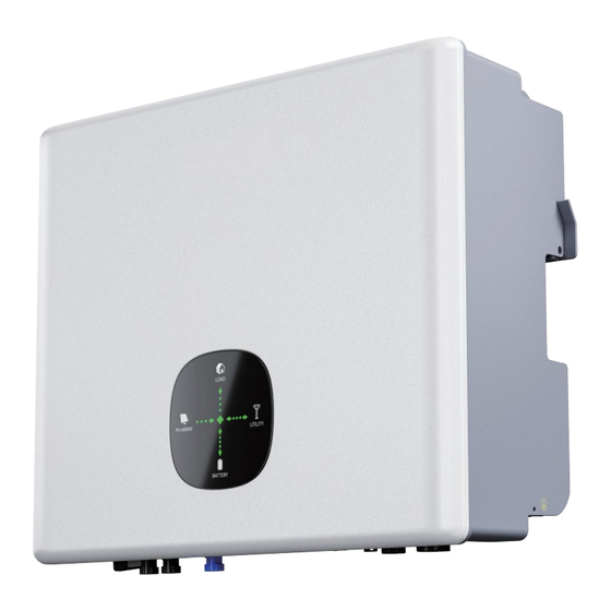
�. Introduction The inverter is called hybrid or bidirectional solar inverter and is suitable for solar systems with participation of PV, battery, loads and grid system for energy management. The energy generated by the photovoltaic system can be used to optimize the structure of household electricity consumption, the excess energy is used to charge the battery, and the remaining energy is exported to the grid. -
Page 6: Introduction To Operating Modes
�.� Introduction to operating modes Light Board Display : Light Board Display : Mode � Mode � According to different system configurations and layouts, the inverter can usually beset to the following When the grid is powered off, operating modes. The grid and photovoltaic system automatically... -
Page 7: Specifications Parameters
�.� Specifications parameters <�% THDI @Full load ��A AC inrush current Model H����H-EU H�����H-EU H�����H-EU MAX. output ��A PV Input data overcurrent protection AC maximum output ��A Max. recommended �����W �����W �����W fault current PV power AC Output(Off-grid) ����V Max. DC voltage ����W �����W �����W... -
Page 8: Installation Descriptions
� . Installation descriptions ���*���*���mm Dimensions(W/H/D) ��.�kg Weight �.� Example of wrong installation Class I Protective Class Wall mounted Installation Operating temperature -��~��℃ range Off-grid port Off-grid port Relative humidity �~���% (Non-condensing) power grid ≤����m Altitude load Free cooling The off-grid side cannot be connected in parallel. A single PV array cannot be connected Cooling If necessary, please contact after-sales. -
Page 9: System Wiring Diagram
�.� System Wiring Diagram System Wiring Diagram Note: According to Australian safety regulations, the neutral wires of the grid-connected side and the off-grid The energy storage inverter wiring system side must be connected together, otherwise the off-grid function cannot be used normally. Example of connecting N wires with PE wires in the distribution box Such as Australia, New Zealand, South Africa, etc. -
Page 10: Packing List
Model � � � � � Schematic representation of grid systems with no special requirements for electrical connections ��A, ≥���V ��A/���V ��A/���V, �L/N/PE ��mA RCD (Type A), H����H-EU main breaker Note: the off-grid ground wire and ground bar must be properly connected to work properly. DC breaker AC breaker ��mA RCD (Type A) -
Page 11: Installation
* The images shown here are for reference. The actual product and quantity are based on delivery. MC� PV Connection Crimping Pliers Heat Gun Multimeter Meter Wrench Communication Cable x� �.� Installation Allen Wrench Steel Tape Socket Wrench Set Vacuum Cleaner �.�.�... -
Page 12: Mounting Inverter
�.�.� Mounting inverter Rule �. Inverter should be installed vertically with a max rearward tilt of ��°. Rule �. Ambient temperature should be lower than ��°C.(Too high ambient temperature will de-rate the inverter's power efficiency). The product is heavy, please take it out of the package carefully. The inverter is only suitable for installation on non-combustible solid surfaces such as concrete. -
Page 13: Electrical Connections
�.�.� PV wiring connection �.� Electrical connections Before connecting PV panels/strings to the inverter, please make sure all requirements listed below are �.�.� Connect the PV input line followed. �. The total short-circuit current of a PV string must not exceed the inverter's max DC current. Connect the PE cable to the grounding plate at the grid side. -
Page 14: Connect The Battery Cable
· Check the cable connection of the PV string for polarity correctness and ensure that the opencircuit �.�.� Connect the battery cable voltage in any case does not exceed the inverter input limit of ���V. Be aware of electrical shock hazards or chemical hazards. If the battery does not have a built-in DC circuit breaker, please ensure that an external DC circuit breaker (≥��A) is connected. - Page 15 � � Notice: If the battery port is not used, install a dust cap to prevent rain and dust from entering the inverter. · Thread the cable through the cable gland and insert the crimp contact into the insulator. A clicking sound is heard to indicate that it has snapped into place.
-
Page 16: On-Grid & Off-Grid Connection
�.�.� On-grid & Off-grid connection �.�.�.� Off-grid connection When the inverter is connected to the grid, add an external AC circuit breaker to isolate the grid from The inverter has on-grid and off-grid function. The inverter will transmit power through the AC grid port the inverter if necessary. -
Page 17: On-Grid Connection
� Align the square opening on the grid terminal with the foot buckle on the inverter grid port and Notice: insert. If the off-grid port is not used, please install a dust plug for the AC load connector to prevent rain and The foot buckle entering the grid terminal and exposing the upper opening followed by a "click"... - Page 18 � Insert the cable conductor core into the terminal and crimp. Ensure that the cable sheath is not Notice: locked into the connector. · All electrical connections must be in accordance with local and national standards. · Only with the permission of the local utility grid company, the inverter can be connected to the utility Thread an appropriate length of AC cable through the waterproof terminal.
-
Page 19: Connect Smart Meter
Declarations for The Back-up Function �.�.� Connect smart meter The back-up output of the hybrid inverters has over load ability. And the inverter has self-protection derating Before connecting the smart meter, make sure the AC cable is completely isolated from the AC at high ambient temperature. - Page 20 Smart meter wiring diagram Item User interface Item User interface ��� means table address Description combined power A phase voltage=���.�V � �� Note: Please be sure to wire according to the above wiring rules, otherwise, the inverter will factor PFt=�.��� not operate normally.
-
Page 21: Connection Ground Fault Alarm
Note: When the smart meter is used with this product, the current ratio is set to ��, and the voltage ratio Item Color CAN(BMS) � � � � is set to �.�. � WAKE_UP � � � � range and white �... -
Page 22: Connect Wifi Module
�.�.� Logger status �.� Connect WIFI module Check Indicator light The WIFI communication function is only applicable to the WIFI module, please refer to the following figure to install the WiFi module Lights Implication Status Description(All lights are single green lights.) �.Light off: Connection to the router failed. -
Page 23: Abnormal State Processing
�.�.� Abnormal state processing �.� The connection mode of COM If the data on platform is abnormal when the stick logger is running, please check the table below and according to the status of indicator lights to complete a simple troubleshooting. If it still can not be resol-ved or indicator lights status do not show in the table below, please contact Customer Support. -
Page 24: Commissioning
�. Commissioning DRM ("AU"/"NZ") ·When the inverter is applied in Australia, the DRMS terminal needs to be connected. �.� Inspection before commissioning The following table lists the DRMs supported by the inverter. �.�.� Connection check PV Side Mode Requirement �. Before checking, make sure that the DC switch and the breaker of the combiner box on the AC side are disconnected. -
Page 25: Electrical Inspection
Class I Operation ambient temperature -25℃ -+60 ℃ Dongguan Hinen New Energy Technology Co.,Ltd S/N:H12000HEU012403C00001 Nameplate PV Side Open circuit voltage and polarity ·Turn the multimeter to the DC position, connect the red test lead (positive pole) to the positive pole of the string, and connect the black test lead (negative pole) to the negative pole of the string, and the displayed voltage is the current open circuit voltage. -
Page 26: Powering On The System
Checking Method for String Grounding ·In the picture on the right, the multimeter shows that the current battery voltage is ���V, the red test lead is connected to the positive pole, the black test lead is connected to the negative pole, and the positive and negative polarities are correct;... -
Page 27: Shutting Down The System
�. APP �.� Internet connection With the WIFI module installed, view corresponding information through SOLARMAN APP or SOLARMAN WEB. Battery on APP input boot command Operating status � �.� Shutting down the system Shutdown steps ·If maintenance or inspection is required, please follow the steps below to shut down the machine. �. -
Page 28: User Registration
Method � �.� Plant creation Scan the following QR code to download and install the App according to the prompt information. � After successful login, enter the main interface, please click the "Add Now" button to enter the add power plant interface. Please choose whether the installer is responsible for the post operation and maintenance of the power plant according to the actual situation. -
Page 29: Add A Logger
� As shown in the figure, you can enter the serial number of your logger in the serial number input box, or click on the scan code on the right side of the input box to add your logger by After determining the location of the power scanning the code. -
Page 30: Device Networking
�.� Device networking After Bluetooth is turned on and WIFI connection is successful, we will enter the following interface and enter the password to confirm that there are no errors in succession. Click "Start to configure" to enter the interface of configuring equipment detection. Please wait patiently. �... -
Page 31: Observe The Running Status Of The Device
�.� Observe the running status of the device After the power plant is built and the logger is successfully added, we can see the working status of the entire energy storage system in real time. In "Real Time", we can see the working situation of the energy storage system, the situation of ��... - Page 32 �.� View the system information and parameters System information and parameter introduction Enter to view the system information and parameters Name Description Shows the information on DC power generation, AC power � Electricity Generation � Click anywhere on this page to �...
- Page 33 Version Information Here is the system version information, includ- ing the system's software version, battery software version, and batter y hardware version. The system software version includes the monitoring software version, the software version identification and the safety regulation version. Electricity Generation The main information here is the genera- tion information of the system, including...
- Page 34 Temperature The main information here is the ambient tem- perature at which the system operates, the temperature of the inverter's heat sink, the temperature of the heat sink. Battery Here is the information about the batteries assigned to the system: current battery status, battery type, battery host voltage, battery slave voltage, battery power, battery charging power, battery discharging power, remaining battery...
- Page 35 If you want to know more detailed information, please refer to the user manual on the APP, as shown below: Here is the main batter y management system BMS related information, including BMS battery voltage, BMS battery current, BMS temperature, BMS maximum charging c u r r e n t , B M S m a x i m u m d i s c h a r g i n g current, BMS SOC and so on.
- Page 36 " can only be viewed but not changed. If you need to change them, please You can find the "Remote Power Control" function in the "Batch Commands", which is a setting to contact your installer or HINEN. control fast charging and discharging.
- Page 37 Period Time Number Time Periods There are �� priority periods in the APP, and each period has three setting options. After setting all the charging and discharging periods, we can set the “Number Time periods” to activate the set charging and discharging periods. ·...
- Page 38 Prioritization Mode Set ON/OFF Enable In the actual use of the inverter, it usually involves the setting of the priority level, and there are general- ly three priority setting methods: "Load Priority", "Battery Priority" and "Grid Priority". This is the device start switch. After plugging in the device, the device will enter standby mode and the device will Types Of Prioritization Models...
- Page 39 Anti-Reverse Current Function · Set back flow meter power limit: After the anti-reverse current function is In the single command, Anti-Reverse Current function is divided intosuch as "Read/Set Local turned on, and the input is from � to Anti-Backflow Enable", "Read/Set Backflow Meter Power Limit", and "Read/Set backflow Fault ���%, which is mainly to control the grid- connected power of the whole system.
- Page 40 Enter the number corresponding to the battery protocol and send the command. Battery Protocol Code Single-phase inverter Three-phase inverter � PYLON Protocol � HINEN Protocol � Growatt Protocol Growcol Protocol � SHOTO Protocol � GoodWE Protocol �...
- Page 41 The following settings with " " are only for users to view and cannot be changed. If you need to change the settings that require professional operation, please contact your installer or HINEN. First Order Protection In the first order protection parameters, the main...
- Page 42 Lead Acid Limit On Line Limit This setting is set for the battery used by the user. If the user uses a lead-acid battery, it is set according to the This setting is before the grid connection, when the relevant parameters of the battery. grid-connected voltage is within the range of low voltage and high voltage, and at the same time within ·...
- Page 43 PF Model Power Factor (applicable to specific countries, please refer to local grid requirements). Mode Comment Off FixedPFSetMode Power factor UserSetLinePFMode ConstQLeadPFMode Q_Percentage ConstQLagPFMode Q_Percentage Q(P)PFMode QP_p� Rate QU_PercentMax QU_Q�Percent 滚滚长江东逝水 QU_Q�Percent QU_PercentMin QU_UV_Stop Q(u)PFMode QU_UV_Start QU_OV_Start QU_OV_Stop Qu Delay Time Qu Lock in Power Qu Lock Out Power DefaultLine�RunPFMode...
- Page 44 Volt-watt Mode Comment PU_Enable PU_VL_Stop PU_VL_Start PU_VH_Start PU_VH_Stop Voltage active work PU_VLStopPower PU_VLStartPower PU_VHStartPower PU_VHStopPower PU_DelayTime �� ��...
- Page 45 Reactive power control, reactive power standard curve cos φ = f(P) Mode Comment Power Restart Slope EE Power Restart Slope EE (�-����%/min) φ Active Power Rate Slope EE Active Power Rate Slope EE (�-����%/min) Active Power Percent Active Power Percent (�-���%) �.�...
- Page 46 Single Command Anti-islanding Enable Power Control Power control Power control, divided into Active P Rate and Reactive P Rate, selectable The inverter uses the active frequency drift (AFD) method, also known as frequency biasing, to range is �%-���%. prevent the islanding effect. Active P Rate refers to the output active power, The anti-islanding enable is on by default, so please select it carefully in order to protect equip- which is the electric power needed to maintain...
- Page 47 AC Charge Enable OFDerat Curve Enable When AC Charging is enabled, it will allow the grid to charge the batteries. This is "Over frequency load reduction Enable" setting. When it is enabled, the active power of the grid begins to decrease when the frequency reaches a certain value.
- Page 48 New Zealand Notice: �. For compliance with AS/NZS ����.�:���� please select from Australia A/B/C. Please contact your local electricity grid operator for which region to select. �. For changes to default settings please contact the installer or HINEN. �� ��...
- Page 49 �.� Trouble codes �.�.� Fault reference code � Click "Send Command" to complete the setup. Main Fault Code Inverter State Fault Discription Suggestion �. After shutdown,Check the temperature, normal restart the inverter. Error ��� Error/Off NTC Temperature too high �. If the error message still exists, contact manufacturer.
- Page 50 �.�.� Warning reference code Main Fault Code Inverter State Fault Discription Suggestion Main Warning Code Inverter State Warning Discription Suggestion �. Restart inverter. �. Check if the meter is reversed or not. �. If error message still exists,contact manu- Error ��� Error/Off...
- Page 51 Main Warning Code Inverter State Warning Discription Suggestion Main Warning Code Inverter State Warning Discription Suggestion �. After shutdown,Check the dry Dryconnect �. Check battery voltage Dryconnect function Warning ���� Warning/Off Battery voltage low wiring. �. If error message still exists,contact Warning ����...
- Page 52 Operational problems Q & A About SOLARMAN Smart Operation and Monitoring Operational problems Solution �. Why can't I find a Solar-WiFi* signal on my mobile device? Normally, the inverter can search for Solar-WiFi* signal after it is powered on. But when the inverter is connected to the internet, the Solar-WiFi signal disappears.
- Page 53 About Smart Meter Functions About battery operation �. How to enable the output anti-reverse current function? �. Why does the battery not discharge when the grid is not available, but it can discharge normally For the inverter system, this function can be realized in the following ways: when the grid is available? (�) Make sure the smart meter connection and communication are good.
- Page 54 �. Other �.� Fault details When a fault occurs, the following error information can be viewed through SOLARMAN Smart. Reason Error message Solution Explanation Grid power is unavailable �. Use a multimeter to check whether there is voltage on the AC side, and ensure that the power grid is available. Utility loss (power failure or grid �.
- Page 55 Environmental Class Definition �.� Hazard avoidance quick checklist � . Do not install the inverter near flammable, explosive or strong electromagnetic equipment. Environmental Relative humidity External temperature Apply to conditions �. T he inverter is heavy, be careful when taking it out of the bag. �.B e fore connecting the battery to the inverter, ensure that the battery circuit breaker is disconnected, and the Outdoor -��~��...
- Page 56 �.�.� Daily maintenance �. Before maintenance, please use a multimeter and other instruments to detect the voltage between the metal parts that need to be touched or may be touched and the grounding copper bar to avoid electric shock. �. During maintenance, please pay attention to the warning labels of the inverter to prevent personal injury caused by high voltage.
Need help?
Do you have a question about the H8000H-EU and is the answer not in the manual?
Questions and answers