Table of Contents
Advertisement
Quick Links
Advertisement
Table of Contents

Related Manuals for Hinen H3600-OG


Summary of Contents for Hinen H3600-OG
- Page 1 SINGLE-PHASE OFF-GRID INVERTER H����-OG / H����-OG/ H����-OG/ H����-OG Dongguan Hinen New Energy Technology Co., Ltd Add: No.�� Dongkang Road, Dalingshan Town, Dongguan City, Guangdong Province, China User Manual Tel: +�� (���) ���� ���� Email: market@hinen.com Website: https://www.hinen.com...
-
Page 2: Safety And Warnings
Disclaimer Safety and Warnings OFF-GRID inverters need to be transported, used and operated under suitable environmental and The �K off-grid series strictly abide by the relevant safety regulations for product design and testing. During electrical conditions. In the following cases, the manufacturer reserves the right not to provide installation, operation or maintenance, please carefully read and follow all instructions and precautions in the after-sales service or assistance: inverter or user manual, any improper operation may cause personal or property damage. - Page 3 �.� Preparation � �.� Mounting the Unit � WARNING: Please read and retain this manual for future reference. �.� Battery Connection �� �.�.� Lead-acid Battery Connection �� Please be clear which kind of battery system you want, lithium battery system or lead-acid battery �.
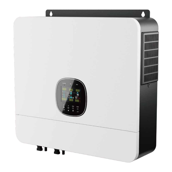
- Page 4 �.� Product Overview � � � Home Solar Panel Loads � Grid � Generator � � � �� �� Battery �� Hybrid Power System This is a multifunctional off-grid solar inverter, integrated with a MPPT solar charge controller, a high frequency pure sine wave inverter and a UPS function module in one machine, which is perfect for off-grid backup power and ��...
- Page 5 �.� Specifications Parameters Inverter Mode Specifications Rated Output Power ����VA/����W ����VA/����W ����VA/����W ����VA/����W H����-OG H����-OG H����-OG H����-OG Max. AC Output ����W ����W ����W ����W Active Power Line Mode Specifications Parallel Capability Yes,�� units maximum Input Voltage Waveform Sinusoidal (utility or generator) Output Voltage Waveform Pure Sine Wave Nominal Input Voltage...
-
Page 6: General Specifications
Low DC Warning Return Max. Inverter Back Feed Low DC Cut-off SOC +��% �A SOC (Li Mode) Current To The Array Low DC Cut-off SOC Default ��%, �%~��% settable Max. PV Charging Current ��A ���A ���A ���A (Li Mode) Max. Charging Current High DC Recovery Voltage ��.�Vdc (C.V. -
Page 7: Quick Installation
�.� Installation Tools �.� Unpacking and Inspection Protection Goggle Anti-noise Earplugs Dust Mask Safety Gloves Inverter Current sharing cable Parallel communication PV positive connector cable x� x� x� x� Safety Shoes Utility Knife Marker Pen Anti-static Bracelet PV Negative Connector Tubular terminal R-type terminal O-type terminal... - Page 8 �.� Preparation Before connecting all wiring, please take off bottom cover by removing four screws as shown below. 340mm Expansion Screw x� �.� Mounting the Unit Tighten the � expansion screws to install the unit. Consider the following points before selecting where to install: Do not mount the inverter on flammable construction materials.
- Page 9 �.� Battery Connection Please follow below steps to implement battery connection: �. Assemble battery ring terminal based on recommended battery cable and terminal size. �. Connect all battery packs as units requires. It’ s suggested to connect at least ���Ah capacity battery for �.�.�...
- Page 10 �.�.� Lithium Battery Connection �. The other end of RJ�� insert to battery communication port ( COM.INV ). If choosing lithium battery for the �K off-grid inverter, you are allowed to use the lithium battery only which we have configured. There're two connectors on the lithium battery, RJ�� port of BMS and power cable. Please follow below steps to implement lithium battery connection: �.
-
Page 11: Pin Number
AGM (default) RS��� port Pin number BMS port (for expansion) Lithium (only suitable when communicated with BMS) � WAKE.UP GND-S � GND-S EXT-CT_N 05 Battery type � GND-S RS���+ User-Defined � BAT.CANH+ GND-S � BAT.CANL- RS���- � GND-S CT_ON+ If “User-Defined” is selected, battery charge voltage �... - Page 12 �.� Communicating with Battery BMS in Parallel System If need to use communicate with BMS in a parallel system, you should make sure to connect the BMS communication cable between the battery and one inverter of the parallel system. It’ s recommended to connect to the master inverter of the parallel system. ��...
- Page 13 �.� AC Input / GEN / Output Connection CAUTION: Before connecting to AC input power source, please install a separate AC breaker between inverter and AC input power source. This will ensure the inverter can be securely disconnected during maintenance and fully protected from over current of AC input.
- Page 14 Last, insert AC output wires according to polarities indicated on terminal block and tighten terminal Make sure the wires are securely connected. screws. CAUTION: Important L→LINE (brown or black) Be sure to connect AC wires with correct polarity. If L and N wires are connected N→Neutral (blue) reversely, it may cause utility short-circuited when these inverters are worked in parallel operation.
- Page 15 �.�.� PV Module Selection �.�� Final Assembly After connecting all wiring, please put bottom cover back by screwing two screws as shown below. When selecting proper PV modules, please be sure to consider below parameters: �. Open circuit Voltage (Voc) of PV modules not exceeds max. PV array open circuit voltage of inverter. �.
-
Page 16: Function Buttons
Function Buttons �.� Power ON/OFF Button Description To exit setting mode To go to previous selection DOWN To go to next selection ENTER To confirm the selection in setting mode or enter setting mode �.� LCD Display Icons Once the unit has been properly installed and the batteries are connected well, simply press On/Off switch(located on the button of the case) to turn on the unit. - Page 17 Load lnformation In battery mode, battery icon will present Battery Capacity. Load icon. Load Percentage Battery Voltage LCD Display < �.���V/cell Displays load active power, apparent power, and load rate. �.���V/cell ~ �.�V/cell Indicate overload happened. Load >��% �.� ~ �.���V/cell Indicate short circuit happened.
-
Page 18: Program Description
Description Program Setting Option Program Description Setting Option SBU priority Maximum charging current: set total charging current for �� solar and utility chargers. If program item �� is set to enable, and the solar energy Default ���A, �A~���A Settable is greater than the limit set in program ��, the solar (Max. - Page 19 If “User-Defined” is selected, battery charge voltage and low DC cut-off voltage can be set up in program ��, ��and ��. AC Charging Maximum PYLON HINEN �� Default ��.�A,��.�V~���.�V Settable. Current. Note: If the set value in program �� is less than the set value in program ��, the value set in program ��...
- Page 20 Program Description Setting Option Program Description Setting Option �� Floating charging voltage. Active percentage setting. �%~���% If self-defined is selected �� in program ��, this program Default ��.�V, ��.�V~��.�V Settable. can be set up. Battery equalization enable. Battery equalization disable (default).
-
Page 21: Setting Information
�.� Display Information Program Description Setting Option The LCD display information will be switched in turns by pressing “UP” or “DOWN” key. The selectable information is switched as below order: voltage, frequency, current, power, firmware Clear power version. generation. �� Restore factory settings. - Page 22 ➀ Grid frequency Operation mode Description LCD display (Or diesel generator frequency) ➁ Off-grid frequency ➂ Load factor ➃ PV� current Fault Mode ➄ Battery current Note: The red fault light is ➅ System failure *Fault mode: Errors are always on, and the caused by inside circuit alarm buzzer sounds.
- Page 23 �.� Wiring Connection The cable size of each inverter is shown as below O-type terminal: �.� Introduction Recommended battery cable and terminal size for each inverter: This inverter can be used in parallel with two different operation modes. �. Parallel operation in single phase with up to � units. Model Wire Size Torque value...
- Page 24 Recommended breaker specification of AC input with single phase: �.� Parallel Operation in Single Phase Model � units � units � units � units � units WARNING: All inverters must be connected to the same batteries and ensure each ���A/���VAC ���A/���VAC ���A/���VAC ���A/���VAC...
- Page 25 Three inverters in parallel: Four inverters in parallel: Power Connection Power Connection Battery Grid Battery Load Grid Load Communication Connection Communication Connection � � � � � � � �� ��...
- Page 26 Six inverters in parallel: Five inverters in parallel: Power Connection Power Connection Battery Battery Grid Grid Load Load Communication Connection Communication Connection � � � � � � � � � � � �� ��...
- Page 27 Two inverters in one phase and only one inverter for the remaining phases: �.� Parallel Operation in Three Phase Power Connection WARNING: All inverters must be connected to the same batteries and ensure P� P� P� each group of cables from the inverters to the batteries in the same length. One inverter in each phase: Power Connection Battery...
-
Page 28: Power Connection
Two inverters in two phases and only one inverter for the remaining phase: Three inverters in one phase and only one inverter for the remaining two phases: Power Connection Power Connection P� P� P� P� P� P� Battery L� Grid L�... - Page 29 Four inverters in one phase and one inverter for the other two phases: Communication Connection Power Connection P� P� P� P� P� P� � � � � � � Battery Three inverters in one phase, two inverters in second phase and one inverter for the third phase: Power Connection L�...
- Page 30 �.� PV Connection Step � Switch on all AC breakers of Line wires in AC input. It’ s better to have all inverters connect to utility at the same time. If not, it will display warning ��. Please refer to user manual of single unit for PV Connection on Page ��. LCD display in Master unit LCD display in Slave unit CAUTION:...
-
Page 31: Fault Event
Step � Switch on all AC breakers of Line wires in AC input. If AC connection is detected and three phases are matched with unit setting, they will work normally. Otherwise, they will display warning ��/�� and will not work in the line mode. Fault Code Fault Event Icon Display... - Page 32 Fault Code Fault Event Icon Display �� AC input overcurrent Warning Warning Event Audible Alarm Icon Flashing PV current sample fault Code �� �� Fan is locked when inverter is on Beep thrice every seconds �� Inverter CurrOverFault �� Over temperature Beep once every second ��...
- Page 33 Equalization function is added into charge controller. It reverses the buildup of negative chemical effects like stratification, a condition where acid concentration is greater at the bottom of the battery than at the top. Problem LCD/LED/Buzzer Explanation What to do Equalizationalso helps to remove sulfate crystals that might have built up on the plates.
- Page 34 Problem LCD/LED/Buzzer Explanation What to do Restart the machine and if the error Please use the optional WIFI module to connect it to the USB port of the �KW off-grid inverter to monitor the Inverter power-up zero Fault code �� occurs again, return to the repair center.
Need help?
Do you have a question about the H3600-OG and is the answer not in the manual?
Questions and answers