Advertisement
Quick Links
SINGLE-PHASE
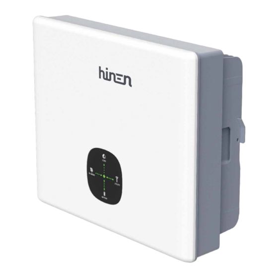
HYBRID INVERTER
H����-EU / H����-EU / H����-EU / H����-EU / H����-EU / H����-EU
Dongguan Hinen New Energy Technology Co., Ltd
Add: No.�� Dongkang Road, Dalingshan Town,
Dongguang City, Guangdong, China
Quick Installation Guide
Tel: +�� (���) �������� ext ����
Email: service@hinen.com
Website: https://www.hinen.com
Hinen Australia Pty. Ltd.
Add: Suite ���,Level �, Tenancy �,��� Mount Street, North Sydney
Email: service@hinen.com.au
Tel: +�� � ���� ����
Website: https://au.hinen.com
Advertisement

Summary of Contents for Hinen H3000-EU
- Page 1 SINGLE-PHASE HYBRID INVERTER H����-EU / H����-EU / H����-EU / H����-EU / H����-EU / H����-EU Dongguan Hinen New Energy Technology Co., Ltd Add: No.�� Dongkang Road, Dalingshan Town, Dongguang City, Guangdong, China Quick Installation Guide Tel: +�� (���) �������� ext ����...
- Page 2 �. Packing List Wall mountings are placed horizontally on the Use impact drill to drill holes of �mm in diameter and installation wall, and making marking points with a ��mm in depth according to the marking points. marker. Upon receiving the hybrid inverter, please check if any of the components as shown below are missing or broken.
-
Page 3: System Connection Diagrams
System Connection Diagrams Note: According to Australian safety requirements, the neutral cables of the on-grid side and backup side must be connected together. Otherwise, the backup function would not This diagram is an example for an application that neutral connects with the PE in a work. - Page 4 This diagram is an example for grid systems without special requirements on electrical wiring This diagram is an example for grid systems without special requirements on electrical wiring connection (with smart meter) . connection (with CT) . Note: The back-up PE line and earthing bar must be grounded properly and effectively. Note: The back-up PE line and earthing bar must be grounded properly and effectively.
- Page 5 �. Electrical Connection Step � Grounding Protection Wire M� �.� N · m Step � Grid 7-8mm 20-25mm S≈�mm² 13mm≤ ≤18mm 2 N·m � �...
- Page 6 · After the AC Grid is installed, a protective cover must be added. Remove the Grid plug 0.2~0.3 N·m Remove the EPS plug Warning: Disconnect power from grid and equipment, and remove grid terminals by professional installer. The Inverter Side Step �...
- Page 7 Step � Battery Keep the PV switch in the OFF position. � Make sure the cable polarity is correct. Step � COM Connection Mode � COM/DRM� � REFGEN Remove the PV plugs � DRM�/� � DRM�/� � DRM�/� � DRM�/� �...
- Page 8 �. Route the signal cable through the terminal protection cover, as shown in the figure. �. Insert the signal cable into the wiring hole and tighten it with Phillips screwdriver. �. Install and lock the parts of the connector according to the figure. Internal wiring diagram of COM connector: The METER port connects to a smart The CAN port connects to the BMS...


Need help?
Do you have a question about the H3000-EU and is the answer not in the manual?
Questions and answers