
Related Manuals for Future Design P41


Summary of Contents for Future Design P41
- Page 1 User's Manual P41 / P91 P41 / P91 Auto-Tune Fuzzy / PID Auto-Tune Fuzzy / PID RoHS Profiling Controller Profiling Controller LISTED...
- Page 2 Information in this user's manual is subject to change without notice. Copyright January 2009, Future Design Controls, all rights reserved. No part of this publication may be reproduced, transmitted, transcribed or stored in a retrieval system, or translated into any language in any form by any means without the written permission of Future Design Controls.
-
Page 3: Table Of Contents
Contents Page No Page No Chapter 1 Overview ----------- 5 Chapter 1 Overview ----------- 5 Chapter 4 Profiler Operation -- 63 Chapter 4 Profiler Operation -- 63 1-1 General ------------------------- 5 4-1 What is a Setpoint Profiler ----- 1-2 Ordering Code ---------------- 9 4-2 Segment Connections -------- 1-3 Programming Port ---- ------ 11 4-3 Profiler Modes --------------------... - Page 4 Figure 2.1 Mounting Dimensions -------------------------------------------------------------------------------------- 33 Figure 2.2 Lead Termination for P41---------------------------------------------------------------------------------- 34 Figure 2.3 Lead Termination for P91---------------------------------------------------------------------------------- 34 Figure 2.4 Rear Terminal Connection for P41 ----------------------------------------------------------------------35 Figure 2.5 Rear Terminal Connection for P91 ---------------------------------------------------------------------- 35 Figure 2.6 Power Supply Connections ------------------------------------------------------------------------------- 36 Figure 2.7 Sensor Input Wiring ----------------------------------------------------------------------------------------- 36...
-
Page 5: Chapter 1 Overview
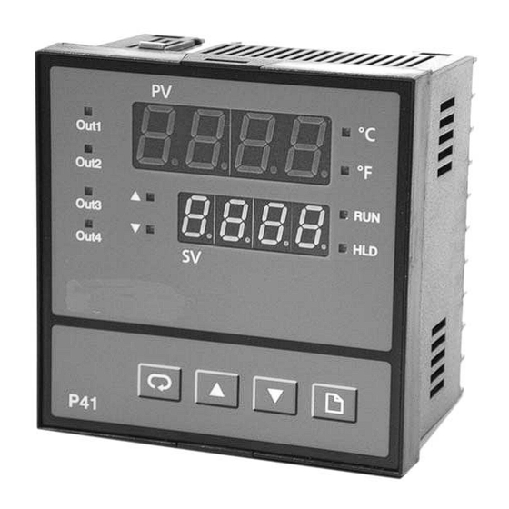
The P91 is a 1/16 DIN size panel mount profiling controller. It can also be used for rail mount by adding a rail mount kit. The P41 is a 1/4 DIN size panel mount profiling controller. - Page 6 PID control with properly tuned PID + Fuzzy control Temperature point Figure 1.1 Figure 1.1 Fuzzy Control Fuzzy Control Advantage Advantage Load Disturbance Warm Up Time The “P” series can be configured as a single set point controller (static mode) or a ramp and dwell profiling controller (profile mode). The profile mode feature allows the user to program up to 9 profiles of up to 64 free-format (ramp, dwell, jump or end) segments each.
- Page 7 Analog Retransmission Analog Retransmission Output 5 and output 4 (P41 only) of the products can be equipped with an analog output module. The output can be configured for transmitting the process value as well as set point value.
- Page 8 Auto-tune The auto-tune function allows the user to simplify initial setup for a new system. The internal algorithm is provided to obtain an optimal set of control parameters for the process which can be applied when the process is warming up (cold start) or after the process has been operating at steady state (warm start) conditions.
-
Page 9: Ordering Code
9: Special Order 9: Special Order D: RS-485 interface Isolated D: RS-485 interface Isolated E: RS-232 interface Isolated E: RS-232 interface Isolated Output 4 (P41 ONLY) Output 4 (P41 ONLY) Output 1 Output 1 0: None 0: None 0: None... - Page 10 CC91-1 = Programming Port Cable RK91-1 = Rail Mount kit for P91 DC21-1 = 20V/25mA DC Output Power Supply for P41 Output 5 Isolated DC21-2 = 12V/40mA DC Output Power Supply for P41 Output 5 Isolated DC21-3 = 5V/80mA DC Output Power Supply for P41 Output 5Isolated...
-
Page 11: Programming Port
1-3 Programming Port 1-3 Programming Port Rear Front Panel Terminal Figure 1.2 Figure 1.2 Programming Port Programming Port Overview Overview Access Hole Access Hole A special connector (CC91-1) is used to connect the programming port to a PC for automatic configuration. The PC must have FDC-Set installed to use the configuration feature via PC. -
Page 12: Keys And Displays
1- 4 Keys and Displays 1- 4 Keys and Displays KEYPAD OPERATION KEYPAD OPERATION SCROLL KEY : SCROLL KEY : This key is used to select a parameter to be viewed or adjusted. UP KEY : UP KEY : This key is used to increase the value of selected parameter. DOWN KEY : DOWN KEY : This key is used to decrease the value of selected parameter. - Page 13 Upper Display, to display process value, menu symbol and error code etc. Output Status indicators for Lower Display, to display set point value, output1~output 4 parameter value or control output value etc. On : profile running Flashing: profile in delayed state Out1 LF LF Out2...
- Page 14 The unit will display the program code for 2.5 seconds during power up. The code is the program number followed by the version number. For the P41, the program number is 37. The program number for the P91 is 38. In the example figure below, the version number is 12.
-
Page 15: Key Operation Flowchart
1-5 Key Operation Flowchart 1-5 Key Operation Flowchart Mode Page Mode Page Profile Page Profile Page Home Page Home Page Home Home Display Display ( 1-9 ) (MODE) (Profile run mode) (Profile hold mode) (Static mode) (Automatic tuning PID1 mode) TIME (Automatic tuning PID2 mode) (Manual mode) - Page 16 High High Calibration Calibration Calibration Calibration Configuration Configuration Page Page Page Page Page Page 5 sec. 5 sec. (CALO) (CAHI) INPT UNIT (OFSTL) (OFSTH) INLO Using key to Using key to INHI adjust the offset low value adjust the offset high value FILT EIFN (lower display) until the...
-
Page 17: Parameter Descriptions
1-6 Parameter Descriptions 1-6 Parameter Descriptions Register Parameter Default Data Parameter Description Range Address Notation Value type Controller (Static mode) 25.0 C Set point value Low: SPLO High: SPHI (77.0 F) See Note *1 Low: 1.00 High: 9.63 Indicate the current PFSG Profile/Segment 1.00... - Page 18 Parameter Register Parameter Default Data Range Description Address Notation Value type : 4 - 20 mA linear current input : 0 - 20 mA linear Input sensor current input selection : 0 - 60 mV linear millivolt input INPT : 0 - 1V linear NOTE: voltage input Linear Inputs...
- Page 19 Parameter Register Parameter Default Data Range Description Address Notation Value type 0 second time constant 0.2 second time constant 0.5 second time constant 1 second time constant 2 seconds time constant FILT Filter damping 5 seconds time time constant constant of PV 10 seconds time constant...
- Page 20 Parameter Register Parameter Default Data Range Description Address Notation Value type Select BPLS ( bumpless transfer ) or 0.0 ~ 100.0 % to O1FT continue output 1 control Output 1 failure function as the unit fails, or transfer status select OFF (0) or ON (1) for ON-OFF control.
- Page 21 : No function : Alarm 3 output : Reverse alarm 3 output OUT4 : Event 3 output Output 4 function (for P41 only) : Retransmit process value : Retransmit set point value : DC power supply output UMP4191A-July-2024...
- Page 22 Value type : Output 4 OFF Output 4 failure O4FT as unit fails transfer status : Output 4 ON (for P41 only) as unit fails Low limit value for Low: 0 High: 100.0 % OP4L output 4 (for P41 only)
- Page 23 Parameter Register Parameter Default Data Range Description Address Notation Value type 2.4 Kbits/s baud rate 4.8 Kbits/s baud rate 9.6 Kbits/s baud rate BAUD Baud rate of digital communication 14.4 Kbits/s baud rate 19.2 Kbits/s baud rate 28.8 Kbits/s baud rate 38.4 Kbits/s baud rate : Even parity PARI...
- Page 24 : Deviation high alarm : Deviation low alarm ALF3 ALF3 Alarm 3 function : Deviation band (for P41 only) high/low alarm : End of profile alarm : Hold mode alarm : Static mode alarm : Normal alarm action : Latching alarm action...
- Page 25 Hysteresis control 0.1 C A3HY High: 50.0 C for alarm 3 Low: 0.1 (90.0 F) (0.2 F) (for P41 only) Reserved : No parameter selected : INPT selected for home page : UNIT selected for home page : DP selected for...
- Page 26 Parameter Register Parameter Default Data Range Description Address Notation Value type Select 4'th SEL4 parameter Same as SEL1 for home page Select 5'th SEL5 parameter Same as SEL1 for home page Select 6'th SEL6 parameter Same as SEL1 for home page Select 7'th SEL7 parameter...
- Page 27 Parameter Register Parameter Default Data Range Description Address Notation Value type : Continue profile from the last setpoint value : Continue Profile Power fail from current PV recovery : Static mode, SP1 : OFF mode Low : 0.00 High : 99.59 Holdback wait 1.00 (hour.minute)
- Page 28 Parameter Register Parameter Default Data Range Description Address Notation Value type Time duration or RTRR Ramp rate for Low: 0 High: 5999 ramp segment Four-bit binary number ( 0=inactive 1=active ) States assignment of PID selection P2EV and event outputs Event 1 for ramp, and Event 2...
- Page 29 Parameter Register Parameter Default Data Range Description Address Notation Value type RTD calibration Low: -1999 high: 1999 RTDL low coefficient RTD calibration Low: -1999 high: 1999 RTDH high coefficient Cold junction calibration low CJLO Low: -5.00 high: 40.00 coefficient Cold junction calibration high CJHI Low: -1999...
- Page 30 Parameter Register Parameter Default Data Range Description Address Notation Value type Reserved Reserved Reserved Reserved Reserved Low: -32768 High: 32767 Process value Set point value for Low: SPLO High: SPHI control Output 1 percentage Low: 0.00 High: 100.00 value (Heating ) Output 2 percentage Low: 0.00...
- Page 31 Parameter Register Parameter Default Data Range Description Address Notation Value type Set point for Low:SPLO High: SPHI SPSG current segment Time remaining for the current Low:00.00 High: 99.59 TIME segment Cycle remaining Low:1 High: 9999 for the current 139** CYCL 10000=infinite loop Program and...
-
Page 32: Chapter 2 Installation
Chapter 2 Installation Chapter 2 Installation Dangerous voltages capable of causing serious injury or death Dangerous voltages capable of causing serious injury or death may be present in this instrument. Before installation or prior to may be present in this instrument. Before installation or prior to beginning any cleaning or troubleshooting procedures, turn off power beginning any cleaning or troubleshooting procedures, turn off power to all equipment and follow proper lockout-tagout procedures. - Page 33 Figure 2.1 Mounting Dimensions Figure 2.1 Mounting Dimensions Panel Cutout Panel 3.62” 92 mm 53 mm 2.08” 1.77” Panel 45 mm Panel Cutout 11.5mm 104.8mm .45” 4.13” Panel Mount Panel Mount 7.5mm 2.44” 62.0mm 48.0mm 1.89” 104.8mm 11.5mm 4.13” .45” 6.5mm Optional .25”...
-
Page 34: Wiring Precautions
18 AWG. copper conductors with a maximum of 18 AWG. 7.0mm max. 3.2mm min. Figure 2.2 Lead Termination for P41 Figure 2.2 Lead Termination for P41 6.0mm max. Figure 2.3 Lead Termination for P91 Figure 2.3 Lead Termination for P91... - Page 35 PTB, mA+ TC-, V- TC-, V- CAT. I I PTB, mA- PTB, mA- V mA RTD Figure 2.4 Rear Terminal Connection for P41 Figure 2.4 Rear Terminal Connection for P41 Op5: RS-232: RXD COM RS-485: TX1 TX2 CAT. I I...
-
Page 36: Power Wiring
A 400 ohm K type or a 500 ohm J type thermocouple lead resistance will produce 1degree C error. For two-wire RTD inputs, terminals 19 and 20 on the P41, or terminals 5 and 6 on the P91 must be connected together. Three-wire RTD’s offer inherent lead resistance compensation provided that the three leads are of same gauge and equal length. -
Page 37: Control Output Wiring
2-6 Control Output Wiring 2-6 Control Output Wiring Fuse 120V/240VAC 120V/240VAC Mains Supply Mains Supply LOAD Figure 2.8 Output 1 Relay or Triac (SSR) to Drive Load Figure 2.8 Output 1 Relay or Triac (SSR) to Drive Load Fuse 120V /240V 120V /240V Mains Supply Mains Supply... - Page 38 Fuse 120V/240VAC 120V/240VAC Mains Supply Mains Supply LOAD Figure 2.12 Output 2 Relay or Triac (SSR) to Drive Load Figure 2.12 Output 2 Relay or Triac (SSR) to Drive Load Fuse 120V /240V 120V /240V Mains Supply Mains Supply Load Internal Circuit Internal Circuit 30mA / 5V...
-
Page 39: Alarm /Event Output Wiring
Figure 2.16 Alarm/Event Output Wiring Figure 2.16 Alarm/Event Output Wiring Note: Form C relay contacts are provided for alarm/event 2 (out3) on the P41 only. Alarm/event 3 (out4) is not available on the P91. 2-8 Event Input Wiring 2-8 Event Input Wiring... -
Page 40: Data Communication
2-10 Data Communication 2-10 Data Communication RS-485 to RS-232 RS-485 to RS-232 network adaptor network adaptor SNA10A RS-232 Twisted-Pair Wire Twisted-Pair Wire Max. 255 units can be linked Max. 255 units can be linked Terminator Terminator 220 ohms / 0.5W 220 ohms / 0.5W Figure 2.19 RS-485 Wiring Figure 2.19 RS-485 Wiring... - Page 41 9-pin 9-pin RS-232 RS-232 port port CC94-1 Figure 2.20 RS-232 Wiring Figure 2.20 RS-232 Wiring NOTE: If you use a conventional 9-pin RS-232 cable instead NOTE: If you use a conventional 9-pin RS-232 cable instead of CC94-1, the cable must be modified according of CC94-1, the cable must be modified according to the following circuit diagram.
-
Page 42: Chapter 3 Configuration
Chapter 3 Configuration Chapter 3 Configuration The parameters stored in Home page can be obtained by pressing the scroll key . The parameters in the Configuration page are obtained by pressing the page key 2 times to show the Profile page, then press and hold the page key for 5 seconds to enter the Configuration page. -
Page 43: Event Input
How to use INLO and INHI : How to use INLO and INHI : If 4 - 20 mA is selected for INPT, let SL specifies the input signal low (i.e. 4 mA), SH specifies the input signal high (i.e. 20 mA), S specifies the current input signal value, the conversion curve of the process value is then as follows : process value... -
Page 44: Control Outputs
3-4 Control Outputs 3-4 Control Outputs There are five control mode types that can be configured for the P series as shown in Table 3.2. Control OUT1 OUT2 O1HY A1HY Modes Heat only Cool only Heat: ON-OFF Cool: ON-OFF Heat: PID Cool: ON-OFF Heat: PID Cool: PID... - Page 45 Dead band = O1HY (SP1 O1HY) Time Output 1 Action Time Figure 3.2 Heat Only ON-OFF Control Figure 3.2 Heat Only ON-OFF Control Select for OUT1 and Heat only P (or PD) control: set TI1 and TI2 to ZERO. OFST is then used to adjust the control offset (manual reset) and O1HY is hidden.
- Page 46 Heat only PID control: Set for OUT1 and non-zero values for the proportional band and integral time. Perform an auto tune to obtain the proper tuning parameter values or set appropriate values for PB1, TI1 and TD1. If the control result is still unsatisfactory, it may be necessary to perform manual tuning to improve the control.
- Page 47 Output Power (%) PB1 or PB2 Case 2 Case 2 Output 2 Output 1 100% Output 1 Output 2 Process value positive Output Power (%) PB1 or PB2 Case 3 Case 3 Output 2 Output 1 100% Output 1 Output 2 Process value DB=0 Output...
- Page 48 CPB Configuration: The cooling proportional band is measured in % of The proportional band (PB) with a range 50-300. Set CPB to 100% to begin and examine the cooling effect. If cooling action should be enhanced then decrease CPB. If cooling action is too strong then increase CPB.
-
Page 49: Alarms
3-5 Alarms 3-5 Alarms The unit can be configured with up to three alarm outputs on the P41 at OUT2, OUT3 and OUT4 and up to two alarm outputs on the P91 at OUT2 and OUT3. There are 8 alarm functions and 4 alarm modes available for each alarm output. - Page 50 : A deviation high alarm is dependant upon the control set point and alerts the operator when the process deviates too high over the set point value. When the process is higher than SV+ASP1 (NOTE: ASP1 must be entered as a positive value), a deviation high alarm occurs. When the process falls below SV+ASP1-A1HY, the alarm is off.
- Page 51 : A deviation band high/low alarm presets two trigger levels relative to the control set point value. The two trigger levels are SV+ASP1 and SV-ASP1 for the high and low alarm values. When the process is higher than SV+ASP1 or lower than SV-ASP1, a deviation band alarm occurs.
- Page 52 The alarm modes (A1MD, A2MD and A3MD) are set by using a three bit binary number. alarm mode Description value A direct acting normal alarm output is off as the non-alarm condition and on as an alarm condition. The output state is inverted as a reverse alarm output is selected for OUT2, OUT3 or OUT4.
-
Page 53: Configure Home Page
3-6 Configure Home Page 3-6 Configure Home Page Conventional controllers are designed with fixed parameter scrolling. The “P” Series has the flexibility for you to select the parameters which are most useful to you and put these parameters in the home page. Hence, you can have a custom home page. - Page 54 Send the low signal to the input of unit, then press the key. If the process value (the upper display) is different from the input signal, you can then use the keys to change the OFSTL value (the lower display) until the process value is equal to the correct value you input to the unit.
-
Page 55: Digital Filter
3- 8 Digital Filter 3- 8 Digital Filter In certain application the process value is too unstable to be read. To improve this, a programmable low pass filter incorporated in the controller can be used. This is a first order filter with a time constant specified by the FILT FILT parameter. -
Page 56: Failure Transfer
3 -9 Failure Transfer 3 -9 Failure Transfer The controller will enter failure mode if one of the following conditions occurs: SBER occurs due to the input sensor break or input current below 1mA if 4-20 mA is selected or input voltage below 0.25V if 1-5 V is selected . -
Page 57: Auto-Tuning
3 -10 Auto-tuning 3 -10 Auto-tuning The auto-tuning process is performed at set point. The process The auto-tuning process is performed at set point. The process will oscillate around the set point during tuning process. Set the will oscillate around the set point during tuning process. Set the set point to a lower value if overshooting beyond the normal set point to a lower value if overshooting beyond the normal process value is likely to cause damage to the system. -
Page 58: Manual Tuning
Auto-Tuning Error Auto-Tuning Error If auto-tuning fails an ATER message will appear on the upper display If auto-tuning fails an ATER message will appear on the upper display in cases of : in cases of : If PB exceeds 9000 ( 9000 PU, 900.0 F or 500.0 C ). If PB exceeds 9000 ( 9000 PU, 900.0 F or 500.0 C ). - Page 59 PB too low PB too low Perfect Set point Set point P action P action PB too high PB too high Time TI too high TI too high Set point Set point I action I action Perfect TI too low TI too low Time TD too low...
-
Page 60: Manual Mode
3 -12 Manual Mode 3 -12 Manual Mode Operation: To enable manual control, the password PASS should be set with a value equal to CODE (except CODE=0). Press key to get (mode select), then use keys to obtain (Man ). Then press key for 5 seconds and the unit will enter manual mode. -
Page 61: Retransmission
Data Communications Setup Data Communications Setup Enter the configuration page and select COMM for OUT4 (P41 only) or OUT5. Set the desired address (ADDR) for the unit, and set the baud rate (BAUD) and parity (PARI) to match the values used for the PC’s port. -
Page 62: Output Scaling
3 - 15 Output Scaling 3 - 15 Output Scaling Output scaling can be applied to the control outputs when a linear output is used (Case 1 in Fig. 3.12 ) and to the retransmission output (Case 2 in Fig. 3.12 ). The Out.L value in Fig. 3.12 may be 0 mA, 0V, 1V or 4mA, and the Out.H value may be 20mA, 5V or 10V according the output module installed. -
Page 63: Chapter 4 Profiler Operation
Such applications need a controller which varies set point as a function of time. The P41 and P91 controllers can do this. The set point is varied by using a set point profiler. Profiles are stored as a series of "ramp" and "dwell"... -
Page 64: Segment Connections
4-2 Segment Connection 4-2 Segment Connection Four kinds of combinations are allowable for connecting segments, These are: Ramp-Ramp: Ramp-Dwell: Dwell-Ramp: Dwell-Dwell: 4-3 Profiler (Control) Modes 4-3 Profiler (Control) Modes The “P” Series controllers have eight operating modes: Mode Description Indication In run mode, the profiler varies the set point RUN light on according to the stored profile values. -
Page 65: Running, Holding And Aborting A Profile
Mode Descrition Indication Holdback indicates that the process value is lagging the set point by more than a HLD light preset amount (holdback band, HBBD) and Holdback flashes. that the profile is in HOLD, waiting for the process to catch up. In static mode, the profiler is inactive and Both RUN the controller acts as a standard controller,... -
Page 66: Viewing And Modifying
Once a profile is running, the user can put the profiler in HOLD mode, which “freezes” the profile at its current state. The set point, event outputs and time remaining in the segment will maintain their values unless changed by the user or the profiler is put back into RUN mode. To place the profiler in HOLD, select from the mode page, and press and hold the page key for 5 seconds. -
Page 67: Holdback
4-7 Holdback 4-7 Holdback As the set point ramps up or down (or dwells), the measured value may lag behind or deviate from the set point by an undesirable amount. "Holdback" is available to freeze the profile at its current state, should this occur. - Page 68 Holdback on Dwell Holdback on Dwell HBBD HBBD Profile held if Profile held if HBTY set to HBTY set to Hi or BAND Lo or BAND HBBD Holdback on Positive Ramp Holdback on Positive Ramp HBBD Profile held if HBTY set to Hi or BAND Profile held if HBTY set to...
-
Page 69: Power Failure
4-8 Power Failure 4-8 Power Failure If power is lost to the controller and then restored while a profile is running, the behavior of the profile is determined by the setting of the power failure recovery parameter "PFR" in the profile configuration. There are 4 available settings - is selected, then when power is restored, the profile continues from where it was interrupted when power was lost. - Page 70 is selected, then when power is restored the set point starts at the current process value, and then ramps to the target set point of the active segment within the remaining segment time. This choice provides a smoother recovery. The two figures below illustrate the respective recovery responses.
-
Page 71: Configuring The Profiler
4-9 Configuring the Profiler 4-9 Configuring the Profiler Prior to creating a profile or using the controller for the first time, you should familiarize yourself with all of the profile parameters and settings, and insure that the controller is configured properly for your application. The following parameters are common to all profiles (configuration): Global Data Global Data... - Page 72 Using the up/down keys, enter the number of the profile to be viewed or edited. Once the selection is made, pressing the scroll key will then cycle through the profile data and segment parameter values (see Section 1-5 Key Operation Flowchart The profile data values include the holdback band ( ), the start set point (...
- Page 73 The first parameter of a segment is the segment type ( ). The type of segment defines the other parameters that are visible and required to be set for the segment. The four segment types are: : ramp to a new target set point at a set rate or in a set time : dwell for a set time : jump to a specified segment in the same profile : last segment (end of the profile)
- Page 74 (output 3) during the cooling sequences. In order to alert operators that the profile has completed, an alarm is connected to output 4 (event 3) of the P41 controller. This is turned on for the last segment of the profile to indicate that the process is complete.
- Page 75 Global Data Global Data Profile Data Profile Data PROF = 1 STAR = STSP END = OFF HBBD = 50 DLAY = 0 STSP = 25.0 PFR = PV RMPU = HH.MM DLLU = HH.MM HBT = 1.00 Segment Data Segment Data SGNO = 0 SGNO = 5...
-
Page 76: Event Outputs And Pid Selection
There are up to 3 event outputs that can be configured, which utilize OUT2, OUT3 and OUT4 (P41 only). Register 95, shown in Section 1-6 describes how to define event status and select PID values. The controller can store two sets of PID parameters in memory. If the unit is in RUN or HOLD mode, the PID sets are selected by the most significant bit of parameter P2EV. -
Page 77: Chapter 5 Specifications
Chapter 5 Specifications Chapter 5 Specifications Power 90-250 Vac, 47-63 Hz, 12VA, 5W maximum 11-26 Vac/Vdc, 12VA, 5W maximum (optional) Event Input Event Input Logic Low: -10V minimum, 0.8V maximum. Logic High: 2V minimum, 10V maximum External pull-down Resistance: 400K maximum External pull-up Resistance: 1.5M... - Page 78 Characteristics: Input Input Accuracy Accuracy Type Range @ 25 C @ 25 C Impedance Impedance -120°C - 1000°C -120°C - 1000°C 2°C 2.2 M 2.2 M (-184°F - 1832°F) (-184°F - 1832°F) -200°C - 1370°C -200°C - 1370°C 2°C 2.2 M 2.2 M (-328°F - 2498°F ) (-328°F - 2498°F )
- Page 79 Output Types Output Types Relay Rating: 2A/240 Vac, resistive load (200,000 cycles) Pulsed Voltage: 5Vdc source, 30mA max. 14Vdc source, 40mA max. (optional) Triac (SSR) Output: Rating: 1A / 240 Vac Inrush Current: 20A for 1cycle Min. Load Current: 50mA rms Max.
- Page 80 Analog Retransmission Analog Retransmission Output Signal: 4-20mA, 0-20mA, 0-5V, 1-5V, 0-10V Resolution: 15 bits Accuracy: 0.05% of span Load Resistance: 0 - 500 ohms (for current output) 10 K ohms minimum (for voltage output) Isolation Breakdown Voltage: 1000 VAC min. Output Regulation: 0.01% for full load change Output Settling Time: 0.1 sec.
- Page 81 50~300% of PB, dead band -36.0 ~ 36.0% of PB Output 3: Event 2 or alarm 2 Output 4: Event 3 or alarm 3 (P41 only) ON-OFF: 0.1-90.0 (°F) hysteresis control (P band = 0) P or PD: 0-100.0% offset adjustment PID: Fuzzy logic modified Proportional band 0.1 ~ 900.0°F.
- Page 82 Vibration Resistance: 10 - 55 Hz, 10 m/s for 2 hours Shock Resistance: 200 m/s (20g) Moldings: Flame retardant polycarbonate Dimensions: P41 ----- 96mm(W) X 96mm(H) X 65mm(D), 53 mm depth behind panel P91 ----- 48mm(W) X 48mm(H) X 116mm(D), 105 mm depth behind panel...
-
Page 83: Appendix
Appendix A-1 Appendix A-1 Table A.1 Error Codes and Corrective Actions Table A.1 Error Codes and Corrective Actions Display Error Error Description Corrective Action Symbol Code Illegal setup values been used: Check and correct setup values Before COOL is used for OUT2, of OUT2, PB, TI and OUT1. -
Page 84: Appendix
Future Design Controls facilities and to conform at that time to the specifications set forth in the relevant Future Design Controls manual, sheet or sheets for a period of 3 years after the delivery to the first purchaser for use.
Need help?
Do you have a question about the P41 and is the answer not in the manual?
Questions and answers