Table of Contents
Advertisement
Quick Links
Advertisement
Table of Contents

Related Manuals for Future Design MCT-MC 4.3


Summary of Contents for Future Design MCT-MC 4.3
- Page 1 MCT-MC 4.3 User Manual MCT-MC 4.3 User Manual Rev. A February 2018...
- Page 2 Your comments or suggestions on this manual are welcome. Please send them to: Future Design Controls, P.O. Box 1196, Bridgeview, Illinois, 60455 Telephone: +1 (888) 751-5444; fax: +1 (888) 307-8014 csr@futuredesigncontrols.com The MCT-MC User Manual is copyrighted by Future Design Controls, Inc., © 2018, all rights reserved.
-
Page 3: Table Of Contents
MCT-MC What is the MCT-MC? ....................7 1.1 Features ..........................7 Installation ........................9 2.1 Enclosure Guidelines ......................9 2.1.1 Locating the MC Touch Screen Interface ..................9 2.2 Environmental Considerations .................... 10 2.3 Mounting Dimensions ......................10 2.3.1 MC Touch Screen Interface ......................10 2.3.2 MC Process Loop Controls ...................... - Page 4 MCT-MC 4.3.32 Communication Mode ........................36 4.3.33 Monitor Only Mode ......................... 37 4.4 Functions ..........................38 4.5 Startup View ........................41 4.6 Alarm Names ........................41 4.7 Event Names ........................42 4.8 Custom Name\Address ...................... 42 Basic Operation ......................43 5.1 OEM Configuration Options ....................
- Page 5 MCT-MC 7.1 Adding Users ........................76 7.2 Viewing Users ........................76 7.2.1 New Password Entry ........................76 7.3 Setting User Access ......................77 7.3.1 Security System User Access ......................77 7.4 Setting Security Options ..................... 79 7.5 Audit Trail ........................... 80 Data Logging ......................
- Page 6 MCT-MC 10.6.2 Backlight Settings ......................... 121 10.7 Configuration ........................122 10.7.1 Importing an OEM Default Configuration ..................123 10.8 About MCT-MC ........................ 124 10.9 Exit Application ......................... 125 11 Communications ...................... 126 11.1 Ethernet Communications ....................126 11.1.1 Guide to Smart Networking Practices ..................126 11.1.2 Configuring the MC Network ......................
-
Page 7: What Is The Mct-Mc
(via Web server/VNC server) are standard with the MC and can be accessed via LAN/WAN using a PC, tablet or smart phone device. Future Design Controls’ “MC” provides a 4.3” color touch screen interface with standard “Smart Device” user interface features for multi-loop OEM control applications. All loop configuration and runtime user access is configurable at the device with no PC software required. - Page 8 MCT-MC The MCT-MC controller includes the following features: ACCESSIBILITY ALARMS Touch screen, “Smart Device” user interface (UI) with • Up to 30 alarms configurable to B42 (up to 3 alarm 30,000 hour LED display outputs per B42). Built in configuration software; no external software or •...
-
Page 9: Installation
MCT-MC 2 Installation All MC components are pre-loaded with all operating software and firmware before leaving the factory so it is ready to install when you receive it. Before beginning installation, completely read through this section as well as the following section (3. Power and Wiring) to gain an understanding of the entire installation process. Consider the installation carefully. -
Page 10: Environmental Considerations
MCT-MC Proper clearance must also be maintained above, below and on both sides of the interface to allow for heat dissipation and to facilitate mounting. A minimum of 2” is recommended. Note that additional space may be required below and to the right of the interface (looking from rear of unit) to accommodate the communications wiring depending upon the type of communication cables used. - Page 11 MCT-MC All dimensions are in mm. Tolerance +/- 1 mm. Panel cutout: 123 x 99 DB9, Male Not Used LAN, Ethernet (RJ45) SD slot DB25, Female USB port Power supply Installation - 11 - FDC MCT-MC...
-
Page 12: Mc Process Loop Controls
One PID loop control is required for each process control loop in the system. The MC is compatible with both the Future Design Controls P41, ¼ DIN control and the B42 board level control. Refer to the FDC controller manual for the model of loop control being used for dimensions, appropriate mounting and installation instructions. -
Page 13: Wiring
MCT-MC 3 Wiring This section describes the methods and precautions for wiring the MC system components. Turn off power to the MC before starting installation, removal, wiring, WARNING: maintenance and inspection of the MC controller. Failure to turn off power may cause electric shock, create a fire hazard or cause damage to the MC. - Page 14 MCT-MC In order to properly sense the loss of power, the time delay relay coil should be wired to the AC power source for the DC power supply of the MC. This will insure that the MC is turned off/on at the proper times and prevent malfunction that can be caused by rising or falling voltage at the power supply output during power interruption.
-
Page 15: Connecting To The Mct-Mc Interface
MCT-MC 3.2 Connecting to the MCT-MC Interface Power wiring lengths should be kept to a minimum, and it is preferable to have the power wiring run using a minimum of 18/2 twisted shielded cable. This keeps the “hot” and “common” wires paired to minimize the effects of external noise. -
Page 16: Process Loop Controller Communications
MCT-MC 3.2.1 Process Loop Controller Communications The loop controls communicate with the MC touch screen using the RS485 communications port. This allows up to ten P41/B42 boards to be connected using one 2-wire link. The controllers are wired in parallel with each one having their own communications address of 1 through 10 (corresponding to loops 1 through 10). -
Page 17: Connecting To The Process Loop Controls
The MC touch screen provides an RS232C user communications port for connecting the MC to a PC running software such as Future Design Control’s Envision software. In order to connect the MC to a PC, a cable must be fashioned according to the diagram below. - Page 18 MCT-MC NOTE: The connection requires a single twisted-pair cable that is daisy-chained from one MC to the next. When using shielded twisted-pair cable, be sure to ground only one end of the cable, preferably at the RS232 to RS485 network adapter. Allowing any other portion of the cable shield to come in contact with ground, or grounding both ends, will cause ground loop currents to flow in that section of the cable which can cause communication errors.
-
Page 19: Configuring The Mct-Mc
MCT-MC 4 Configuring the MCT-MC IMPORTANT: Once all configuration settings are made, you must select “Exit” from the File menu to exit the Cconfigurator prior to cycling power to the MC. All configuration files are written upon exiting the Configurator. Do not cycle power prior to exiting the Configurator or settings will be lost and the MC will not operate properly once the runtime application starts. - Page 20 MCT-MC The File menu provides selections of “Exit” and “About”. The exit function for the Configurator saves all settings and closes the Configurator application. The about selection displays version information for the Configurator application and configured control devices. The Setup menu provides access to the primary controller setup options.
-
Page 21: Control Setup
MCT-MC 4.1 Control Setup The “Control Setup” screen is accessed from the Setup menu. It allows the user or OEM to set the number of control boards that are attached to the system. Once set, the loop configuration settings will be made available for the total number of loops entered. -
Page 22: Loop Configuration
MCT-MC With only one loop control board powered on or connected to the MC via the communications link, press the Loop Number field and enter the address to assign to the attached loop control. Once entered, press the “Assign Address” button and the utility will begin scanning for the loop control board and set its address to the one entered once found. -
Page 23: Tagname
MCT-MC 4.3.1 Tagname The Tagname entry allows the user or OEM to assign a specific name for each control loop, up to 11 characters in length. This name will be used throughout the MC runtime application and can be used to provide a more detailed description as to the function the loop provides. -
Page 24: Decimal Point
MCT-MC The input unit selections for temperature are mutually exclusive, i.e., selecting one will turn off the other. Once the desired temperature units have been selected, press the “Done” button to set the input units for the loop control board and return to the main Loop Configuration screen. 4.3.4 Decimal Point The Decimal Point entry allows the input precision to be adjusted between 0 and 1 decimal digits for temperature... - Page 25 MCT-MC desired function has been selected, press the “Done” button to set the event input function for the loop control board and return to the main Loop Configuration screen. The Automatic program run function is a single-shot action that will start the currently loaded program when the event input is activated.
-
Page 26: Event Input Alarm Message
MCT-MC 4.3.8 Event Input Alarm Message When the event input function is set to alarm input, the Event Input Alarm Message entry allows the user or OEM to assign the alarm message that will be shown on the alarm screen in the runtime application when the input is activated. -
Page 27: Output 1 Failure Transfer
MCT-MC The Cooling on-off control function will turn on the output when the process value is above set point. When the process value falls below the set point minus the on-off control hysteresis, the output will turn off. The Cooling time proportioning function uses the PID settings to cycle the output on and off according to the percentage of cooling required using the cycle time configured for output 1. -
Page 28: Output 2 Function
MCT-MC 4.3.15 Output 2 Function The Output 2 Function is used to set the mode of operation for the secondary control output of the loop control board. NOTE: The output function must be set to match the type of output ordered on the loop control board. Relay, triac and SSR output types are used for proportioning control, alarm or event outputs. -
Page 29: Output 2 Failure Transfer
MCT-MC 4.3.16 Output 2 Failure Transfer The output 2 failure transfer setting is used to set the value the output should go to if there is an input failure, i.e., sensor break. The output can be set for bumpless (-1) operation or a fixed percentage of output (from 0 to 100%) if proportioning or linear control is selected for the output function. -
Page 30: Output 3 Failure Transfer
MCT-MC 4.3.19 Output 3 Failure Transfer The output 3 failure transfer setting is used to set whether the output should be on (1) or off (0) when there is an input failure, i.e., sensor break. The setting applies to alarm output functions only. 4.3.20 Output 4 Function The Output 4 Function selection is used to configure the loop control board output as an alarm, event or retransmit output. -
Page 31: Output 4 Low/High Limit Values
MCT-MC 4.3.22 Output 4 Low/High Limit Values The output low and high limit values can be set when the output 4 function is set for retransmit process or setpoint value. They are used to set the minimum and maximum percentage of the output range for the installed output type. -
Page 32: Alarm (1-3) Mode
MCT-MC A Deviation high alarm is dependant upon the control set point and alerts the operator when the process value deviates too high over the set point value. For deviation high alarms, the alarm set point is entered as a positive value. -
Page 33: Alarm (1-3) Indication
MCT-MC Latching alarm action will keep the alarm output on even if the alarm condition has cleared until the alarm is reset by the user. The output state is inverted for a reverse alarm output. Hold alarm action prevents the alarm from activating on power up even when an alarm condition is present. The alarm will be blocked until the alarm condition clears. -
Page 34: Alarm (1-3) Hysteresis
MCT-MC 4.3.28 Alarm (1-3) Hysteresis The alarm hysteresis can be set when the alarm function is set for a process or deviation type of alarm. It is used to eliminate rapid on/off cycling of the alarm output by applying a safe-sided dead band to the alarm. When the alarm set point is exceeded, the alarm will activate. -
Page 35: Setpoint At End Of Automatic Program
MCT-MC 4.3.30 Setpoint at End of Automatic Program The Setpoint at End of Automatic Program entry is used to select the set point that will be used by the loop control at the end of a program. The end set point selections are mutually exclusive, i.e., selecting one will turn off the other. -
Page 36: Communication Mode
MCT-MC The Continue automated program from last SP selection will resume the program from where it left off with the last set point set by the program at the time of power failure. The Continue automated program from PV selection will resume the program using the current process value at the time power is restored as the set point. -
Page 37: Monitor Only Mode
MCT-MC With the Normal mode selection, the loop control will continue operation according to the last command given. When power is first applied to the loop control, its outputs will activate immediately according to the last commands given prior to power loss. With the Safety mode selection, all loop control outputs will be turned off in the event of a loss in communications with the MC display that exceeds 60 seconds. -
Page 38: Functions
MCT-MC 4.4 Functions The MC functions are accessed from the Startup menu and allow the user or OEM to select which screens/menu items will be enabled (shown) in the runtime application. These functions can be used to customize the system to meet specific requirements. - Page 39 MCT-MC MC Function Runtime Menu Location Description Security Settings Security view/set security rights, view audit trails, user log on view security and audit status Notifications NOTE: If security is enabled, but system security is then disabled through this item, the user will be unable to log on.
- Page 40 MCT-MC MC Function Runtime Menu Location Description Alarm Settings Device\Settings\Set\Alarm access alarm settings NOTE: Alarms can be fully programmed in the Configurator and hidden in the runtime by disabling this function. The alarms will operate as programmed in the background removing all access by the operator. Email/SMTP Settings Device\Settings\Email\Email access to view/configure email settings...
-
Page 41: Startup View
MCT-MC 4.5 Startup View The Startup View screen is accessed from the Startup menu and allows the user or OEM to define which of the main view screens the runtime application will display when it first starts and when the “Home” icon is pressed. The available selections are Loop View, All View, Chart View, Alarm View and Alarm Log. -
Page 42: Event Names
MCT-MC 4.7 Event Names The Event Names screen accessed from the Tagnames menu and allows the user or OEM to edit the names of all configured event outputs. In order to access the screen, there must be at least one loop control output configured as an event. -
Page 43: Basic Operation
MCT-MC 5 Basic Operation This section is designed to help guide the user through the MC touch screen interface and menu structure in order to navigate through the various operation, monitor and setup screens and gain an understanding of how to use them. -
Page 44: Touch Screen Interface
MCT-MC 5.2 Touch Screen Interface The MC display is split into two sections; the icon bar and main display area. Icon Bar Main Display Loop View Screen The menu icon will open the main menu for navigating to the different control and monitoring screens. -
Page 45: Menu Navigation
MCT-MC 5.3 Menu Navigation The MC provides the user with the ability to select text based menu navigation, much like the typical file menu system of a PC, as well as an icon based navigation system like that of a “smart” device. The user can switch back and forth between the two from the Setup menu. -
Page 46: Home Menu
MCT-MC 5.3.1 Home Menu The home menu is the top level, default menu provided when MC first powers on. Pressing the menu (monitor) icon will display the main menu offering the selections shown below. 5.3.1.1 Text Based Home Menu The View menu provides navigation to all standard view screens. These include the Loop view, real time Chart, Alarm monitor, Alarm File and Overview control screens. -
Page 47: Icon/Slide Page Based Home Menu
MCT-MC 5.3.1.2 Icon/Slide Page Based Home Menu Slide page 1 provides navigation to all standard view screens. These include the Loop and Overview, Chart, Alarm monitor, and Alarm File. It also provides quick access to the MC Settings and Data file functions which include file utilities, FTP\WAN back-up settings as well as the historical data viewer. -
Page 48: Device Settings Menu
MCT-MC 5.3.2 Device Settings Menu The device settings menu is provided when the user selects “Settings” from the main “Device” menu. See section 9 on Device Settings for detailed information on these settings and their use. 5.3.2.1 Text Based System Setup Menu The View menu provides navigation to the manual loop Tuning screen. -
Page 49: Icon/Slide Page Based Device Settings Menu
MCT-MC 5.3.2.2 Icon/Slide Page Based Device Settings Menu The slide page provides access to Navigation type, control loop set point Limits, Alarm set points, loop Tuning, Event tagname entry and Email server settings Messaging. It also includes access to the communications settings for the web page, VNC server and Modbus user communications. -
Page 50: Offline Menu
MCT-MC 5.3.3 Offline Menu The offline menu is provided when the user selects “Offline” from the device settings “Offline” menu. See section 10 on Offline Settings for information on these settings and their use. NOTE: Offline settings can only be accessed when an automatic ramp/soak program is not running and data logging is turned off. -
Page 51: Icon/Slide Page Based Offline Menu
MCT-MC 5.3.3.2 Icon/Slide Page Based Offline Menu Slide page 1 provides navigation back to the device Settings menu, Clock, Display settings, About MC Exit application screens, temperature Units selection, Language, import/export Configuration utility and input Offset calibration. Slide page 2 provides access to the automated program power... -
Page 52: Data Menu
MCT-MC 5.3.4 Data Menu The data log menu is provided when the user selects “Data” from the main “Data” menu. See section 8 on Data Logging for information on these settings and their use. 5.3.4.1 Text Based Data Logging Menu The View menu provides access to the data file Annotation and digital Signature screens. -
Page 53: Icon/Slide Page Based Log Menu
MCT-MC 5.3.4.2 Icon/Slide Page Based Log Menu Slide page 1 provides access to the main Data log screen and to the log point Assignment screen where the user can select which items are to be logged. Historical data file functions are provided for Opening and Deleting historical files and viewing/setting data file Annotations and digital... -
Page 54: Notifications
MCT-MC 5.4 Notifications The notification window is a feature that can be accessed by pressing the date/time field in the icon bar. This window provides a snapshot of current MC activity. The notification window can be closed by pressing the date/time field again, or is automatically closed if the Menu, Home or a navigation arrow icon is pressed. -
Page 55: Control Loops (Single Set Point Operation)
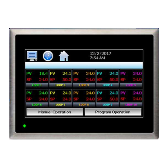
MCT-MC 5.5 Control Loops (Single Set point Operation) The Loop view screen provide direct viewing options for the control and monitoring of the MC control loops. The Loop screen allows the user to adjust the current loop set point (SP) and view the process variables (PV) and percentages of output (%) for each loop (when viewing up to 5 loops). -
Page 56: Historical Minimum And Maximum
MCT-MC 5.5.1.1 Historical Minimum and Maximum The MC monitors and stores the minimum and maximum process value reached during operation for each loop in the system. The current historical values can be viewed by pressing the process value display field for the desired loop. -
Page 57: Manual Operation
MCT-MC 5.5.1.2 Manual Operation The Manual Operation button displays a “slide out” window providing access to all events programmed for the system. To turn each event and its corresponding output on or off, simply press the button associated with the event. -
Page 58: Overview Screen
MCT-MC 5.5.2 Overview Screen The Overview provides a list of all loops configured in the system. It is accessed from the home “View” menu. If the MC is configured as a single loop system only loop one will be shown. The screen allows manual set point entry for each loop by touching the respective loop tag name or PV, SP and %Out display field. -
Page 59: Process Monitoring
MCT-MC 5.6 Process Monitoring The Loop and Overview screens provide the current process values of the MC. In order to view the process inputs over time, the MC provides real-time charts. Four user configurable charts are provided with up to eight plot points per chart. -
Page 60: Chart Setup
MCT-MC 5.6.1.1 Chart Setup To configure a chart, press the “Set” button in the upper right corner of the display. The setup screen will be shown. To assign channels to the chart, simply touch the on/off button for the desired items in the list to select them. -
Page 61: System Alarms
MCT-MC Once all settings have been made, press the “Return” button to return to the channel selection screen. Press the “Save” button to store the current channel and axis entries or the “Cancel” button to exit chart setup without altering the current chart settings. If channel selections or the time period for the chart has changed, all current chart data will be cleared when the new entries are saved. -
Page 62: Alarm File
MCT-MC 5.7.2 Alarm File The Alarm File screen is accessed from the home “View” menu. It displays all alarms for any given day. The MC can store daily alarm files for a period of a year or longer (time based on storage usage for data history). Each time an alarm occurs on the MC, the alarm is written to a file. -
Page 63: Automatic Ramp/Soak Program Operation
MCT-MC 6 Automatic Ramp/Soak Program Operation A ramp/soak program is a set of instructions (set points and events) programmed as a timed sequence of steps. When a program is run, the MC executes each step of the program automatically, in sequence, based on the time duration and settings for each step. -
Page 64: Entering A Ramp/Soak Program
MCT-MC The pop-up “Edit” icon menu provides the following functions: Copy Copies current step data including events. Paste Pastes previously copied step data to the current step. Step Events Copies and pastes current step events to all following steps. Holdback Limits Sets holdback limit value (set once only per program). -
Page 65: Setting Step Type
MCT-MC 6.1.1 Setting Step Type Programs are entered as a sequence of steps which define the set point and length of time that a loop should take to reach the set point (ramp) or remain at a set point (soak). The ramp and soak units can both be set for hours/minutes or minutes/seconds or one can be set for hours/minutes while the other is set for minutes/seconds. -
Page 66: Ramp/Soak Time Units Selection
MCT-MC NOTE: A step time of zero can be entered for a step to implement an immediate set point change. When coupled with a hold back condition on the following step, there is no need to know the time it takes for the process to reach set point. -
Page 67: Setting Step Events
MCT-MC If a ramp step was entered in the previous selection of “u/hr” for example, a ramp rate entry of 10 degrees per hour will become 10 degrees per minute if the ramp selection is changes to “u/min”. When time unit selections are changed, all steps must be reviewed in order to make sure the actual ramp rate or time length for each step is set to the desired length. -
Page 68: Setting Hold Events
MCT-MC NOTE: The step events must be set individually for each step. Even though a ramp/soak program may be in operation, if the events are not set, the associated loop control output will not turn on. To make setting step events quick and easy, the MC provides the “Step Events” function from the “Edit” menu. When selected, all event selections of the current step will be copied to all following steps. -
Page 69: Setting Jump Steps
MCT-MC The MC uses “band” type holdback operations. This means the MC will be in hold mode when the loop process value is above or below the loop set point by the entered holdback limit value during step operation. 6.1.5 Setting Jump Steps This feature allows the program to jump back to a previous step in order to repeat certain sections of a program. -
Page 70: Setting The End Step
MCT-MC 6.1.6 Setting the End Step All programs require that the last step is entered as an “End” step type regardless of the length (2 to 64 steps) of the program. The end step type provides a cycle count entry which makes it easy for the operator to repeat an entire program without having to enter a jump step. -
Page 71: Starting An Automatic Ramp/Soak Program
MCT-MC 6.2 Starting an Automatic Ramp/Soak Program All automated program operating functions are accessed via the Program Operation screen. This screen can be accessed by pressing the “Program Operation” button on the Loop view screen or by pressing the “Run” button on the program Entry screen. -
Page 72: Hold/Resume Ramp/Soak Program Operation
MCT-MC To stop a program, select “Stop” from the Program Operation window. When a program is stopped, the loop set point and events will revert back to the single set point (static mode) values that were entered prior to the program being started. -
Page 73: Monitoring Automated Ramp/Soak Program Operation
MCT-MC 6.3 Monitoring Automated Ramp/Soak Program Operation The program Status view provides all information regarding the operation of a program for each control loop configured in the system. The Status field indicates the current operating mode of the program, i.e., On, In Hold and Off. The Cycles field indicates the number of cycles left to be completed for the current jump loop. -
Page 74: Common Questions About Ramp/Soak Program Operation
MCT-MC 6.4 Common Questions About Ramp/Soak Program Operation 1. How do I start or run a ramp/soak program? To select and start a program, use the Program Operation window which can be accessed from the Loop view and program Entry screens. All start, stop and hold operations, program edit and select and program settings are available from this windows. -
Page 75: Security
MCT-MC 7 Security The MC security model provides an administrator with the tools to add up to 30 users to the system. Each user must have a unique ID, full name and password. Four user levels are provided which include system, user, supervisor and administrator levels. -
Page 76: Adding Users
MCT-MC 7.1 Adding Users The “New” user tab provides the ability to add up to 30 users to the system. Select the type of user from the drop down list (System, User, Supervisor or Administrator). Press each field to add the user ID, full name and password (no spaces allowed, 5 character minimum and 16 characters maximum). -
Page 77: Setting User Access
MCT-MC 7.3 Setting User Access The “Access” tab provides the administrator the ability to assign rights to each user level (System, User, Supervisor and Administrator). To enable or disable specific program functions (user rights) for each user level, select the user right from the list and press the corresponding on/off button for the user level you want to change access rights for. - Page 78 MCT-MC User Right Menu Location Description Auto Tune Device/Settings/View/Tuning enable or disable loop control Automatic Tune button Program Operate Program/Run, Hold, Stop actions applies to all program control menu selections; does not affect digital Inputs configured for same action Recovery Device/Settings/Offline/Set/Recovery logic when running an automated ramp/soak program when power lost &...
-
Page 79: Setting Security Options
MCT-MC 7.4 Setting Security Options The security “Options” tab provides the administrator the ability to set the global security options. The Password Aging Days field is a global for all users. Password aging starts from the day the user is entered into the system. -
Page 80: Audit Trail
MCT-MC 7.5 Audit Trail The audit trail viewer is accessed by selecting “Audit” from the Security menu. It displays all user actions that affected the system for any given day. The MC can store daily audit files for a period of a year or longer (time based on storage usage for data history). -
Page 81: Data Logging
MCT-MC 8 Data Logging The MC data logging features are accessed via the home ‘Data” menu item. The system data logging provides the ability to select individual points for logging, view data log files and start/stop logging operations. The logging ability of the MC provides an easy-to-use, convenient method to obtain electronic data without the need for additional data acquisition equipment. -
Page 82: Selecting Points For Logging
MCT-MC 8.1 Selecting Points for Logging In order for the data logging function of the MC to operate, the user must first select what variables are to be logged to the data file. To choose which points are to be logged, select “Assign” from the Data menu. Press the on/off button for each item to toggle it on/off. -
Page 83: Calculating Log File Size
MCT-MC The Interval (secs) field is used to set the rate at which points are written to the log file which equates to the sample rate in seconds. When the “Fixed Interval” option is turned on, the logging interval will be automatically set to record at minute intervals based on the number of days set for the file. -
Page 84: Reviewing Historical Data
MCT-MC 8.3 Reviewing Historical Data Historical files can be opened and viewed using the historical viewer. In order to view a historical data file, it must first be opened by selecting “Open” from the File menu. Once the file has been opened, the MC can automatically plot the first eight channels of the historical data file or the user can choose to cancel the plot and select which channels should be plotted as well as adjust the specific time period to plot. - Page 85 MCT-MC user to correct the problem. The ‘X’ and ‘Y’ axis scales are set to auto scale based on current values for each plot channel so no user action is required. The historical graph provides the same zoom feature as the real-time charts so the user can zoom in on a particular area of the historical plot by dragging their finger across the screen to draw a rectangle around the desired plot area.
-
Page 86: Usb File Transfer
MCT-MC 8.4 USB File Transfer A quick note about file storage; data and setup files (programs, alarm log and audit trail files) need some maintenance every now and then. After a period of time, storage devices fill up and files require backup or file deletion when no longer needed. - Page 87 The FDC Data Viewer program is a free Windows accessory program that allows users to view, plot and print data files and is available from Future Design Controls or any manufacturer that markets the MC product. It is required when using the digital signature feature of MC.
-
Page 88: Ftp/Fileweb/Dataweb Interface
MCT-MC 8.5 FTP/FileWeb/DataWeb Interface The FTP/WAN screen allows the user to configure automatic back-up of all data files contained in the MC memory to a user designated FTP or secure FileWeb site (https://). When enabled, the MC will automatically back up all data log files, alarm files and audit trail files at 2:00AM each day. With the optional delete files selection, the MC will then automatically delete the files from its internal memory after back up. -
Page 89: More About Ftp, Fileweb And Dataweb Interfaces
MCT-MC For example, if FTP or FileWeb is used and the “root” path at the server is “Files” and the MC files will be transferred to this directory, the “Sever” field will contain the text “Files”. If there is a directory inside of the server root “Files”... - Page 90 Port = 21 Port used at MC and open at DataWeb server. NOTE: An IT professional with experience is required for DataWeb server setup. Future Design Controls does not support server side programming or setup but can offer 3 party resources to assist with or handle complete server side projects.
-
Page 91: Fileweb/Dataweb Server Components And Requirements
A.2 of the Appendix. Web Development Support: Future Design Controls does not support or develop custom server side web solutions. We can offer 3rd party resources to assist customers in these development requirements. Logging... -
Page 92: Fdcutil.com Web Site For Ftp, Fileweb And Dataweb Testing
8.6 FDCUtil.com Web site for FTP, FileWeb and DataWeb Testing The FDCUtil web site is a Future Design Controls http/https site that allows customers to create a free account and test the FTP, FileWeb and DataWeb interfaces offered on the MC. The site automatically deletes files every 2 hours since this is a test site only and cannot be used for permanent web storage of files or data. - Page 93 MCT-MC If you do not have a user already setup, click on the “Sign Up” link which will show the following page: Enter information in the Name, UserName, Password and Confirm Password fields. The UserName, Password and Confirm Password fields will not allow space characters. Logging - 93 - FDC MCT-MC...
- Page 94 MCT-MC Once logged in, the main FDCutil site will be displayed with tabs for Data (DataWeb), Files (FileWeb) and FTP Files (FTP). These tabs can be clicked on and will display data after transfer from the MC device. After 2 hours, the data will be deleted from each section or the data can be manually deleted using the “Delete Data”...
- Page 95 MCT-MC FTP Files Page: The FTP files page, accessible from the “FTP Files” menu item, lists the files in the customer’s FTP data directory. These are only the files in the customer’s directory, not all uploads. The user can delete the files from this page.
- Page 96 MCT-MC Data Files Page (FileWeb): The data files page, accessible from the “Files” menu item, lists the files in the customer’s data directory. These are only the files in the customer’s directory, not all uploads. The user can delete the files from this page. FileWeb sample setup using FDCutil.com: To setup the MC for use with the FDCutil.com FileWeb server, go to the FTP/WAN screen on the MC and enter the following data into the screen fields.
- Page 97 MCT-MC Database Data Page (DataWeb): Once logged in, the customer will be shown the database data page. If data has been uploaded to the database, it will be displayed on this page. They can also delete data records. Choices from the Data link allows the user to view tabular data only or tabular data with a trend of the data at the top of the page.
-
Page 98: Annotation
MCT-MC If the data log interval rate is set for 60 seconds, the MC will populate the database with a single set of records (PV, SP, %Out determined by data log/server setup) once every 60 seconds. If the data log interval rate is set for 120 seconds, the MC will populate the database with a single set of records (PV, SP, %Out determined by data log/server setup) once every 120 seconds. -
Page 99: Add\View Digital Signatures
MCT-MC 8.8 Add\View Digital Signatures The Signature screen allows the user to add digital signatures to historical data log files and view any digital signatures currently associated with the loaded historical log file. When a historical data file is loaded, the Signature screen will display any signatures currently associated with the file. -
Page 100: Device Settings
MCT-MC 9 Device Settings This section covers the use of extended controller features that enhance the functionality of the system. To gain access to the MC setup options, select “Settings” from the home Device menu. The Device Settings menu provides navigation to the following functions: View menu Tuning: Provides access to manual loop tuning. -
Page 101: Tuning
MCT-MC 9.1 Tuning The loop Tuning screen allows for manual and automatic tuning of the MC control loops. Tuning parameters should only be manually adjusted by skilled users familiar with proportional control. Improper settings can result in control loop instability and equipment damage. The loop automatic tune function is the recommended method of loop tuning. -
Page 102: Heat/Cool (Bimodal) Control
MCT-MC 9.1.2 Heat/Cool (Bimodal) Control When a loop is programmed for heat/cool operation, the values of the Cooling PB and Dead Band affect the way the heat and cool outputs work together to control the process. The Cooling PB is measured in % of the proportional band with a range 50-300. Set cooling PB to 100% to begin and examine the cooling effect. -
Page 103: Setpoint Limits
MCT-MC The Alarm Message is the text notification that appears on the Alarm screen when the alarm activates. This message can be edited (up to 25 characters maximum) so that the alarm message more accurately describes what the alarm means. NOTE: The MC supports a total of 30. -
Page 104: Event Names
MCT-MC 9.4 Event Names The Event names screen allows the user to change the names of the system events in order to describe what function they perform. The event names are limited to nine alphanumeric characters. To change the name of the event, select the event by touching its current tag name in the list. Press the “Edit” button and enter the new tag name using the alpha-numeric keypad and press “Done”... -
Page 105: Communication Settings
MCT-MC 9.6 Communication Settings The “Comms” screen provides settings for the Modbus serial interface, web server and VNC interfaces. It also provides the MC IP address, which is required for using the VNC or web server interfaces. For more information regarding the use of the MC data communications interfaces, see Section 11, Communications. -
Page 106: Email
MCT-MC 9.7 Email The MC email server has the ability to send alarm messages to email and SMS addresses. Up to 30 addresses can be programmed into the system. Each one can be configured to receive emails, SMS text messages or both. -
Page 107: Email Settings
MCT-MC 9.7.3 Email Settings The “Settings” tab provides access to the email server configuration, which is how the MC is able to connect and send email messages over its Ethernet connection. Each field may have up to 50 characters. The Login field is used to enter the login name required by the MC to log in to your company’s mail server. You can use your login if one is not set up specifically for the MC on your network. -
Page 108: Email Message
MCT-MC NOTE: It is recommended to put some form of entry in this field. It can be left blank; however, many firewalls and spam filters will filter out messages without subject lines. That may prevent recipients from receiving the email. It can also be useful for identifying a particular unit on the factory floor. The Port field is used to set the port number that will be used on the device for email operations. -
Page 109: Offline
MCT-MC 10 Offline The Offline settings do not include the OEM setup of the MC. Refer to the documentation provided by your OEM regarding the MC configuration. Note that prior to entering offline setup, automated ramp/soak program operation and data logging must be manually stopped. The offline menu provides navigation to the following functions: View menu Settings:... -
Page 110: Power Recovery
MCT-MC 10.1 Power Recovery The Power Recovery setting allows the user to select how the system should restart in the event of a power failure while an automatic ramp/soak program was running. When power is restored, the MC will perform the selected recovery action. -
Page 111: Degrees C/F Units Selection
MCT-MC minutes for it to be saved. In order to insure that the system powers up with the desired set point, maintain power to the MC after a set point change for at least 6 minutes before removing power. 10.2 Degrees C/F Units Selection The MC can display temperatures in either degrees Centigrade or Fahrenheit. -
Page 112: Time Options
MCT-MC 10.3.1 Time Options Select the “Time Options” tab to configure the time zone and national time server clock settings. If the MC is connected to the internet, these settings can be used to have the MC automatically synchronize its time with one of the nationally provided time servers. -
Page 113: Language
MCT-MC If your locale utilizes daylight savings time, set the start and stop dates for daylight savings and turn on the “Daylight Savings Enable” option. Press the “Save” button to store the settings. MC will then automatically update its clock for daylight savings time. 10.4 Language The Language screen is used to select the language for all of the online help, menus and most static display fields. -
Page 114: Calibration
MCT-MC PC based application which allows the end user or OEM to create the translation files for the desired language selection. The translation files can then be copied to the MC control system in order to provide a more accurate or desired translation. 10.5 Calibration Each MC loop control is calibrated at the factory before shipment;... -
Page 115: Loop Calibration Offset
MCT-MC 10.5.1 Loop Calibration Offset The calibration offset provides a two point offset; a low point offset and a high point offset. The two point offset constructs a straight line (linear calibration) between the two points. To insure greatest accuracy, it is best to calibrate with the two points at the minimum and maximum operating ranges for the system. -
Page 116: Manual (Factory) Calibration
MCT-MC Once the calibration offset is complete, press the “Done” button to return to the main Calibration screen. 10.5.2 Manual (Factory) Calibration The manual calibration procedure is a two step process for RTD and linear inputs and a three step process for thermocouple inputs. - Page 117 MCT-MC If the new coefficient value is -1999 or 1999, the calibration failed. Check the source connections and insure the proper signal is applied. Press the Calibrate button to repeat the process or press the coefficient display/entry field and enter the previous coefficient value recorded to return the loop/limit back to its previous state.
-
Page 118: Rtd And Linear Input Calibration
MCT-MC Once the input has been verified to display the proper value according to the input reference signal, reconnect the control sensor to the loop control and press the “Done” button. This will return to the main Calibration screen. 10.5.2.2 RTD and Linear Input Calibration When the loop input is configured with an RTD or linear input, pressing the “Perform Manual Calibration”... - Page 119 MCT-MC Step 2 of the procedure is calibrating the span of the A to D converter. To calibrate the input high coefficient, adjust the resistance source to 300 ohms (for RTD input) or 20mA (for current input). If calibrating a voltage input, adjust the voltage source to 60mV for 0-60mV input, 1Vdc for 0-1Vdc input, 5Vdc for 0-5/1-5Vdc input or 10Vdc for 0-10Vdc input.
-
Page 120: Display Settings
MCT-MC 10.6 Display Settings The Display screen provides access to the touch screen calibration utility, back light settings and alarm volume adjustment. The Alarm Volume adjusts how loud the internal alarm buzzer of the MC will be when activated under an alarm condition. -
Page 121: Backlight Settings
MCT-MC Once complete, the calibration utility will provide a notification message that the new calibration settings have been measured and to touch the screen to register the new calibration data; just touch anywhere on the screen to close the window and return to the MC application to resume normal operation. 10.6.2 Backlight Settings The backlight settings allow the user to adjust the screen brightness as well as set a time period for dimming the backlight after a period of inactivity which can extend the life of the display. -
Page 122: Configuration
MCT-MC The brightness of the display during operation is set by adjusting the “ON” slider. The default setting is 100. The “OFF” slider is used to adjust the brightness of the display during periods of inactivity. The default setting is 10. Note that a setting of zero (0) does not completely turn off the backlight. To enable the backlight dimming function, place a check in the “Automatically turn off backlight.”... -
Page 123: Importing An Oem Default Configuration
MCT-MC When the Export button is pressed, the MC configuration data will be written to the USB memory device. The export file function will use the name entered in the text field to the right of the export button and create a directory on the memory stick with that name, to contain the configuration data. -
Page 124: About Mct-Mc
MCT-MC Hidden Import Factory Defaults Button To import a factory default configuration, insert the USB memory device containing the desired configuration file. Next to the “Home” icon is a hidden button. Tap the location repeatedly 10 times within a period of 4 seconds. -
Page 125: Exit Application
MCT-MC 10.9 Exit Application The “Exit” Application screen allows the user to quit the MC runtime software and return to the CE.Net operating system. This operation is NOT recommended with the exception of users who are in charge of system configuration due to the danger of editing or removing files by accident. -
Page 126: Communications
MCT-MC 11 Communications This section provides instructions on how to use the MC communication interfaces. As a standard, the MC is equipped with both an Ethernet interface and an RS232 serial interface for user communications. 11.1 Ethernet Communications The MC provides two forms of Ethernet communication interfaces for monitoring and controlling the system across a network. -
Page 127: Configuring The Mc Network
MCT-MC The most commonly overlooked source of problems is cabling. Not all cables are created equal. Electrical noise generated by factory equipment or other electrical equipment in the area, could easily corrupt transmitted data over the network and cause devices to “lock up” or shut down the VNC server, both of which then require the MC to be shut down and restarted to clear the problem. - Page 128 MCT-MC Hidden taskbar application icon From the desktop, double-tap the hidden icon at the top left of the screen to provide access to the taskbar application. Press the ‘Show Taskbar’ button in order to show the taskbar and then press the ‘Quit’ button to exit the taskbar application.
-
Page 129: Setting A Static Ip Address
MCT-MC The MAC address is displayed as the first item (Physical Address). Once the address has been recorded, close the network information windows and cycle power to the MC in order to restart the system and return to normal operation. 11.1.2.2 Setting a Static IP Address In order to set a static IP address for the MC on a network, it requires you to exit the MC application and enter the “Network and Dial-up Connections”... - Page 130 MCT-MC From the desktop, double-tap the hidden icon at the top left of the screen to provide access to the taskbar application. Press the “Show Taskbar” button in order to show the taskbar and then press the “Quit” button to exit the taskbar application.
-
Page 131: Using The Web Server
MCT-MC From the Connection window, select the current network connection by double-tapping the connection icon to enter its property window. DO NOT create a new connection. The Ethernet Drivers property window will allow you to set the IP address as well as name primary and secondary DNS and WINS servers from the Name Servers tab if necessary. - Page 132 NOTE: Contact your network administrator prior to enabling the web server of the MC. Company policy may prohibit the use of web servers for security reasons. Future Design Controls is not responsible for the use of, nor makes any claims as to the security of the web server interface over your network. The use of the web server is the responsibility of the end user.
-
Page 133: Using The Vnc Server
VNC server to stop responding and/or shut down requiring power to be cycled to the MC in order to reboot the system and restart the server. Future Design Controls has tested and recommends the use of RealVNC’s viewer. It has been tested for compatibility with the MC and a free version can be obtained from http://www.realvnc.com/... - Page 134 MCT-MC On the Display tab, make sure the scaling is set to “No scaling” and the checkbox for “Adapt to network speed (recommended)” is checked. Next, select the Inputs tab and deselect all entries except for “Enable mouse input” and “Rate-limit mouse move events”.
-
Page 135: Recommended Vnc Viewer Settings For Tablets
“automatically detect” or “server decides”. If the client is still unable to connect, try default encoding of Hextile and set the color option to limited colors such as 256 bit color. Future Design Controls does not write or create VNC clients (3rd party software), so final selection of client and testing is the end user responsibility. -
Page 136: Accessing The Mc Through A Vnc Viewer
MCT-MC 11.1.4.3 Accessing the MC through a VNC Viewer The following examples are based on the use of the RealVNC viewer for PC/MAC. Once the default settings have been entered, just enter the IP address and port number for the MC, and click the “Connect” button to access the MC over the network. - Page 137 MCT-MC Once the connection is established, the current MC display will be shown on your desktop. The image will be a duplicate of what is on the MC. As you manipulate the screen, the display of the MC will also be manipulated so that any local operator will be able to see what is happening and vice versa.
-
Page 138: Serial Communications Option
MCT-MC 11.2 Serial Communications Option The MC serial interface uses Modbus RTU protocol. Any device used to communicate with the MC over the serial interface must use this protocol. The communication address and parity can be set on the communications settings screen. All other communication settings are fixed. -
Page 139: Alarm Codes And Troubleshooting
MCT-MC 12 Alarm Codes and Troubleshooting This section provides explanations of standard MC alarms to help in diagnosing and resolving the alarm conditions. Note that the information provided here covers standard alarms only, and not alarms configured by the OEM. If you are unable to diagnose a problem through the use of this guide, contact your OEM for further assistance. - Page 140 MCT-MC Alarm Monitor Description Explanation/Corrective Action “tagname” outputs 1 and 2 incorrectly (error code 4) Indicates that the control loop configuration for the loop control configured. indicated by “tagname” is not valid and must be corrected to clear the alarm. Check and correct setup values of output 2, PB, TI and output 1.
-
Page 141: Appendix
MCT-MC Appendix A.1 Communications The MC control is equipped with Modbus RTU as its standard protocol. This section is intended to provide the user with a basic understanding of serial communications and how to interface with the MC. Numbers in the format “0x00”... - Page 142 MCT-MC ASCII Character Chart Char Code Decimal Binary Char Code Decimal Binary Ctrl @ 00000000 Shift 2 01000000 Ctrl A 00000001 Shift A 01000001 Ctrl B 00000010 Shift B 01000010 Ctrl C 00000011 Shift C 01000011 Ctrl D 00000100 Shift D 01000100 Ctrl E 00000101...
-
Page 143: Serial Communications
The MC is provided with a default parity setting of Even in order to be compatible with Future Design Controls’... -
Page 144: Interface Standards
MCT-MC A.1.3 Interface Standards An interface is a means for electronic systems to interact. It’s a specific kind of electrical wiring configuration. It has nothing to do with how data is sent over that connection. The two most common interfaces used today are RS-232, which provides a simple 1 to 1 connection and RS-485, which provides a multi-drop connection where more than one device can be placed on the same line. - Page 145 There is no need to rework software or install new drivers. US Converters 405 W. Fairmont Dr. Tempe, AZ 85282 E-mail: mail@usconverters.com www.USconverters.com Part # XS201A RS232 to RS485 Converter Future Design Controls 7524 West 98th Place Bridgeview, IL 60455 Phone: 888-751-5444 Fax: 888-307-8014 E-mail: csr@futuredesigncontrols.com www.futuredesigncontrols.com...
-
Page 146: Protocol
MCT-MC A.1.5 Protocol Protocol describes how to initiate an exchange. It also prevents two machines from attempting to send data at the same time. There are a number of different data communications protocols, just as there are different human cultural protocols that vary according to the situation. The protocol portion of the MC communications is very important, because it provides a quality of communication that others often don’t have. - Page 147 MCT-MC Example Cyclical Redundancy Checksum (CRC) Algorithm unsigned int calc_crc(unsigned char *start_of_packet, unsigned char *end_of_packet) unsigned int crc; unsigned char bit_count; unsigned char *char_ptr; /* Start at the beginning of the packet */ char_ptr = start_of_packet; /* Initialize CRC */ crc = 0xFFFF;...
-
Page 148: Creating Your Own Modbus Application
MCT-MC A.1.6 Creating Your Own Modbus Application Listed below are a few of the more common software packages that claim to support Modbus RTU protocol. This list is provided as informational only. Contact the software manufacturer for more information on applying their software. -
Page 149: Packet Syntax
MCT-MC A.1.7 Packet Syntax Each message packet begins with a one-byte controller address, from 0x01 to 0x1F. The second byte in the message packet identifies the message command: read (0x03); write single (0x06) or write multiple (0x10). The next “n” bytes of the message packet contain register addresses and/or data. The last two bytes in the message packet contain a two-byte Cyclical Redundancy Checksum (CRC) for error detection. - Page 150 MCT-MC Write Register Command (0x06) This command writes a value to a single register. This command is to be used for setting control values in the MC. To set multiple values, repeat the command for each data location. nn nn nn nn nn nn Packet sent to the MC:...
- Page 151 MCT-MC Write Registers Command (0x10) This command writes values to multiple registers in sequential order. It is used for automatic program download only to transmit program data one step at a time to the MC. See the Automatic Program Parameters section for the list of registers and their use.
-
Page 152: Error Checking
MCT-MC Exception Responses When the MC cannot process a command, it returns an exception response and sets the high bit (0x80) of the command. 0x01 illegal command 0x02 illegal data address 0x03 illegal data value nn nn Packet returned from the MC: controller address (1 byte) command + 0x80 exception code (0x01 or 0x02 or 0x03) -
Page 153: Transmitting And Receiving Messages
MCT-MC A.1.9 Transmitting and Receiving Messages In order to reliably communicate with the MC, it is important to develop an efficient means of transmitting and receiving messages. Modbus is a structured protocol and it must be properly followed. It is recommended, if possible, to locate an existing communication driver to incorporate into your software. - Page 154 MCT-MC Read 2 bytes from serial port and check value of second byte Read Write Exception Command Command Response (0x03) (0x06/10) (0x8_) Read 1 byte from serial Read remaining 8 bytes Read remaining 3 bytes port and obtain number of from serial port to obtain from serial port to obtain data bytes in message.
-
Page 155: Mct-Mc Loop Control Data Registers
MCT-MC A.1.10 MCT-MC Loop Control Data Registers Some of the values contained in the MC loop control register base contain bit oriented values. This means that each bit of the word indicates an on/off status for a specific setting or condition. In handling these values, it is recommended that the word be converted to its binary equivalent. -
Page 156: Control Registers
The design of the serial interface also allows the MC to connect to Future Design Conrtols’ Envision software. The software is free of charge and provides a host of features and is compatible with all FDC products. Using the P-Series controller selection in EnVision, each loop controller of the MC can be configured in EnVision as individual P-Series controls. - Page 157 MCT-MC Data Range Register Address Parameter Description Type High Unit Time Remaining in Current Step 99.59 (0x008A) 9999 (0x008B) Cycles Remaining for Current Loop 10000=infinite Command Code (0x008E) Notes: R/W Specifies readable/writable data, R specifies read only data and W specifies a write only control value.
- Page 158 MCT-MC Note: Auto tune may not be available depending upon the loop Parameter Description configuration. If auto tune operation is not available, the loop controller Value will revert back to static mode. When auto tune operation completes normally, the loop controller will revert back to static mode. Program Run Program Hold Only one mode can be set at time.
-
Page 159: Automatic Program Registers
MCT-MC Parameter Description Value No Error Illegal Setup Values Comm Error – Bad Function Code Comm Error – Register Out of Range Comm Error – Write Read Only Data Comm Error – Out of Range Data Holdback Time Out Auto Tune Error Input Type Requires Calibration EEPROM Error Cold Junction Failure... - Page 160 MCT-MC The first 5 registers of the program (header step) contain specific settings related to the program. These include the program number, hold back band, ramp units and dwell units. Data Range Register Parameter Description Address Type High Unit Program Selected for View (0x0056) Hold Back Band (0x0057)
- Page 161 MCT-MC Parameter Description Value Hours and Minutes Minutes and Seconds Units/Minute Units/Hour Parameter Description Value Hours and Minutes Minutes and Seconds Parameter Note: The last step of an automatic program must be an end step. If the Description Value last step is not an end step, the program will not run correctly and/or a program download error will occur and the program will not operate.
-
Page 162: Starting An Automatic Program
MCT-MC A.1.10.3 Starting an Automatic Program Automatic programs are sent to the MC in a step-by-step process. The download sequence must be followed in proper order and must complete without errors to be valid. If a write error is detected during the transfer of a program from a PC to the MC (no response from MC or NACK returned), the program download must be aborted and restarted. - Page 163 MCT-MC Starting a Program -20 second pause – (MC clears program buffer) Send program to MC one step at a time with a minimum 1 second pause between write commands: Send program header – 86 thru 90 Is the - 1 second pause - program Send step 1 data –...
-
Page 164: Ftp, Fileweb, Dataweb Requirements/Installation
MCT-MC A.2 FTP, FileWeb, DataWeb Requirements/Installation A.2.1 Introduction The following describes the system requirements, components, and an installation guide for the FDC Cloud service and website. The FDC cloud service provides the ability to upload data from FDC devices to cloud storage for backup and/or further analysis. -
Page 165: Data Transfer Service Installation
MCT-MC futuredesignEntities ConnectionString - Found in the <connectionStrings> element, this string provides connection information to the MySQL database. Its format is similar to: <connectionStrings> <add name="futuredesignEntities" connectionString="metadata=res://*/Models.MySQLModel.csdl|res://*/Models.MySQLModel.ssdl|res://*/Model s.MySQLModel.msl;provider=MySql.Data.MySqlClient;provider connection string="server=127.0.0.1;database=futuredesign;user id=root;password=password;oldguids=True"" providerName="System.Data.EntityClient" /> </connectionStrings> In the IIS Manager, add a website. Set the website’s physical path to the folder you created. An App Pool will be created with the site. -
Page 166: File Transfer Service Configuration (Fileweb)
MCT-MC A.2.9 File Transfer Service Configuration (FileWeb) Now that the FDDataService web service is setup, the folders should look like: Uploaded log files will be saved to the files folder. If there are any errors, logs of those errors will be saved in the logs folder. -
Page 167: Database Transfer Service Configuration (Dataweb)
MCT-MC A.2.10 Database Transfer Service Configuration (DataWeb) The database service will store uploaded data logs into a database table. There are some required settings in web.config to point the service to the correct data table and map file column names to database fields. The connection string to the database was setup in the previous section. - Page 168 MCT-MC NOTE: When configuring the MC multi-loop controller, the device data file tagnames for Date, Time, ID1, ID2 and UserName are automatically assigned and cannot be edited. The individual loop names are configurable by the user when setting up the controller (i.e. Loop1, Loop2, etc...). The MC appends a space character and the text “PV, SP and Out”...
- Page 169 MCT-MC DataMapID CustomerID FileColumn FieldName MC loop name configured by user at MC SvpTest Temp Out TempOut Temp (UserID or (Field must match (Field can be (assigned by user RemoteUserID user configured named anything in config) used during login) tagname + with no space spaceChar + “Out”) characters)
-
Page 170: Profile Recovery Detail
MCT-MC A.3 Profile Recovery Detail The following will provide a detailed explanation of program recovery operation for the MC. Program Power Recovery 1. Static Mode When power is cycled the program will be terminated. The current control set point and manual events will return to the previous static set point and event activation that were used prior to the program being started. - Page 171 MCT-MC i. If the process value has not exceeded the target set point for the ramp step, the time remaining will be dependent upon the programmed ramp rate and the difference between the process value and the target set point of the step. If ramp time units are used, i.e., MM.SS or HH.MM, the ramp rate is calculated by using the difference between the set point of the previous step and the set point of the current ramp step divided by the step time to get a rate of change in units/time.
-
Page 172: Touch Screen Interface Specifications
MCT-MC A.4 Touch Screen Interface Specifications Technical Specifications Description Details Size 4.3" Resolution (W X H in pixels) 480 x 272 Display type TFT, Wide touch Screen Colors 65,536 Touch screen Type Resistive analog Active display area (W X H mm) 95 X 54 MTBF back light at 25 0C 30,000 hrs... - Page 173 MCT-MC Standards, Certificates and Approvals Description Details UL approval UL 508 and CSA C22.2 No.142 Low Voltage Directive 2006/95/EC EMC Directive 2004/108/EC Requirements for Emission EN 61000-6-4 :2007 Requirements for Interference Immunity EN 61000-6-2 :2005 Tick mark for Australia AS/NZS CISPR 11:2004 FCC Part 15, Subpart B, Class A NOTE: The table above shows the approvals that may be available.
- Page 174 MCT-MC LCD specifications Description Details Touch operations 1,000,000 times using R 0.8 Polyacetal stylus with force 250g Vibration test 10-55 Hz, Stroke: 1.5mm, 2 hrs. for each direction of X, Y, Z Shock test 100 G, 6 ms, +/- X, +/- Y, +/- Z, 3 times for each direction Typical viewing angle Vertical (up/down), 50°...
-
Page 175: Power Supply Specifications
MCT-MC A.5 Power Supply Specifications DIN Rail Mount Power Supply Specifications Appendix - 175 - FDC MCT-MC... - Page 176 MCT-MC FDC MCT-MC - 176 - Appendix...
- Page 177 MCT-MC Open Frame Power Supply Specifications Appendix - 177 - FDC MCT-MC...
- Page 178 MCT-MC FDC MCT-MC - 178 - Appendix...
-
Page 179: Power-On Delay Relay Specifications
MCT-MC A.6 Power-On Delay Relay Specifications [GE1A-C10HA110] Appendix - 179 - FDC MCT-MC... - Page 180 MCT-MC FDC MCT-MC - 180 - Appendix...
-
Page 181: Ordering Specifications
MCT-MC A.7 Ordering Specifications MCT-MC Sample Part Numbers The MCT-MC consists of up to eleven individual part numbers. These include the display (Item 1) and loops #1 through #10 (Items 2 through 11). Item # Product Sample Part Number Description Display MCT-4ML-01-U00 FDC-0450-1011-000BN 4.3”... - Page 182 MCT-MC Items #2-11: B42 Loop Control Board Order Matrix # (1) Power Input 4: 90-250 VAC, 47-63 HZ 5: 11-26 VAC or VDC (consult factory for availability) (2) Signal Input 1: Standard Input Thermocouple: J, K, T, E, B, R, S, N, L, C, P RTD: PT100 DI, PT100 JIS Voltage: 0-60mV 5: 0-10V, 0-1V, 0-5V, 1-5V...
- Page 183 Replacement SD Memory Card SD-4ML 8GB High Capacity SD Memory Card (preloaded with MCT-MC application software) Printed Operators Manual Part Number (MCT-MC_4.3_User_Manual.pdf) MCT-MC 4.3 User Manual USB Cables & Accessories WPUS-BAX-05M USB panel mount adapter WPCVR-USB USB waterproof IP67 cover (for above) DG9025MF3 25 pin 90°...
-
Page 184: Support And Warranty Information
The CE Net version of the HMI, and firmware versions of the loop and limit controls of the MC control system are proprietary and only available directly from Future Design Controls. Using similar or like components obtained from a source other than Future Design Controls will cause unexpected operation and/or malfunction of the MC control system. Any attempts to do so will be at the user’s own risk and void any and all claims or warranties with Future... - Page 185 Design controls are not considered Future Design Controls products and cannot be used with Future Designs SOFTWARE. Using Future Design's SOFTWARE with any other manufacturer (or distributor) of hardware is a violation of this license and applicable copyright laws. The SOFTWARE is considered in "use" when it is installed into permanent or temporary memory (e.g.
- Page 186 Future Design Controls facilities and to conform at that time to the specifications set forth in the relevant Future Design Controls manual, sheet or sheets for a period of one year after delivery to the first purchaser for use.
Need help?
Do you have a question about the MCT-MC 4.3 and is the answer not in the manual?
Questions and answers