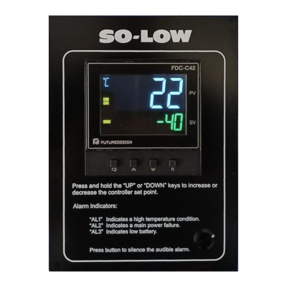
Summary of Contents for Future Design FDC-C42
- Page 1 FDC-C42 Chamber Controller Installation – Setup – Operation - Service FDC-C42 Chamber Controller Manual Rev C October 2022...
- Page 2 The FDC-C42 incorporates a (SPST) control relay output and three (SPST) alarm relay outputs. Two of the alarm relays (AL1 for temperature and AL2 for power failure) are prewired together in order to facilitate faster installation and connection to external alarm relays for remote indication and sounding the on-board audible alarm (wired separately).
-
Page 3: Installation
2 Installation Dangerous voltages capable of causing death can be present within this instrument. Before performing installation or troubleshooting procedures, the power to the equipment must be switched off and isolated. Units suspected of being faulty must be disconnected and removed to a properly equipped workshop for test and repair. - Page 4 2.2 Mounting Make the panel cut out as per the dimensions shown in the following figure: 4 of 13...
- Page 5 2.3 Wiring Electrical power in an industrial environment contains a certain amount of noise in the form of transient voltage and spikes. This electrical noise can enter and adversely affect the operation of microprocessor-based controls. For this reason, we strongly recommend the use of shielded thermocouple extension wire which connects the sensor to the controller.
- Page 6 The control assembly is provided with the alarm relay outputs, alarm silence push-button and audible alarm pre-wired to aid in assembly. The pre-installed jumpers combine alarm outputs one and two (for temperature and power failure) together so that only a single connection is required in order to activate the external alarm relays.
- Page 7 Power Supply C42 Control Assembly Terminal Description Terminal Description Output (V-) N (DC-) Output (V+) L (DC+) Bat Low (-) EI COM Bat Low (+) The control relay is a single pole / single throw (SPST) configuration. The control relay will energize and the contacts will close when the process value is at or above the set point value.
-
Page 8: Sensor Installation Guidelines
Control Board C42 Control Assembly Terminal Description Terminal Description Call For Cooling OP1 (COM) Call For Cooling OP1 (NO) Power Failure Relay EI COM Power Failure Relay 2.3.2 Sensor Installation Guidelines Proper sensor installation can eliminate many problems in a control system. The sensor should be placed so that it can detect any temperature change with minimal thermal lag. - Page 9 2.3.3 Alarm Relay Output /Audible Alarm Connection to the alarm relays and audible alarm require external control relays that are not part of the control assembly. One relay is utilized to provide remote contacts for customer connection for remote alarm indication (shown as CR1 in the following diagram) and is optional.
-
Page 10: Operation
3 Operation The FDC-C42 controller is programmed by using four keys on the front panel. The available function keys are listed in the following table: Touch Function Description Press and release to increase the current control set point (while in... - Page 11 3.1 Control Output Hysteresis The control type for relay output 1 is pre-configured for cooling (direct action). The control hysteresis (prompt O1HY) is safe-sided. The control relay’s output will operate in the following manner. For example, the set point is -80° (F or C), and the control hysteresis value is 2.0. The control relay’s output will be energized until the temperature reached -82°...
- Page 12 3.3 Power Status Alarm Indicators The FDC-C42 events inputs 1 and 2 and alarm outputs 2 and 3 are pre-configured to act as power supply status alarms. Event input 1 and alarm output 2 (AL2) are utilized to indicate a power failure. Under normal operation, event input 1 will be activated indicating power is present.
- Page 13 3.4 Input Offset Calibration Each unit is calibrated at the factory before shipment. The user can still modify the calibration in the field. The basic calibration of the controller is highly stable and set for life. User calibration allows the user to offset the permanent factory calibration in order to: •...


Need help?
Do you have a question about the FDC-C42 and is the answer not in the manual?
Questions and answers