
Related Manuals for Future Design MCTB 4.3


Summary of Contents for Future Design MCTB 4.3
- Page 1 MCTB 4.3/7 User Manual MCTB 4.3/7 User Manual Rev. M May 2022 (MCT-4MA V1.3.1 / 7MA V1.1) Supersedes: Rev L (February 2022)
- Page 2 Your comments or suggestions on this manual are welcome. Please send them to: Future Design Controls, P.O. Box 1196, Bridgeview, Illinois, 60455 Telephone: +1 (888) 751-5444; fax: +1 (888) 307-8014 csr@futuredesigncontrols.com The MCTB 4.3/7 User Manual is copyrighted by Future Design Controls, Inc., © 2018, all rights reserved.
-
Page 3: Table Of Contents
2.1 Enclosure Guidelines ......................11 2.1.1 Locating the MCTB Touch Screen Interface .................. 11 2.2 Environmental Considerations .................... 12 2.3 Mounting Dimensions ......................12 MCTB 4.3” Touch Screen Interface ....................13 2.3.1 MCTB 7” Touch Screen Interface ....................14 2.3.2 2.3.3 MCTB Process Loop/Limit Controls .................... - Page 4 4.2.36 Ramp Rate Operation (MCTB 4.3” version 4MA V1.3 only) ............47 4.2.37 Ramp Rate Down Low/Upper Limit (MCTB 4.3” version 4MA V1.3 only) ........47 4.2.38 Ramp Rate Up Low/Upper Limit (MCTB 4.3” version 4MA V1.3 only) .......... 48 4.2.39 Setpoint 2 Format (MCTB 4.3”...
- Page 5 5.4 Notifications ........................107 5.5 Control Loops (Single Set point Operation) ..............108 5.5.1 Loop View ............................. 108 Ramp Rate Operation (MCTB 4.3” version 4MA V1.3 only) ..............108 5.5.1.1 Setpoint 2 Operation (MCTB 4.3” version 4MA V1.3 only) ..............110 5.5.1.2 5.5.1.3...
- Page 6 Setting Jump Steps ........................125 6.1.7 Setting the End Step ........................126 6.2 Starting an Automatic Ramp/Soak Program ..............127 Starting a Ramp/Soak Program at a Specific Time (MCTB 4.3” version 4MA V1.3 only) ... 128 6.2.1 6.2.2 Hold/Resume Ramp/Soak Program Operation ................129 6.3 Monitoring Automated Ramp/Soak Program Operation .............
- Page 7 MCTB 9.8.3 Email Settings ..........................171 9.8.4 Email Message ..........................172 10 Offline ........................173 10.1 Power Recovery ....................... 174 10.1.1 Recovery Interval .......................... 174 10.2 Degrees C/F Units Selection .................... 175 10.3 Clock Settings ........................175 10.3.1 Time Options ..........................175 10.3.1.1 Local Time Server Settings........................
- Page 8 MCTB A.4 Touch Screen Interface Specifications ................224 A.5 SmartIO Monitor Module Specifications................227 A.6 Expansion IO Module Specifications ................. 228 A.7 Power Supply Specifications ..................... 229 A.8 Power-On Delay Relay Specifications ................233 A.9 Ordering Specifications ..................... 235 A.10 Support and Warranty Information ..................238...
-
Page 9: What Is The Mctb
LAN/WAN using a PC, tablet or smart phone device. Future Design Controls’ “MCTB” provides a 4.3” color touch screen interface with standard “Smart Device” user interface features for multi-loop OEM control applications. All loop configuration and runtime user access is configurable at the device with no PC software required. - Page 10 MCTB The MCTB controller includes the following features: ACCESSIBILITY ALARMS • • Touch screen, “Smart Device” user interface (UI) with Up to 19 alarms, 10 soft configurable to B42 & L41, up to 30,000-hour (4.3”) or 50,000 (7”) LED display 3 alarm outputs per B42 and L41 up to 2 alarm outputs.
-
Page 11: Installation
MCTB 2 Installation All MCTB components are pre-loaded with all operating software and firmware before leaving the factory so it is ready to install when you receive it. Before beginning installation, completely read through this section as well as the following section (3. Power and Wiring) to gain an understanding of the entire installation process. Consider the installation carefully. -
Page 12: Environmental Considerations
MCTB Proper clearance must also be maintained above, below and on both sides of the interface to allow for heat dissipation and to facilitate mounting. A minimum of 2” is recommended. Note that additional space may be required below and to the right of the interface (looking from rear of unit) to accommodate the communications wiring depending upon the type of communication cables used. -
Page 13: Mctb 4.3" Touch Screen Interface
MCTB MCTB 4.3” Touch Screen Interface 2.3.1 All dimensions are in mm. Tolerance +/- 1 mm. Panel cutout: 123 x 99 DB9, Male Not Used LAN, Ethernet (RJ45) SD slot DB25, Female USB port Power supply NOTE: The MCTB will not operate properly without the SD card installed into the SD card slot on the back of the unit. -
Page 14: Mctb 7" Touch Screen Interface
MCTB MCTB 7” Touch Screen Interface 2.3.2 All dimensions are in mm. Tolerance +/- 1 mm. Panel cutout: 197 x 141 DB9, Male Not Used LAN, Ethernet (RJ45) SD slot DB25, Female USB port Power supply NOTE: The MCTB will not operate properly without the SD card installed into the SD card slot on the back of the unit. -
Page 15: Mctb Process Loop/Limit Controls
Future Design Controls B42 board level control. Refer to the FDC B42 manual for dimensions, appropriate mounting and installation instructions. The MCTB also provides for the connection and interface to a single Future Design Controls L41 limit control. Refer to the FDC L41 manual for dimensions, appropriate mounting and installation instructions. Use care in determining the proper location of the limit control. -
Page 16: Expansion Io Module
MCTB 2.5 Expansion IO Module The expansion I/O module (FDC630TA-DC) provides the option of adding an additional 16 digital inputs and 14 digital outputs to the MCTB. The inputs and outputs can be utilized as alarms, events, or for any number of uses within math/logic functions. -
Page 17: Wiring
MCTB 3 Wiring This section describes the methods and precautions for wiring the MCTB system components. • Turn off power to the MCTB before starting installation, removal, wiring, WARNING: maintenance and inspection of the MCTB controller. Failure to turn off power may cause electric shock, create a fire hazard or cause damage to the MCTB. - Page 18 MCTB In order to properly sense the loss of power, the time delay relay coil should be wired to the AC power source for the DC power supply of the MCTB. This will ensure that the MCTB is turned off/on at the proper times and prevent malfunction that can be caused by rising or falling voltage at the power supply output during power interruption.
-
Page 19: Connecting To The Mctb Interface
MCTB 3.2 Connecting to the MCTB Interface Power wiring lengths should be kept to a minimum, and it is preferable to have the power wiring run using a minimum of 18/2 twisted shielded cable. This keeps the “hot” and “common” wires paired to minimize the effects of external noise. -
Page 20: Process Loop/Limit Controller Communications
MCTB 3.2.1 Process Loop/Limit Controller Communications The loop/limit controls communicate with the MCTB touch screen using the RS485 communications port. This allows up to three B42 boards (or two B42 boards and one L41 limit control) to be connected using one 2-wire link. -
Page 21: Connecting To The Process Loop/Limit Controls
Connecting to the Process Loop/Limit Controls The MCTB is compatible with the Future Design Controls B42 board level process loop controls and the L41 ¼ DIN limit control. The input and output wiring to the individual loop(s) and limit control is dependent upon options ordered on each device as well as the intended application. - Page 22 MCTB NOTE: The connection requires a single twisted-pair cable that is daisy-chained from one MCTB to the next. When using shielded twisted-pair cable, be sure to ground only one end of the cable, preferably at the RS232 to RS485 network adapter. Allowing any other portion of the cable shield to come in contact with ground, or grounding both ends, will cause ground loop currents to flow in that section of the cable which can cause communication errors.
-
Page 23: Connecting To The Smart Io Monitor Module
MCTB 3.3 Connecting to the Smart IO Monitor Module Power connections should be made using minimum 18 AWG copper conductors (maximum wire size = 14 AWG). To make a connection, strip about ¼” of insulation off the end of the wire, turn the connector screw counterclockwise until the gap is wide open, insert the wire all the way in, and turn the screw clockwise until it’s tight. - Page 24 MCTB...
-
Page 25: Connecting To The Expansion Io Module
MCTB 3.4 Connecting to the Expansion IO Module Power and IO connections should be made using minimum 18 AWG copper conductors (maximum wire size = 14 AWG). To make a connection, strip about ¼” of insulation off the end of the wire, turn the connector screw counterclockwise until the gap is wide open, insert the wire all the way in, and turn the screw clockwise until it’s tight. -
Page 26: Configuring The Mctb
MCTB 4 Configuring the MCTB The MCTB Configurator is a powerful tool that is built in to the system. It is a program that allows the OEM or user to set up control system options for the MCTB runtime application. This allows for on-the-spot setup of the MCTB without the need for external hardware and software. - Page 27 MCTB The File menu provides selections of “Exit” and “About”. The exit function for the Configurator saves all settings and closes the Configurator application. The about selection displays version information for the Configurator application and configured control devices. It also includes selections for accessing the Loop Address Utility and Smart IO Comms Utility for use in setting up and connecting to B42 loop controls and the remote monitor module.
-
Page 28: Control Setup
MCTB setup, the output control functions of each device can be changed, so any equipment being controlled by the outputs should be placed in an “off” state, so that any modifications to output functions will not cause an unsafe condition or damage to equipment. IMPORTANT: Once all configuration settings are made, you must select “Exit”... -
Page 29: Loop Configuration
MCTB Three Loop When three loop is selected, the MCTB will be configured as a three-loop controller. Three B42 process loop controls must be attached and set for communications addresses of 1, 2 and 3 for proper operation. The Soft Alarms field is used to enter the number of soft alarms that will be provided on the system. A soft alarm is an alarm without a physical control output. -
Page 30: Tagname
MCTB 4.2.1 Tagname The Tagname entry allows the user or OEM to assign a specific name for each control loop, up to 11 characters in length. This name will be used throughout the MCTB runtime application and can be used to provide a more detailed description as to the function the loop provides. -
Page 31: Decimal Point
MCTB The input unit selections for temperature are mutually exclusive, i.e., selecting one will turn off the other. Once the desired temperature units have been selected, press the “Done” button to set the input units for the loop control board and return to the main Loop Configuration screen. 4.2.4 Decimal Point The Decimal Point entry allows the input precision to be adjusted between zero and one decimal digits for... -
Page 32: Event Input Function
MCTB 4.2.7 Event Input Function The Event Input Function is used to select the desired mode of operation for the digital input of the loop control board. The event input selections are mutually exclusive, i.e., selecting one will turn off the others. Once the desired function has been selected, press the “Done”... -
Page 33: Event Input Alarm Message/Annotation
The Activate SP2 function (MCTB 4.3” version 4MA V1.3 only) enables a secondary set point for the loop (see section 4.2.40 Setpoint... -
Page 34: Output 1 Failure Transfer
MCTB NOTE: The output function must be set to match the type of output ordered on the loop control board. Relay, triac and SSRD output types are used for on/off and time proportioning control. The isolated VDC and mA output types are used for linear control. The Heating on-off control function will turn on the output when the process value is below set point. -
Page 35: Output 1 On-Off Control Hysteresis
MCTB that this should not be used for extended periods of time as a runaway condition could occur if separate limit devices are not installed to ensure safe limits of operation by turning off the system should a limit be exceeded. If the output function is set for on-off control, the failure transfer can be set to have the output turn on (1) or turn off (0) when a sensor break occurs. - Page 36 MCTB The output can be set for cooling time proportioning or linear control, an alarm or an event. The output selections are mutually exclusive, i.e., selecting one will turn off the others. Once the desired function has been selected, press the “Done” button to set the output function for the loop control board and return to the main Loop Configuration screen.
-
Page 37: Output 2 Failure Transfer
MCTB 4.2.16 Output 2 Failure Transfer The output 2 failure transfer setting is used to set the value the output should go to if there is an input failure, i.e., sensor break. The output can be set for bumpless (-1) operation or a fixed percentage of output (from 0 to 100%) if proportioning or linear control is selected for the output function. -
Page 38: Output 3 Failure Transfer
MCTB The Alarm output function activates the Alarm 2 configuration settings for assigning the type of alarm logic to apply to output 3. When the alarm condition is active, the output will turn on. The Reverse alarm output function activates the Alarm 2 configuration settings for assigning the type of alarm logic to apply to output 3. -
Page 39: Output 4 Failure Transfer
MCTB The Alarm output function activates the Alarm 3 configuration settings for assigning the type of alarm logic to apply to output 4. When the alarm condition is active, the output will turn on. The Reverse alarm output function activates the Alarm 3 configuration settings for assigning the type of alarm logic to apply to output 4. -
Page 40: Output 4 Retransmit Low/High Scale
MCTB 4.2.24 Output 4 Retransmit Low/High Scale The output retransmit low and high scale can be set when the output 4 function is set for retransmit process or setpoint value. They are used to set the retransmit range of the output. The low scale value corresponds to the output low limit value and the high scale value corresponds with the output high limit value. -
Page 41: Alarm (1-3) Mode
MCTB low alarm occurs. When the process value rises above the control set point plus alarm set point plus the alarm hysteresis (PV < SV+ASP+AHY), the alarm is off. A Deviation band high/low alarm sets two trigger levels relative to the control set point value. For deviation band alarms, the alarm set point is entered as a positive value. -
Page 42: Alarm (1-3) Setpoint
MCTB When the alarm indication is set for Hide alarm status/settings, the alarm will be removed from the MCTB runtime application. The user will not be able to edit the alarm message or adjust the alarm set point. When the alarm activates, there will be no indication or message on the alarm screen and the audible alarm will not sound. -
Page 43: Setpoint At Start Of Automatic Program
MCTB For non-latching alarms (normal or hold mode), the programmed time delay is activated (timing begins) when the alarm setpoint is exceeded. The alarm delay will stop timing (and reset) if the PV = (Alarm SP – HY) (hysteresis). If the time delay times out and alarm setpoint is still exceeded, the output associated with the alarm will actuate. -
Page 44: Power Fail Recovery
MCTB The Final setpoint of automatic program selection will use the final set point value programmed on the end step of the program as the control set point when the program ends. The event status will be set to the previous static event selections that were used prior to program operation. -
Page 45: Communication Mode
MCTB The Continue automated program from last SP selection will resume the program from where it left off with the last set point set by the program at the time of power failure. The Continue automated program from PV selection will resume the program using the current process value at the time power is restored as the set point. -
Page 46: Loop Mode
MCTB NOTE: The failure transfer setting will override the Safety communications mode in the event that there is also a control input failure. For example, if the output 1 low limit value is set to 10% and communications is lost with the MCTB display, output 1 will operate at a fixed output value 10%. If the loop control input then fails and the failure transfer value is set to 20%, output 1 will then operate at a fixed 20% output. -
Page 47: Ramp Rate Operation (Mctb 4.3" Version 4Ma V1.3 Only)
Limits) in the runtime. This allows the user to adjust the rate at which the set point will ramp from the current process value to each set point entered. 4.2.37 Ramp Rate Down Low/Upper Limit (MCTB 4.3” version 4MA V1.3 only) The ramp rate down low and upper limit entries are used to define the minimum and maximum ramp rate the user can set for the rate of change of the loop set point under ramp rate operation when the set point is below the current process value. -
Page 48: Ramp Rate Up Low/Upper Limit (Mctb 4.3" Version 4Ma V1.3 Only)
MCTB 4.2.38 Ramp Rate Up Low/Upper Limit (MCTB 4.3” version 4MA V1.3 only) The ramp rate up low and upper limit entries are used to define the minimum and maximum ramp rate the user can set for the rate of change of the loop set point under ramp rate operation when the set point is above the current process value. -
Page 49: Limit Configuration
MCTB For temperature in degrees Fahrenheit or linear input types, with a decimal of 0 the values are -32767 and 32767. For one decimal point, the values are -3276.7 and 3276.7. For two decimal digits, the values are - 327.67 and 327.67 and for three decimal digits the values are -32.767 and 37.767. 4.3 Limit Configuration The Limit Configuration screen is accessed from the Setup menu. -
Page 50: Input Units
MCTB The input type selections are mutually exclusive, i.e., selecting one input will turn all other selections off. Once the desired input type has been selected, press the “Done” button to set the input type for the limit control and return to the main Limit Configuration screen. -
Page 51: Input Low/High Scale
MCTB 4.3.5 Input Low/High Scale The Input Low Scale and Input High Scale entries are used to set the input range for linear input types (VDC or mA). The entries are not available for temperature input types since they utilize a fixed range based on the sensor type. -
Page 52: Output 1 Hysteresis
MCTB The High limit control function will turn off the output when the process value exceeds the high limit set point. Once the process value is below the high limit set point and the alarm is reset, the output will turn on. The Low limit control function will turn off the output when the process value exceeds the low limit set point. -
Page 53: Alarm Function
MCTB The DC power supply output function must be selected when the output type ordered for the limit control is a transmitter power supply. The Alarm output function activates the alarm configuration settings for assigning the type of alarm logic to apply to output 2. -
Page 54: Alarm Mode
MCTB When Process value low alarm is selected and the process value is lower than the alarm set point (PV < ASP), a process low alarm occurs. When the process value is above the alarm set point plus the alarm hysteresis (PV >... -
Page 55: Alarm Setpoint
MCTB When the alarm indication is set for Hide alarm status/settings, the alarm will be removed from the MCTB runtime application. The user will not be able to edit the alarm message or adjust the alarm set point. When the alarm activates, there will be no indication or message on the alarm screen and the audible alarm will not sound. -
Page 56: Event Input Function
MCTB The Output goes off as unit fails selection will force the output off during failure regardless of the alarm activation status. The Output goes on as unit fails selection will force the output on during failure regardless of the alarm activation status. -
Page 57: Display Format
4.3.21 Restart Mode (MCTB 4.3” version 4MA V1.3 only) The Restart Mode entry is used to select the limit control state on power up. Once the desired mode has been chosen, press the “Done”... - Page 58 MCTB When Normal is selected (default mode) and power is applied, as long as the process value is not exceeding either the high or low limit set point, the limit output (OUT1) will be energized. If upon application of power, the process value is exceeding either the high or low limit set point, the limit output will not be energized.
-
Page 59: Monitor Configuration
MCTB 4.4 Monitor Configuration The Monitor Configuration screen is accessed from the Setup menu. The screen provides access to all monitor points as entered on the Control Setup screen. When more than one monitor point is configured, the left/right scroll buttons will be provided at the top right of the screen. These buttons can be used to scroll through all available monitor points in order to view/edit settings for each. -
Page 60: Input Units
MCTB NOTE: Each input is equipped with a slide switch for selecting voltage or current input type. The switch must be set properly according to the input type selection made. See section 3.3.1 Sensor Wiring for details on sensor wiring and switch settings according to selected sensor type. 4.4.3 Input Units The Input Units entry is used to select the temperature units for thermocouple input types. -
Page 61: Soft Alarm Configuration
MCTB 4.5 Soft Alarm Configuration The Soft Alarm Configuration screen is accessed from the Setup menu. The screen allows the user or OEM to program each soft alarm up to the total number entered on the Control Setup screen. When more than one soft alarm is programmed, the left/right scroll buttons will be provided at the top right of the screen in order to view/edit settings for each alarm. - Page 62 MCTB When the process value falls below the control set point plus alarm set point minus the alarm hysteresis (PV < SV+ASP-AHY), the alarm is off. Deviation Low The alarm is dependent upon the control set point and alerts the operator when the process deviates too far below the set point value.
-
Page 63: Math/Logic Configuration
MCTB The programmed time delay is activated (timing begins) when the alarm setpoint is exceeded. The alarm delay will stop timing (and reset) once the process value returns to non-alarm level. If the time delay times out and the alarm setpoint is still exceeded, the alarm will activate. 4.6 Math/Logic Configuration The Math/Logic Configuration screen is accessed from the Setup menu. - Page 64 MCTB Timer Type When Timer is selected, the equation will be utilized to obtain a true/false result to activate a time delay. The equation can then be selected as a timer input on another Logic equation as T1-T20 corresponding to the number of the math/logic equation 1-20.
- Page 65 MCTB S2_EvOut2 Loop 2 (slot 2) event output 2. If selected, the equation will be evaluated when the event output is activated. This selection is available when the output 2 function the B42 in slot 2 is configured for event, manual event only or math/logic event output only. S2_EvOut3 Loop 2 (slot 2) event output 3.
-
Page 66: Entering A Math/Logic Equation
MCTB The Result Shown selection is provided for Math equations. When on, the result of the equation is displayed on the Overview screen in the runtime and the value is also selectable for data logging and trending. When off, the value is not displayed in the runtime. The off selection is typically chosen if a derived value is required for a soft alarm, but is not something that needs to be displayed to the user. - Page 67 MCTB S2_PV Loop 2/Limit (slot 2) process value. S2_SP Loop 2 (slot 2) set point value. Only available a B42 is installed in slot 2. S2_%Out Loop 2 (slot 2) percentage of output. Only available a B42 is installed in slot 2. S3_PV Loop 3/Limit (slot 3) process value.
-
Page 68: Math/Logic Equation Examples
MCTB The error message will provide help in determining what is wrong with the equation; however, due to the number of possible combinations it is up to the user to ultimately evaluate the equation and verify its validity. Once the equation can be properly solved, pressing the “Done”... - Page 69 MCTB Parentheses First 4 x (5 + 3) – (4 / 2) (5 + 3) = 8 and (4 / 2) = 2 are evaluated first 4 x 8 – 2 4 x 8 = 32 is evaluated first since multiplication before addition 32 –...
-
Page 70: Square Root (Sqrt) Implementation
MCTB 4.6.2.2 Square Root (SQRT) Implementation To obtain the square root of a value or expression, you first activate the square root function by pressing the SQRT key. This appends the square root function “SQRT[“ to the current equation. The SQRT key will “lock” on as indicated by changing color. - Page 71 MCTB Examples: If either input is false, the output is false. If both inputs are true, the output is true. Inputs Output F = False (off) T = True (on) Nand If either input is false, the output is true. If both inputs are true, the output is false. Note: NAND is just what it implies, i.e., NOT AND.
- Page 72 MCTB If either input is true, the output is false. If both inputs are false, the output is true. Note: NOR is just what it implies, i.e., NOT OR. Inputs Output F = False (off) T = True (on) Latch When the trigger is active, the output follows the input.
-
Page 73: Advanced Boost Heat/Cool Logic Example
MCTB Comparison (Equals) If two values are the same, the output is true. Comparing values… As long as the set point of both loop 1 and 2 are equal, the output will be on. Comparing logic states… As long as the loop 1 and 2 event input states are equal, the output will be on, i.e., if both inputs are on or both inputs are off, the... - Page 74 MCTB Math/Logic 1 will be used for boost heat, so first we select “Logic” for the equation Type. For reference, the Tagname will be set to “Boost Heat”. The Trigger will be left at the default of “Always” since the output should activate any time the heating percentage of output is above 80%.
- Page 75 MCTB When the temperature percentage of output is less than -50, event output 4 of loop 1 will activate. When the percentage of output is above -50, the output will turn off. The two equations now provide the boost heat and cool functions required.
-
Page 76: Advanced Compressor Control Logic Example
MCTB 4.6.2.6 Advanced Compressor Control Logic Example Compressor control applications typically involve single or dual stage refrigeration systems. Dual stage systems are utilized in ultra-low temperature situations such as environmental test chambers or even heat treat applications where temperatures below -100°F (-73°C) are required. Typically, control schemes for environmental chambers tend to be more complex. - Page 77 MCTB We do not want to delay the start of the compressor too long, so as shown above s short delay of 10 second is used. The equation shown above defines the condition at which the time delay begins. Since we do not want the compressors activating unless the chamber is on, we begin with the chamber event (S1_EvOut3) having to be on which is loop 1 event output 3.
- Page 78 MCTB This equation is relatively simple (as shown below). First, we need to verify that the stage 1 output is activated (S1_EvOut4) which is loop 1 event output 4. Next, we only want stage 2 to activate if the humidity system is not on which is loop 2 event output 3 (NOT S2_EvOut3).
- Page 79 MCTB The final equation, Math/Logic 5, is for the stage 2 compressor output. It will essentially a duplicate of the stage 1 equation, but with one additional condition, i.e., the delay timer (math/logic equation 3) must also be expired. By duplicating the stage 1 equation and appending the requirement that the system 2 delay time has expired (represented as T5), the stage 2 compressor output will activate and deactivate under the same conditions as the stage 1 compressor, but also require the system 2 delay to be expired.
-
Page 80: Cascade Control Option
MCTB 4.7 Cascade Control Option Cascade control can be utilized when the control type is set for Dual Loop (+ Limit) or Three Loop. For the Single Loop (+ Limit) control type selections, the cascade control function selections are not accessible since cascade control requires two loops in order to operate. -
Page 81: Cascade Settings
MCTB The advantage of cascade control, like in the example above, comes down to isolating a process with relatively slow dynamics (like temperature, level, humidity) from some other relatively-fast process that has to be manipulated to control the slow process. If the heating elements were directly immersed in the product, then cascade control would most likely not be necessary as the heating elements would directly affect the product temperature. - Page 82 MCTB If the outer loop is configured for heat/cool operation, it will have an output of -100 to 100% where -100% is full cooling and 100% is full heating. If the lower and upper limits entered in the runtime on the Cascade screen are 0 and 50, an output of -100 to 100% on the outer loop will generate a set point of 0 to 50 on the inner loop.
-
Page 83: Expansion Io Module Option
MCTB To utilize this mode of operation, typically both the control outputs of the outer loop and inner loop are wired to the final control elements. The outer loop would control the valve for water flow, while the inner loop would control the valve for additive flow. This allows the operator to adjust the water flow as required for downstream processes and the inner loop will automatically adjust the required additive flow based on the actual water flow rate. -
Page 84: Input (8-23) Alarm Message/Annotation
MCTB The Automatic program run/abort function will start the currently loaded program from step 1 if not already running, upon activation of the input (an off to on transition). Deactivating the input (an on to off transition) will stop the program if it is currently running. The Automatic program hold/resume function will place a currently running program into hold when the input is activated (an off to on transition). -
Page 85: Output (32-45) Function
MCTB 4.8.3 Output (32-45) Function The output function selection is used to select the desired mode of operation for each digital output. Each output is provided with its own function selection. The output numbers correspond to the markings on the expansion IO module. -
Page 86: Event Timer Option
MCTB Event Timer Option The event timer option provides a countdown timer coinciding with the event 1 output. This provides simple, timed operation of the system for a preset period when more complex automatic program operation is not required. The Event Timer Option button toggles the option on and off. When enabled, the timer is automatically associated with event 1 and its corresponding output. -
Page 87: Functions
MCTB 4.10 Functions The MCTB functions are accessed from the Startup menu and allow the user or OEM to select which screens/menu items will be enabled (shown) in the MCTB runtime application. These functions can be used to customize the system to meet specific requirements. When functions are disabled at the Configurator level from the functions list, it will be disabled in the runtime software by removing the menu item or disabling the field so the operator cannot select the function or edit any corresponding settings related to the function. - Page 88 MCTB MCTB Function Runtime Menu Location Description Security Settings Security view/set security rights, view audit trails, user log on view security and audit status Notifications NOTE: If security is enabled, but system security is then disabled through this item, the user will be unable to log on.
- Page 89 MCTB MCTB Function Runtime Menu Location Description Alarm Settings Device\Settings\Set\Alarm access alarm settings NOTE: Alarms can be fully programmed in the Configurator and hidden in the runtime by disabling this function. The alarms will operate as programmed in the background removing all access by the operator. Email/SMTP Settings Device\Settings\Email\Email access to view/configure email settings...
-
Page 90: Startup View
MCTB 4.11 Startup View The Startup View screen is accessed from the Startup menu and allows the user or OEM to define which of the main view screens the runtime application will display when it first starts and when the “Home” icon is pressed. The available selections are Loop View, All View, Chart View, Alarm View and Alarm Log. -
Page 91: Event Names
MCTB 4.13 Event Names The Event Names screen accessed from the Tagnames menu and allows the user or OEM to edit the names of all configured event outputs. In order to access the screen, there must be at least one loop control output configured as an event. -
Page 92: Loop Address Utility
MCTB 4.15 Loop Address Utility In order for the MCTB to properly communicate with each of the loop control boards, they must be configured for the proper communications address. The factory default communication settings of the loop control boards are set for a communications address of one, which correspond to the proper settings for loop 1. For a single loop MCTB control system, no further settings are required. -
Page 93: Smart Io Communication Utility
MCTB 4.16 Smart IO Communication Utility The default communication parameters of the monitor module (new module or one that has factory reset applied) do not match the proper settings required to communicate with the MCTB. The Smart IO Communication Utility (accessed from the File menu) provides quick, easy method to configure the monitor module parameters via the touch of a button. -
Page 94: Basic Operation
MCTB 5 Basic Operation This section is designed to help guide the user through the MCTB touch screen interface and menu structure in order to navigate through the various operation, monitor and setup screens and gain an understanding of how to use them. Subsequent sections of this manual are tailored to the special features and functions of MCTB. -
Page 95: Event Timer Operation
MCTB 5.1.2 Event Timer Operation The event timer option in the MCTB configuration provides the OEM with a countdown timer connected to event 1 output. This provides simple, timed operation of the system for a preset period when more complex automatic program operation is not required. -
Page 96: Entering The Time And Starting The Timer
MCTB 5.1.2.1 Entering the Time and Starting the Timer Upon pressing the “Stopwatch” icon when the timer is not in operation, the numeric entry keypad will be shown. The run time is entered as a period of time in hours, minutes and seconds. To make time entry easy, the entry will automatically be formatted into time as the number keys are pressed. -
Page 97: Touch Screen Interface
MCTB 5.2 Touch Screen Interface The MCTB display is split into two sections; the icon bar and main display area. Icon Bar Main Display Loop View Screen IMPORTANT: Do not use any sharp or metal objects on the touch screen as they may damage the surface. Also, be sure that hands and fingers are free from oils or chemicals which may mar the surface of the touch screen. -
Page 98: Menu Navigation
MCTB 5.3 Menu Navigation The MCTB provides the user with the ability to select text-based menu navigation, much like the typical file menu system of a PC, as well as an icon-based navigation system like that of a “smart” device. The user can switch back and forth between the two from the Setup menu. -
Page 99: Home Menu
MCTB 5.3.1 Home Menu The home menu is the top level, default menu provided when MCTB first powers on. Pressing the menu (monitor) icon will display the main menu offering the selections shown below. 5.3.1.1 Text Based Home Menu The View menu provides navigation to all standard view screens. These include the Loop view, real time Chart, Alarm monitor, Alarm File and Overview control screens. -
Page 100: Icon/Slide Page Based Home Menu
MCTB 5.3.1.2 Icon/Slide Page Based Home Menu Slide page 1 provides navigation to all standard view screens. These include the Loop and Overview, Chart, Alarm monitor, and Alarm File. It also provides quick access to the MCTB Settings Data file functions which include file utilities, FTP\WAN back-up settings as well as the historical data viewer. -
Page 101: Device Settings Menu
MCTB 5.3.2 Device Settings Menu The device settings menu is provided when the user selects “Settings” from the main “Device” menu. See section 9 Device Settings for detailed information on these settings and their use. 5.3.2.1 Text Based System Setup Menu The View menu provides navigation to the manual loop Tuning screen. -
Page 102: Icon/Slide Page Based Device Settings Menu
MCTB 5.3.2.2 Icon/Slide Page Based Device Settings Menu Slide page 1 provides access to Navigation type, control loop set point Limits, Alarm set points, loop Tuning, Event tagname entry and Email server settings Messaging. It also includes access to the communications settings for the web page, VNC server and Modbus user communications. -
Page 103: Offline Menu
MCTB 5.3.3 Offline Menu The offline menu is provided when the user selects “Offline” from the device settings “Offline” menu. See section Offline for information on these settings and their use. NOTE: Offline settings can only be accessed when an automatic ramp/soak program is not running and data logging is turned off. -
Page 104: Icon/Slide Page Based Offline Menu
MCTB 5.3.3.2 Icon/Slide Page Based Offline Menu Slide page 1 provides navigation back to the device Settings menu, Clock, Display settings, About MCTB and Exit application screens, temperature Units selection, Language, import/export Configuration utility and input Offset calibration. Slide page 2 provides access to the automated program power... -
Page 105: Data Menu
MCTB 5.3.4 Data Menu The data log menu is provided when the user selects “Data” from the main “Data” menu. See section 8 Data Logging for information on these settings and their use. 5.3.4.1 Text Based Data Logging Menu The View menu provides access to the data file Annotation and digital Signature screens. -
Page 106: Icon/Slide Page Based Log Menu
MCTB 5.3.4.2 Icon/Slide Page Based Log Menu Slide page 1 provides access to the main Data log screen and to the log point Assignment screen where the user can select which items are to be logged. Historical data file functions are provided for Opening and Deleting historical files and viewing/setting data file Annotations and digital... -
Page 107: Notifications
MCTB 5.4 Notifications The notification window is a feature that can be accessed by pressing the date/time field in the icon bar. This window provides a snapshot of current MCTB activity. The notification window can be closed by pressing the date/time field again, or is automatically closed if the Menu, Home or a navigation arrow icon is pressed. -
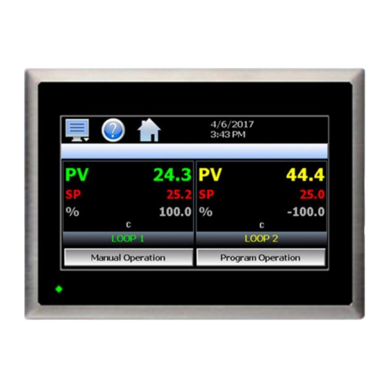
Page 108: Control Loops (Single Set Point Operation)
The loop name and loop units, shown at the bottom of each loop (or limit), will display the tagname and units as entered in the Configurator. Ramp Rate Operation (MCTB 4.3” version 4MA V1.3 only) 5.5.1.1 When a loop is configured for ramp rate operation, the “SP” label will provide additional status for the loop in regards to whether the set point is ramping up, down, or is stable at the target set point. - Page 109 MCTB Press SP tag to view ramp rate settings. Under ramp rate operation, when a set point is entered, the loop starts the ramp from the current process value and then continues to the target set point according to the rate up or rate down entry made on the set point Limits screen (see section Setpoint Limits).
-
Page 110: Setpoint 2 Operation (Mctb 4.3" Version 4Ma V1.3 Only)
Thus, it is up to the user to ensure that the program is written properly so that it does not exceed the maximum desired rate of change for the loop set point. Setpoint 2 Operation (MCTB 4.3” version 4MA V1.3 only) 5.5.1.2 A secondary set point can be configured for a loop and activated via the loop’s event input. -
Page 111: Historical Minimum And Maximum
MCTB IMPORTANT: If set point 2 is configured as an actual set point, it will override the set point defined by the operating ramp/soak program. If set point 2 is defined as a deviation, the offset will be continuously applied to the set point defined by the operating program. If the loop is not under program control, the offset will be applied to each user set point entry. -
Page 112: Manual Operation
Press the desired icon for quick access to any program operation. The “Select” icon can be used to select any program stored for quick run operations. The “TOD Start” icon (MCTB 4.3” version 4MA V1.3 only) allows the current loaded program, or newly selected program, to be started at a specific time and date. -
Page 113: Overview Screen
MCTB 5.5.2 Overview Screen The Overview screen displays all loops, the limit and events on a single screen for quick access to all system parameters. Press any loop to access the “slide out” keypad for set point entry. Press an event button to turn the output on and off. -
Page 114: Chart Setup
MCTB to a minimum of 6 seconds. Thus, the update rate will vary from a minimum of 6 seconds (for time periods of 72 minutes or less) up to a maximum of 120 seconds for 1440 minutes (24 hours). The Labels button allows the user to cycle through each of the configured plot channels to determine what each colored plot represents as well as view the current value without having to return to the Single or Dual view screens. -
Page 115: System Alarms
MCTB Time Period Adjusts the displayed time period for the graph. The allowable range is from 4 to 1440 minutes (24 hours). Maximum The maximum value sets the maximum range of the vertical access with a minimum value of -32,760 and a maximum of 32,760. Minimum The minimum value sets the minimum range of the vertical access with a minimum value of -32,760 and a maximum of 32,760. -
Page 116: Alarm File
MCTB The alarm will be removed from the list when cleared by the operator by pressing the “Clear” button. Only alarms that are not currently active in the system can be cleared from the alarm list. IMPORTANT: If a loop control is in manual mode or in automatic tune and the reset button is preset, the alarm reset will terminate automatic tune or manual mode and place the loop back into normal operation. - Page 117 MCTB The Disk icon next to the Email icon allows the user to save the currently opened data file to a USB memory device connected to the MCTB. NOTE: If no alarms occurred on a given day, an alarm file will not be created for that day. The alarm list will display up to 650 alarm files.
-
Page 118: Automatic Ramp/Soak Program Operation
MCTB 6 Automatic Ramp/Soak Program Operation A ramp/soak program is a set of instructions (set points and events) programmed as a timed sequence of steps. When a program is run, the MCTB executes each step of the program automatically, in sequence, based on the time duration and settings for each step. -
Page 119: Entering A Ramp/Soak Program
MCTB The pop-up “Edit” icon menu provides the following functions: Copy Copies current step data including events. Paste Pastes previously copied step data to the current step. Step Events Copies and pastes current step events to all following steps. Holdback Limits Sets holdback limit values for each loop (set once only per program). -
Page 120: Setting Step Type
MCTB 6.1.1 Setting Step Type Programs are entered as a sequence of steps which define the set point and length of time that a loop should take to reach the set point (ramp) or remain at a set point (soak). The ramp and soak units can both be set for hours/minutes or minutes/seconds or one can be set for hours/minutes while the other is set for minutes/seconds. -
Page 121: Ramp/Soak Time Units Selection
MCTB NOTE: A step time of zero can be entered for a step to implement an immediate set point change when programmed for ramp. If holdback is enabled on a step, a minimum step time of 10 seconds 0.10 (mm:ss) or 1 minute 0.01 (hh:mm) is required to ensure that the holdback condition can recognize the process change in order for holdback to operate. -
Page 122: Ramp Rate/Soak Time Units Selection
MCTB NOTE: A ramp rate entry is only available for single loop MCTB systems because the length of time for the step to complete is based upon the change in set point and the rate at which the set point is to ramp. Ramp units of time are still available for selection on single loop systems if time entry is preferred over rate. -
Page 123: Setting Step Events
MCTB 6.1.4 Setting Step Events For each step of the program, the user can select which events are to be on during the step. To edit step events, press the “Event” button on the program Entry screen. This will display the Event list for the program step. -
Page 124: Holdback Limits
MCTB all inputs reach the wait set point, the step time countdown will resume and not be held up again for the remainder of the step. When at least one hold condition set in a step, an asterisk ‘*’ will appear before the word “Hold”... -
Page 125: Wait For Set Point
MCTB 6.1.5.2 Wait For Set Point When the wait for condition is selected for one or more inputs, an additional entry for the wait set point (Wait SP) will be provided at the bottom of the hold selection list. This set point is common for all inputs chosen to wait for. -
Page 126: Setting The End Step
MCTB To program a jump step, select jump for the step type and enter the step number that you want the program to jump back to along with the total number of times the jump is to be made (by pressing each row in the list). A cycle count of one indicates that no jump will be made since one cycle is completed upon reaching the jump step. -
Page 127: Starting An Automatic Ramp/Soak Program
MCTB 6.2 Starting an Automatic Ramp/Soak Program All automated program operating functions are accessed via the Program Operation screen. This screen can be accessed by pressing the “Program Operation” button on the Loop view or Overview screens or by pressing the “Run”... -
Page 128: Starting A Ramp/Soak Program At A Specific Time (Mctb 4.3" Version 4Ma V1.3 Only)
MCTB Starting a Ramp/Soak Program at a Specific Time (MCTB 4.3” version 4MA V1.3 only) 6.2.1 A program can be set to start at a specific date/time by pressing the TOD Start icon. Similar to pressing the Run icon, if a program is already loaded, the user will be able to set the date/time for current program to start without entering a start step. -
Page 129: Hold/Resume Ramp/Soak Program Operation
MCTB If power is lost to the system while a program is in TOD start, and then returns after the scheduled date/time at which the program was to start, the program will begin operation from the moment power is restored. 6.2.2 Hold/Resume Ramp/Soak Program Operation At any time during the operation of a program, it can be manually placed into hold. -
Page 130: Common Questions About Ramp/Soak Program Operation
MCTB The name of the running program, or current program loaded to the MCTB loop controls, will be shown at the bottom center of the screen. If no program has been loaded, the field will be empty. IMPORTANT: If the set point does not match the set point programmed for the step, check the set point limits for the loop (see section 9.3 Setpoint Limits). -
Page 131: Security
(System, User, Supervisor or Administrator). NOTE: At least one administrator must be added to the system (and maintained) in order to enable security. Two-Factor Authentication (2FA) is available on the MCTB 4.3 version 4MA V1.3 only. -
Page 132: Viewing Users
MCTB Press each field to add the user ID, full name and password (no spaces allowed, 5 characters minimum and 16 characters maximum). If two-factor authentication is enabled (see section 7.4 Setting Security Options), a valid SMS number must be entered in the 2FA SMS Number field for the user. This allows the system to send a security code to the user’s personal device during the log in process. -
Page 133: New Password Entry
MCTB To delete a user, select the user from the list and press the “Delete” button. Likewise, to change the password for a user, select the user from the list and press the “Password” button. 7.2.1 New Password Entry To change a password, select the desired user by touching the User ID in the list box and press the ‘New Password’... -
Page 134: Security System User Access
MCTB 7.3.1 Security System User Access Shown below is a list of the available user rights, where to find the menu item(s) applicable to the user right and a description of what it applies to. Note that the OEM configuration allows many menu items to be disabled; in which case the menu for a specific user right may not be shown. -
Page 135: Setting Security Options
MCTB User Right Menu Location Description Default Configuration Device/Settings/Offline/System/ function to clear system configuration and reset all to Configuration; Reset Default blank (default) state for reconfiguring Configuration button Exit (run mode) Device/Settings /Offline/System/Exit; prevents MCTB application from being stopped “Exit application. (automatic mode startup).”... -
Page 136: Two-Factor Authentication (2Fa) - Mctb 4.3" Version 4Ma V1.3 Only
Two-Factor Authentication (2FA) - MCTB 4.3” version 4MA V1.3 only 7.4.1 2FA is an extra layer of security used to make sure that the person trying to gain access to the system is who they say they are. -
Page 137: Audit Trail
MCTB 7.5 Audit Trail The audit trail viewer is accessed by selecting “Audit” from the Security menu. It displays all user actions that affected the system for any given day. The MCTB can store daily audit files for a period of a year or longer (time based on storage usage for data history). -
Page 138: Data Logging
MCTB 8 Data Logging The MCTB data logging features are accessed via the home ‘Data” menu item. The system data logging provides the ability to select individual points for logging, view data log files and start/stop logging operations. The logging ability of MCTB provides an easy-to-use, convenient method to obtain electronic data without the need for additional data acquisition equipment. -
Page 139: Selecting Points For Logging
MCTB 8.1 Selecting Points for Logging In order for the data logging function of the MCTB to operate, the user must first select what variables are to be logged to the data file. To choose which points are to be logged, select “Assign” from the Data menu. Press the on/off button for each item to toggle it on/off. - Page 140 MCTB If more than one MCTB utilizes the same entries, the data from all units with the same ID’s will be combined under the one ID in the database. This will render the data unusable as there will be no way to split the data between the different units and know which data points are from each unit.
-
Page 141: Calculating Log File Size
MCTB 8.2.1 Calculating Log File Size The MCTB saves the log file in a text-based format (.csv), so the amount of memory consumed for each reading is dependent upon the number of digits required to accurately display the value (1 byte per character). This optimizes memory usage but also makes calculating an exact file size difficult. -
Page 142: Plotting Historical Data
MCTB Any point from the data file can be selected along with the vertical axis to be used for each channel to be plotted. Select channels from the list by turning them on or off and use the “Left” and “Right” axis buttons to assign the selected item to the left or right axis for the plot range. - Page 143 MCTB Pressing the “Legend” button will provide the user with channel information by displaying the names of the selected plot channels, which axis they are associated with and the color used to display the plot channel. Pressing the button again will toggle the display back to the historical chart. NOTE: When pressing the Legend button to toggle between the historical chart and the legend screen, it may take several seconds for the chart to become visible depending on the size of the data file and number of channels selected to plot.
-
Page 144: Usb File Transfer
MCTB 8.4 USB File Transfer The “Utilities” section of the MCTB interface provides all the functionality required for retrieving files and maintaining the internal SD memory card. The internal SD card should not be removed from the MCTB interface. Any change to SD directory structure (moving or deleting files with a PC) may cause the MCTB interface to stop operating and a new SD card will need to be ordered. -
Page 145: Recommended File Maintenance
NOTE: The USB memory stick must be inserted into the USB port for any of the file utility operations to function. It is recommended to only use memory sticks certified by Future Design Controls for use with the MCTB. Future Design Controls has tested and validated these memory devices for proper operation and performance. -
Page 146: Ftp/Fileweb/Dataweb Interface
MCTB If a file name is specified or logging on Program operation is enabled, each file will begin with the same prefix. Thus, multiple files can begin with the same 8 characters this limiting the maximum number of files that can be stored. - Page 147 MCTB The Type drop down is used to select the FTP/WAN interface. Choices are FTP, FileWeb and DataWeb. The IP Add field is used to enter the IP address of the FTP/FileWeb/DataWeb site that MCTB is to interface with. The User field allows you to enter a user name for site access. When the MCTB connects to the FTP/FileWeb/DataWeb site, the user name will be used to identify the connection.
-
Page 148: More About Ftp, Fileweb And Dataweb Interfaces
MCTB 8.5.1 More About FTP, FileWeb and DataWeb Interfaces FTP servers (File Transfer Protocol) have been around for many years and can be installed on local or network machines. The FTP server allows a client (MCTB) to transfer files to the FTP server once installed. This allows for manual and automatic backup of data from the MCTB. - Page 149 (see section 8.2 Starting/Stopping Data Logging) NOTE: An IT professional with experience is required for DataWeb server setup. Future Design Controls does not support server-side programming or setup but can offer 3 party resources to assist with or handle complete server-side projects.
-
Page 150: Fileweb/Dataweb Server Components And Requirements
8.6 FDCUtil.com Web site for FTP, FileWeb and DataWeb Testing The FDCUtil web site is a Future Design Controls http/https site that allows customers to create a free account and test the FTP, FileWeb and DataWeb interfaces offered on the MCTB. The site automatically deletes files every hour since this is a test site only and cannot be used for permanent web storage of files or data. - Page 151 MCTB Once you have created and verified your account, you can log in to the website. Once logged in, the main FDCUtil website will be displayed with tabs for Data (DataWeb), Files (FileWeb), FTP Files (FTP) and Configurations. These tabs can be clicked on and will display data after transfer from the MCT device. Every hour, the data will be deleted from each section (except for Configurations) or the data can be manually deleted using the “Delete”...
- Page 152 To setup the MCTB for use with the FDCutil.com FTP server, go to the FTP/WAN screen on the MCTB and contact Future Design Controls technical support for FTP access. The FTP section of FDCutil.com is used for tech support (pass/fail) testing only when validation if required at a customer site (customer site not working for some reason).
- Page 153 MCTB Data Files Page (FileWeb): The data files page, accessible from the “Files” menu item, lists the files in the customer’s data directory. These are only the files in the customer’s directory, not all uploads. The user can delete the files from this page. FileWeb sample setup using FDCutil.com: To setup the MCTB for use with the FDCutil.com FileWeb server, go to the FTP/WAN screen on the MCTB and enter the following data into the screen fields.
- Page 154 MCTB Database Data Page (DataWeb): Once logged in, the customer will be shown the Data page. If data has been uploaded to the database, the “Device ID” drop-down menu will contain the list of units (according to the ID#1 and/or ID#2 entries as made on the Data logging screen).
- Page 155 MCTB The available data can also be viewed in graph format. Hover the mouse over the Data tab and selections for Trend and Table will be provided. Once Trend is selected, choose the desired unit from the Device ID menu. Place a check next to each available point you want to plot and click the Update Chart button.
-
Page 156: Annotation
MCTB DataWeb sample setup using FDCutil.com: To setup the MCTB for use with the FDCutil.com DataWeb server, go to the FTP/WAN screen on the MCTB and enter the following data into the screen fields. Make sure to replace the “custName” and “custPassword” text below with the actual user name/password entered during the FDCutil.com signup process. -
Page 157: Add\View Digital Signatures
MCTB To add an annotation to the running log file, touch the “Entry” field at the bottom of the screen and enter the message (up to 16 characters maximum). Press the “Add” button and the message will be added to the current log file. -
Page 158: Device Settings
MCTB 9 Device Settings This section covers the use of extended controller features that enhance the functionality of the system. To gain access to the MCTB setup options, select “Settings” from the home Device menu. The Device Settings menu provides navigation to the following functions: View menu Tuning: Provides access to manual loop tuning. -
Page 159: Tuning
MCTB 9.1 Tuning The loop Tuning screen allows for manual and automatic tuning of the MCTB control loops. Tuning parameters should only be manually adjusted by skilled users familiar with proportional control. Improper settings can result in control loop instability and equipment damage. The loop automatic tune function is the recommended method of loop tuning. -
Page 160: Heat/Cool (Bimodal) Control
MCTB Once the process has stabilized, if the process value is lower than the set point by 5° for example, and 20.0 is used for the proportional band, that is equal to an offset of 25%. Thus, the PB offset would be increased by 25% to compensate for the set point offset in the process. -
Page 161: Alarms
MCTB set between two and five, the PID set entries are then written to the loop control according to the activation set point and current process value. The PID Set Activation Set Point is the process value above which the PID set is utilized. PID sets two through five have an activation set point. -
Page 162: Limit Alarms
MCTB The alarm numbers, Alarm #, identify the alarms currently shown on the screen along with the alarm description which contains the loop name that the alarm is assigned to as well as the alarm type. The left and right scroll buttons at the upper right of the screen will be shown if more than two alarms are available so that the user can access each alarm by pressing left or right to go to the previous or next alarm. -
Page 163: Setpoint Limits
MCTB When the alarm is locked, the “Alarm Message” description will be replaced with “(Locked)”. Pressing alarm set point entry field will display a dialog indicating that the field is locked. In order to unlock a limit alarm set point press and hold the alarm set point field. After approximately 4 seconds, the “(Locked)” descriptor will be replaced with the standard “Alarm Message”... -
Page 164: Cascade
Consult your OEM or equipment installer regarding the maximum set point limits permitted for your system. Ramp Rate Limits (MCTB 4.3” version 4MA V1.3 only) 9.3.1 When the loop is configured for ramp rate operation, the set point Limit screen will provide fields for the adjustment of the set point rate of change as well as the deviation hold. -
Page 165: Process Cascade Mode
MCTB 9.4.1 Process Cascade Mode This mode uses the low and high set points as the upper and lower range for the secondary loop set point. The percentage of output of the primary loop is converted to calculate a linear set point between these two values. The Process Low and Process High values are limited to the minimum and maximum values for the lower and upper set point limits of the secondary loop as defined by the OEM in the MCTB configuration. -
Page 166: Ratio Cascade Mode
MCTB 9.4.3 Ratio Cascade Mode This mode provides a single set point which is used to calculate the secondary loop set point according to the primary loop process value. This is typically use din blending applications where the flow rate of the primary fluid is monitored and controlled via the primary loop, and the secondary loop is to add a fractional amount of another substance to the mix. -
Page 167: Communication Settings
MCTB selection is made, the other will be de-selected. The button indicator for the active selection will illuminate to show the current selection. The Notifications Navigation selection allows the user to enable/disable navigation from the notifications window. When enabled and the user presses a row in the notifications window, the screen associated with the item in the selected row will be shown. - Page 168 MCTB The Modbus Address and Parity settings are used to configure the serial interface for user communications. Valid addresses are 1 to 247. The parity setting allows the serial port to be set for Even, Odd or no parity (None). The Modbus Address is also used to specify the unit ID for Modbus TCP communications.
-
Page 169: Ethernet Settings
MCTB 9.7.1 Ethernet Settings The “Ethernet” screen provides settings for the network interface of the MCTB. It is accessed by pressing the Ethernet button on the Communications screen. The MAC address field displays the media access control address (physical address) of the MCTB. This is a unique identifier for the network hardware of the MCTB and cannot be changed. -
Page 170: Email
MCTB 9.8 Email The MCTB email server has the ability to send alarm messages to email and SMS addresses. Up to 30 addresses can be programmed into the system. Each one can be configured to receive emails, SMS text messages or both. When an alarm occurs, MCTB will send an alert to the specified address for each user in the list. -
Page 171: Email Settings
MCTB 9.8.3 Email Settings The “Settings” tab provides access to the email server configuration, which is how the MCTB is able to connect and send email messages over its Ethernet connection. Each field may have up to 50 characters. The Login field is used to enter the login name required by the MCTB to log in to your company’s mail server. You can use your login if one is not set up specifically for the MCTB on your network. -
Page 172: Email Message
MCTB MCTB will connect to the mail server, then request a secure connection. Once the secure connection has been established, the MCTB will transmit the email over the secured connection. The MCTB does not support the implicit mode of securing the connection which is typically done over port 465. -
Page 173: Offline
MCTB 10 Offline The Offline settings do not include the OEM setup of the MCTB. Refer to the documentation provided by your OEM regarding the MCTB configuration. In order to enter offline setup, automated ramp/soak program operation and data logging must be manually stopped. NOTE: Upon entering offline setup, all loop control outputs, event outputs and alarm outputs will be set to their corresponding OFF state. -
Page 174: Power Recovery
MCTB 10.1 Power Recovery The Power Recovery setting allows the user to select how the system should restart in the event of a power failure while an automatic ramp/soak program was running. When power is restored, the MCTB will perform the selected recovery action. -
Page 175: Degrees C/F Units Selection
MCTB 10.2 Degrees C/F Units Selection The MCTB can display temperatures in either degrees Centigrade or Fahrenheit. To change the temperature display units, select “Units” from the offline Set menu. Press the button for the desired temperature units to make the selection. The choices are mutually exclusive so when one selection is made, the other will be de-selected. -
Page 176: Local Time Server Settings
MCTB To enable the national time server, select your time zone and which time server you wish to use from the drop- down menu selections. Turn on the “NTP Service Enable” option and press the “Save” button. The MCTB will then synchronize its time with the selected national time server at 2:00AM each day. -
Page 177: Language
MCTB If your locale utilizes daylight savings time, set the start and stop dates for daylight savings and turn on the “Daylight Savings Enable” option. Press the “Save” button to store the settings. MCTB will then automatically update its clock for daylight savings time. NOTE: If the NTS time server setting is enabled, and the selected time zone uses daylight savings time, daylight savings must be properly configured and enabled or the clock will not show the correct time. -
Page 178: Loop Calibration Offset
MCTB Press the Perform User Calibration Offset button to access the settings for applying an offset to the loop or limit factory calibration. This is the recommended method of calibrating the inputs for users without special calibration equipment and is suitable for most applications. Press the Perform Manual Calibration button to begin the factory calibration procedure for the selected loop or limit input. -
Page 179: Limit Calibration Offset
MCTB To begin calibration, send the low signal input to the loop control. If the process value does not match the reference signal, adjust the low point offset so that the process value matches the reference input signal. Press the button to switch to the high point offset and then apply the high signal input to the loop control. Adjust the high point offset if necessary in order to make the process value match the reference signal. -
Page 180: Monitor Point Calibration Offset
MCTB To begin calibration, apply the desired reference signal to the limit control input. Adjust the PV Shift value to achieve the desired process value. Once the calibration offset is complete, press the “Done” button to return to the main Calibration screen. 10.5.3 Monitor Point Calibration Offset The calibration offset provides a single point shift. -
Page 181: Thermocouple Input Calibration
MCTB The calibration coefficients can be manually entered so if the calibration process fails, the previous values can be re-entered returning the unit to its previous operational state. 10.5.4.1 Thermocouple Input Calibration When the loop or limit control input is configured as a thermocouple input, pressing the “Perform Manual Calibration”... - Page 182 MCTB If the new coefficient value is -1999 or 1999, the calibration failed. Check the source connections and insure the proper signal is applied. Press the Calibrate button to repeat the process or press the coefficient display/entry field and enter the previous coefficient value recorded to return the loop/limit back to its previous state.
-
Page 183: Rtd And Linear Input Calibration
MCTB Once the input has been verified to display the proper value according to the input reference signal, reconnect the control sensor to the loop/limit control and press the “Done” button. This will return to the main Calibration screen. 10.5.4.2 RTD and Linear Input Calibration When the loop or limit control input is configured with an RTD or linear input, pressing the “Perform Manual Calibration”... - Page 184 MCTB Step 2 of the procedure is calibrating the span of the A to D converter. To calibrate the input high coefficient, adjust the resistance source to 300 ohms (for RTD input) or 20mA (for current input). If calibrating a voltage input, adjust the voltage source to 60mV for 0-60mV input, 1VDC for 0-1VDC input, 5VDC for 0-5/1-5VDC input or 10VDC for 0-10VDC input.
-
Page 185: Display Settings
MCTB 10.6 Display Settings The Display screen provides access to the touch screen calibration utility, back light settings and alarm volume adjustment. The Alarm Volume adjusts how loud the internal alarm buzzer of the MCTB will be when activated under an alarm condition. -
Page 186: Backlight Settings
MCTB Once complete, the calibration utility will provide a notification message that the new calibration settings have been measured and to touch the screen to register the new calibration data; just touch anywhere on the screen to close the window and return to the MCTB application to resume normal operation. 10.6.2 Backlight Settings The backlight settings allow the user to adjust the screen brightness as well as set a time period for dimming the backlight after a period of inactivity which can extend the life of the display. -
Page 187: Configuration
MCTB The brightness of the display during operation is set by adjusting the “Run” slider. The default setting is 100. The “User Idle” slider is used to adjust the brightness of the display during periods of inactivity. The default setting is 5. Use caution when adjusting the “Run” slider. It is possible to set the brightness to zero (0), in which case the screen will go black and you will be no longer able to see the settings. - Page 188 MCTB IMPORTANT: Do not import configuration files that are not intended for use with the current hardware configuration of the MCTB as unexpected operation may result. By default, the import/export procedure is set to operate via USB. To perform import/export operations from a remote server, use the drop-down menu to select “Cloud”.
-
Page 189: Cloud Server Settings
MCTB NOTE: The configuration functions do not affect the VNC server configuration. The enable state, VNC address, device name and password fields must be manually changed as these settings are specific to each device and must be set independently for proper VNC server operation over a network. The network settings, i.e., DHCP/ Static IP address settings and control loop set points are also not saved to the configuration file. -
Page 190: Importing An Oem Default Configuration
MCTB It is recommended that this field be left blank for the majority of users to insure all configuration files are stored in the base “configs” directory. When loading a configuration for import, only the files in the specified directory will be available for selection. -
Page 191: About Mctb
MCTB 10.8 About MCTB The “About” MCTB screen provides operating system version numbers for the currently installed firmware and software of both the MCTB HMI and loop control boards and limit device. This information should be recorded prior to any service request so that proper assistance can be provided for your control model. 10.9 Exit Application The “Exit”... -
Page 192: Communications
MCTB 11 Communications This section provides instructions on how to use the MCTB communication interfaces. As a standard, the MCTB is equipped with both an Ethernet interface and an RS232 serial interface for user communications. 11.1 Ethernet Communications The MCTB provides several options for remote control and monitoring over the Ethernet communications interface. -
Page 193: The Mctb And Network Security
MCTB The most commonly overlooked source of problems is cabling. Not all cables are created equal. Electrical noise generated by factory equipment or other electrical equipment in the area, could easily corrupt transmitted data over the network and cause devices to “lock up” or shut down the VNC server, both of which then require the MCTB to be shut down and restarted to clear the problem. -
Page 194: Using The Web Server
NOTE: Contact your network administrator prior to enabling the web server of the MCTB. Company policy may prohibit the use of web servers for security reasons. Future Design Controls is not responsible for the use of, nor makes any claims as to the security of the web server interface over your network. The use of the web server is the responsibility of the end user. - Page 195 MCTB...
-
Page 196: Using The Vnc Server
VNC server to stop responding and/or shut down requiring power to be cycled to the MCTB in order to reboot the system and restart the server. Future Design Controls has tested and recommends the use of RealVNC’s viewer. It has been tested for compatibility with the MCTB and a free version can be obtained from http://www.realvnc.com/... - Page 197 MCTB Next, select the Inputs tab and deselect all entries except for “Enable mouse input” and “Rate-limit mouse move events”. The “Inputs:” drop down selection box will automatically change to “Custom” when the settings are made. Scroll down the list of settings until you find the “PreferredEncoding” and Proceed to the Expert tab.
-
Page 198: Recommended Vnc Viewer Settings For Tablets
“automatically detect” or “server decides”. If the client is still unable to connect, try default encoding of Hextile and set the color option to limited colors such as 256-bit color. Future Design Controls does not write or create VNC clients (3rd party software), so final selection of client and testing is the end user responsibility. -
Page 199: Accessing The Mctb Through A Vnc Viewer
MCTB 11.1.3.3 Accessing the MCTB through a VNC Viewer The following examples are based on the use of the RealVNC viewer for PC/MAC. Once the default settings have been entered, just enter the IP address and port number for the MCTB and click the “Connect” button to access the MCTB over the network. - Page 200 MCTB Once the connection is established, the current MCTB display will be shown on your desktop. The image will be a duplicate of what is on the MCTB. As you manipulate the screen, the display of the MCTB will also be manipulated so that any local operator will be able to see what is happening and vice versa.
-
Page 201: Using Modbus Tcp/Ip Communications
MCTB 11.1.4 Using Modbus TCP/IP Communications The MCTB Modbus TCP server interface allows a user to remotely monitor and control the MCTB via another device or software application compatible with Modbus TCP/IP protocol. The acronym TCP stands for Transmission Control Protocol while IP stands for Internet Protocol. These protocols are used together and handle the transfer of data over the internet. - Page 202 MCTB Address: 1-247 (user selectable) Baud Rate: 9600 Data Bits: Stop Bits: Parity: None, Odd, Even (user selectable) The Modbus address is used to identify the MCTB on the serial link. When a multi-drop connection is used, each controller on the link must have a different address so that each one can be identified separately. If two or more MCTB controllers have duplicate addresses, communications with those controllers will fail because they will each try to respond to the same message.
-
Page 203: Alarm Codes And Troubleshooting
MCTB 12 Alarm Codes and Troubleshooting This section provides explanations of standard MCTB alarms to help in diagnosing and resolving the alarm conditions. Note that the information provided here covers standard alarms only, and not alarms configured by the OEM. If you are unable to diagnose a problem through the use of this guide, contact your OEM for further assistance. - Page 204 MCTB Alarm Monitor Description Explanation/Corrective Action FTP! Check cable or server down. Indicates that the FTP back-up attempt of the data files failed. Verify that the MCTB is properly connected to the network and that the FTP settings are valid. If the MCTB is not connected to a network, disable the FTP data back-up to prevent this alarm from occurring.
-
Page 205: Appendix
MCTB Appendix A.1 Modbus Communications The MCTB utilizes Modbus as its standard protocol and offers both Modbus RTU serial and Modbus TCP forms. This section provides information on the supported functions and data available over the Modbus interface. It is assumed that the user is already familiar with Modbus protocol and has a basic understanding of its implementation and use. -
Page 206: Mctb Data Registers (Standard Interface)
MCTB A.1.2 MCTB Data Registers (Standard Interface) Some of the values contained in the MCTB register base contain bit-oriented values. This means that each bit of the word indicates an on/off status for a specific setting or condition. In handling these values, it is recommended that the word be converted to its binary equivalent. -
Page 207: Control Registers
MCTB A.1.2.1 Control Registers Range Data *A Modbus Register Parameter Description Address Number Type High Unit 400001 (0x0000) System Offline/Busy Status 400002 (0x0001) Alarm Reset 400003 (0x0002) Automatic Program Out of Sync Alarm 400004 (0x0003) Loop Communication Alarm Status 400005 (0x0004) Loop Control Error Status 400006... - Page 208 MCTB Range Data *A Modbus Register Parameter Description Address Number Type High Unit 400038 (0x0025) Loop 1 Percent Output (%Out) -100.00 100.00 *B10 *B10 400039 (0x0026) Loop 1 Operational Status *B11 *B11 400040 (0x0027) Loop 1 Error Code *B12 *B12 400041 (0x0028) Loop 2 / Limit Process Variable (PV)
- Page 209 MCTB Range Data *A Modbus Register Parameter Description Address Number Type High Unit *B14 *B14 400077 (0x004C) Input 6 Units *B14 *B14 400078 (0x004D) Input 7 Units *B14 *B14 400079 (0x004E) Input 8 Units *B14 *B14 400080 (0x004F) Input 9 Units *B14 *B14 400081...
- Page 210 MCTB Parameter The status of this register should be used for information only, as a means Description Value of determining if the system is ready for operation. MCTB is Online Offline/Program Download in Progress Note: If a bit is on, check the corresponding loop / limit communication Parameter Description wiring/settings to determine the cause for the alarm.
- Page 211 MCTB Note: Alarms 1 through 16 are indicated in register 5. The number of Parameter Description alarms available in the system is dependent upon the configuration. Value Bit0 Alarm 1 Active Bit1 Alarm 2 Active Bit2 Alarm 3 Active Bit3 Alarm 4 Active Bit4 Alarm 5 Active...
- Page 212 MCTB Parameter Note: Not all system events may be available on your system. Event Description Value names and functions are defined by system configuration. Consult your system documentation or contact your OEM for information on event use. Bit0 Event 1 Bit1 Event 2 Bit2...
- Page 213 MCTB *B10 Parameter Note: The “alarm active” and “event on” status bits cannot be used for Description Value determining alarm or event status. The alarm and event activation are based upon loop configuration. To monitor alarm and event status, use Bit0 Program Run Mode / Limit Ou1 registers 5 and 12 respectively.
- Page 214 MCTB *B13 Parameter Input Range Range Note: The alarm set point value for loop controls is read/written directly Value Units High as a short, i.e., a 16-bit signed integer with the range of -32768 to 32767. Deg C -18000 18000 For the limit control, the alarm set point value is read/written as an Loop unsigned integer, i.e., a 16-bit unsigned integer with a range of 0 to...
- Page 215 MCTB *B17 Parameter Description Value Bit0 Input 8 Bit1 Input 9 Bit2 Input 10 Bit3 Input 11 Bit4 Input 12 Bit5 Input 13 Bit6 Input 14 Bit7 Input 15 Bit8 Input 16 Bit9 Input 17 Bit10 Input 18 Bit11 Input 19 Bit12 Input 20 Bit13...
-
Page 216: Automatic Program Registers
MCTB A.1.2.2 Automatic Program Registers The automatic program parameters are a separate group of registers that are used to load programs into the MCTB. The manner in which the program steps are configured and sent to the MCTB is specific and must be followed exactly. - Page 217 MCTB The following 20 registers of the automatic program contain the data for step 1 of the program. Range Data *D Modbus Register Number Parameter Description Address Type High Unit 401121 1120 (0x0460) Step Number* 401122 1121 (0x0461) Step Type 401123 1122 (0x0462)
- Page 218 MCTB Notes: W Specifies write only data. Parameter Temperature Temperature Process Value Units °C Units °F Units Range Low Range High Parameter Note: DO NOT use ramp units of units/minute or units/hour on a dual Description Value loop system. Since step time is defined by the ramp rate and the change in set point, the program will get out of sync between each loop causing Hours and Minutes an automatic program run error.
- Page 219 MCTB Parameter Description Value Holdback Disabled Deviation Band Holdback Note: The available system events are based on the configuration of the Parameter Description MCTB. Event outputs configured as manual event outputs only cannot Value be controlled by the program. Bit0 Event 4 Bit1 Event 5...
-
Page 220: Starting An Automatic Program
MCTB A.1.2.3 Starting an Automatic Program Automatic programs are sent to the MCTB in a step-by-step process. The download sequence must be followed in proper order and must complete without errors to be valid. The MCTB automatically detects when a program transfer is started when the first group of registers containing the program specific data is sent (registers 1100- 1119). - Page 221 MCTB Starting a Program Send program to the MCTB one step at a time always starting with the program header data: Send program data – 1100 thru 1119 Is the program Send step 1 data – 1120 thru 1139 already loaded? Send step 2 data –...
-
Page 222: Ftp, Fileweb, Dataweb Requirements/Installation
FDC Cloud “Server” Services A.2.4 Future Design Controls does not provide direct support or hosting services; however, third party support is available from our partner Mooseworks Software which can provide: 1. Complete site and installation without hosting charges (includes FDC site with custom banner, site setup, all code/data model definitions and manual). -
Page 223: Program Recovery Detail
MCTB A.3 Program Recovery Detail The following will provide a detailed explanation of program recovery operation for the MCTB. Program Power Recovery 1. Static Mode When power is cycled the program will be terminated. The control set point and events will return to the previous static set point and event activation or remain at their current settings if the loop is configured to use the set points and events of the last step. -
Page 224: Touch Screen Interface Specifications
MCTB A.4 Touch Screen Interface Specifications Technical Specifications HMI 4.3” HMI 7” (high performance) Description Size 4.3" 7" Resolution (W X H in pixels) 480 x 272 800 x 480 Display type TFT, Wide touch Screen Colors 65,536 Touch screen Type Resistive analog Active display area (W X H mm) 95 X 54... - Page 225 MCTB Standards, Certificates and Approvals Description Details UL approval UL 508 and CSA C22.2 No.142 Low Voltage Directive 2006/95/EC EMC Directive 2004/108/EC Requirements for Emission EN 61000-6-4 :2007 Requirements for Interference Immunity EN 61000-6-2 :2005 Tick mark for Australia AS/NZS CISPR 11:2004 FCC Part 15, Subpart B, Class A NOTE: The table above shows the approvals that may be available.
- Page 226 Cancer and Reproductive Harm: This warning is intended to address certain Prop 65 chemicals that may be found in Future Design Controls products. These products can expose you to chemicals including lead and lead compounds which are known to the State of California...
-
Page 227: Smartio Monitor Module Specifications
MCTB A.5 SmartIO Monitor Module Specifications... -
Page 228: Expansion Io Module Specifications
MCTB A.6 Expansion IO Module Specifications... -
Page 229: Power Supply Specifications
MCTB A.7 Power Supply Specifications DIN Rail Mount Power Supply Specifications... - Page 230 MCTB...
- Page 231 MCTB Open Frame Power Supply Specifications...
- Page 232 MCTB...
-
Page 233: Power-On Delay Relay Specifications
MCTB A.8 Power-On Delay Relay Specifications [GE1A-C10HA110]... - Page 234 MCTB...
-
Page 235: Ordering Specifications
MCTB A.9 Ordering Specifications MCTB Sample Part Numbers The MCTB consists of up to four individual part numbers. These include the display (Item 1), loop #1 (Item 2), loop #2 or limit (Item 3) and loop #3 or limit (Item 4). (dual loop with optional limit shown) Item # Product Sample Part Number... - Page 236 MCTB Item #4 or 5: L41 Limit Control Item #3, 4, 5: B42 Loop Control Board Order Matrix # Order Matrix # (1) Power Input (1) Power Input 4: 90-250 VAC, 47-63 HZ 4: 90-250 VAC, 47-63 HZ 5: 11-26 VAC or VDC (consult factory for availability) 5: 11-26 VAC or VDC (2) Signal Input 9: Special Order...
- Page 237 USB Memory Stick UDF115-8GB 8GB High Capacity USB Memory Stick (3VDC) Replacement SD Memory Card 8GB High-Capacity SD Memory Card (preloaded with MCTB 4.3” application software) SD-4MA 8GB High-Capacity SD Memory Card (preloaded with MCTB 7” application software) SD-7MA Printed Operators Manual (available online at www.futuredesigncontrols.com/MCTB) Part Number MCTB 4.3 User Manual...
-
Page 238: Support And Warranty Information
The CE Net version of the HMI, and firmware versions of the loop and limit controls of the MCTB control system are proprietary and only available directly from Future Design Controls. Using similar or like components obtained from a source other than Future Design Controls will cause unexpected operation and/or malfunction of the MCTB control system. - Page 239 Design controls are not considered Future Design Controls products and cannot be used with Future Designs SOFTWARE. Using Future Design's SOFTWARE with any other manufacturer (or distributor) of hardware is a violation of this license and applicable copyright laws. The SOFTWARE is considered in "use" when it is installed into permanent or temporary memory (e.g.
- Page 240 Future Design Controls facilities and to conform at that time to the specifications set forth in the relevant Future Design Controls manual, sheet or sheets for a period of one year after delivery to the first purchaser for use.
Need help?
Do you have a question about the MCTB 4.3 and is the answer not in the manual?
Questions and answers