
Related Manuals for nilan Compact P AIR6


Summary of Contents for nilan Compact P AIR6
- Page 1 INSTALLATION INSTRUCTIONS CTS602 HMI BY NILAN Compact P / Compact P Polar - AIR6/AIR9 Gateway Version 6.00 - 14.06.2024 M24 Compact P AIR6_AIR9 GB...
-
Page 2: Table Of Contents
Table of contents General information Important information ..................................4 Safety ..........................................4 Power supply ......................................4 Heat pump domestic hot water ................................. 4 Heat pump for central heating ................................5 Starting the external unit ................................... 5 Water quality requirements ..................................5 Requirements to quality of water .............................. - Page 3 CO2 sensor ......................................31 Installation of expansion PCB on CTS602 circuit board ......................33 User selection 2 ....................................34 EM-box (damper option) ................................... 35 DTBU (damper option) ..................................36 Fire thermostat / external fire automation system ........................37 Joint alarm ......................................37 External heat supply ..................................
-
Page 4: General Information
General information Important information CAUTION Do not turn on the power supply for the unit until there is water in the hot water tank and the outdoor unit has been con- nected up to the unit. If, during the construction phase, you want to have access to ventilation and domestic hot water, but you do not want to connect up the outdoor unit, you must uninstall the circulation pump between the indoor and the outdoor units. -
Page 5: Heat Pump For Central Heating
Requirements to quality of water The hot water tank in the Nilan units is made of steel, which has been given a double enamelling, to ensure an extra long service life. In addition, the tank is equipped with a sacrificial anode as extra protection. It is important that the sacrificial anode is replaced regularly. -
Page 6: Introduction
The instructions can be downloaded from www.nilan.dk. If you have questions regarding installation and operation of the unit after having read the instructions, please contact your nearest Nilan dealer. A list of Nilan dealers is available on www.nilan.dk. ATTENTION The unit must be started up immediately after installation and connection to the duct system. -
Page 7: Unit Type
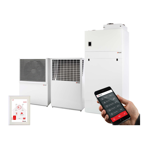
Unit type Product description Compact P AIR is a ventilation unit with heat recovery, that has a built-in heat pump, which is used for the production of domestic hot water, and which is also able to heat and cool the home by central heating via ventilation, and an energy-efficient and low-noise AIR air/water heat pump heats the home via floor heating or low-temperature radiators. -
Page 8: Unit - The Indoor Unit
Unit - the indoor unit Compact P: AIR: 1. Duct connections 22. Safety valve and manometer for the central heating circuit 2. Front panel for filter changes 23. Buffer tank 50 litres 3. Control panel (HMI touch panel) 24. Filling tap and particle filter for the central heating circuit 4. -
Page 9: Unit - The Outdoor Unit
Unit - the outdoor unit Front: Closed and open Rear side: Closed and open Side: Open AIR outdoor unit: 28. Fan 29. Evaporator 30. Heat pump 31. Condensate drain with integral heating cable 32. Connections to/from the indoor unit (liquid) 33. -
Page 10: Overview Of Temperature Sensors
Overview of temperature sensors Temperature sensors in the unit Temperature sensor in AIR indoor unit Temperature sensors in the outdoor unit T1: Outdoor air T18: Buffer tank (supply flow) T16: Before condenser (to outdoor unit) T2: Supply air T17: After condenser (from outdoor unit) T4: Extract air after heat exchanger T20: Outdoor temperature T5: Condenser... -
Page 11: Dimensional Drawing
Dimensional drawing Indoor unit: Connections: 1. Outdoor air 2. Supply air 3. Extract air 4. Discharge air Weight indoor unit: 268 kg All measurements are indicated in mm. - Page 12 Outdoor unit AIR6 (2022): Alle mål i mm Seen from below Weight AIR6 outdoor unit: 145 kg The bottom seen from above Outdoor unit AIR9 (2022): Alle mål i mm Seen from below Weight AIR9 outdoor unit: 155 kg The bottom seen from above...
-
Page 13: Piping Diagram
10. Safety valve 2.5 bar 2. Shut-off valve 11. Circulation pump P1 (charging circuit) 130mm 3. Shut-off valve with particle filter 12. Circulation pump P2 central heating circuit (not Nilan supply) 4. Supplemental electric heating buffer tank 1x3kW & 13. Filling tap 1/2" 1x2kW 14. -
Page 14: Accessories
If you want to adjust the fan speed level in accordance with the level of use of the dwelling/building (amount of people), you can retrofit a CO2 sensor. Nilan’s CO sensors calibrate automatically. On the control panel, you select the CO2 level you want. If this level is exceeded, ventilation will automatically increase. -
Page 15: Extension Cable Hmi Control Panel
To make it esay to service the unit in the future, we recommend that you fit a flexible connection between the unit and the duct system. Nilan flexible sound damper absorbs sounds effectively from both the duct system and from roof stacks. -
Page 16: Pollen Filter
This should be placed in the outdoor air intake, which will reduce the pollen count in the dwelling. Trolley A Nilan trolley makes it easy to transport the heavy units into the home, without having to carry out heavy lifting yourself with the risk of injury. -
Page 17: Set-Up
The ventilation unit is delivered fully assembled and wrapped on a pallet. You can lift the unit from the pallet and transport it into the building by using a Nilan lifting dolly. You thereby avoid heavy lifting. The unit is delivered from the factory fitted with 4 lifting straps, one in each corner. -
Page 18: Mounting Outdoor Unit
Mounting outdoor unit Transport into the building outdoor unit The AIR outdoor unit is delivered wrapped in foil and fixed on a transport pallet with strapping bands. If the surface is suitable, we recommend that you use a lifting dolly to move the unit ATTENTION If you use a crane to lift in AIR, please be aware that the weight is not evenly distributed at the front and at the back. -
Page 19: Positioning An Outdoor Unit
Positioning an outdoor unit An outdoor unit must always be positioned on a firm, horizontal and vibration free surface. Consider securing it to a fixed base. You should also take into account the prevailing wind direction during the cold months when heating is required, as the performance of the heat pump will be reduced if the outdoor unit is exposed to strong winds. -
Page 20: Foundation
Foundation Adjustable legs Foundation Drain for condensate water Fascine Pipe for electrical connection min. 50mm 150 mm 150 mm The illustrations above show an example of an AIR outdoor unit. ATTENTION AIR should be placed on a stable surface or a poured foundation. Condensate drain During operation, condensate water will form in the evaporator of the outdoor unit. -
Page 21: Detaching The Front Doors From The Air Outdoor Unit
Detaching the front doors from the AIR outdoor unit If you need to access the mechanics, electronics or the plumbing connections in the AIR outdoor unit, you can detach the upper and lower metal plates at the front. WARNING Always disconnect the power supply to the unit before opening the doors to carry out e.g. installation, inspection, clean- ing or maintenance. -
Page 22: Electrical Installation
Electrical installation Safety ATTENTION All work must be carried out by qualified persons and in compliance with existing legislation and regulations. ATTENTION It is important that the power is off, if you do work to the electrical components of the unit. It is important to check that wires are not damaged or squeezed during connection and use. -
Page 23: Electrical Connection Unit
Electrical connection unit Power supply CAUTION The power supply is plugged into a 230V socket with a safety switch. It is important that the unit has earth connection. The ventilation unit is supplied with an EU Schuko plug for 230V power supply. -
Page 24: Change From 400V To 230V
Change from 400V to 230V The standard connection in the unit is 3x400V + N + PE. In those countries or areas where this standard is not applicable, the unit can easily be switched to either 3x230V + N + PE or 1x230V+ N + PE. The terminal block can be found in the control system for AIR. -
Page 25: Circulation Pump
Circulation pump In Compact P AIR and Compact P GEO, there is a Power supply cable for circulation pump for central circuit in the Electrical connection panel. The cable is marked with a sticker with the text "Circulation pump" and ends in 3 screw terminals. Compact P AIR Power supply cable for circulation pump for Compact P GEO... -
Page 26: Connecting A Gateway
Connecting to the internet Using an RJ45 cable, you connect the gateway to a router with internet connection (cable not supplied by Nilan). Once the gateway is connected to a power supply and connection to the router has been established, you will have a secure cloud con- nection. -
Page 27: Hmi Control Panel
The panel is moved out of the unit and the wires are routed through the wire bushing and connected to the terminal block, as shown below. Nilan offers a connection cable with RJ12 plugs of 15 m. It is also possible to customize a cable up to 50 m in length. A standard LAN cable is used for this. -
Page 28: Electrical Connection Accessories
Electrical connection accessories SHW hot water tank The SHW hot water tank is connected to Compact P2 AIR connection panel as shown below. The SHW tank has its own power supply via a Schuko plug. 1. RJ45 plug for transmitting top temperature (T21), bottom temperature (T22) and anode monitoring in the SHW tank. -
Page 29: User Selection 1
User selection 1 User selection 1 is connected via the 8-pin plug mounted on top of the unit. The user selection functions are used to override normal operation. The input signal must come from a potential-free switch. When closed, the function is activated with the settings selected in the control panel under Service / User selection. Some examples of the situations in which the user selection functions are used: Cooker hood If you choose to run the cooker hood over the ventilation unit, the cooker hood sends a potential-free signal to the... -
Page 30: External Electrical Pre-Heating Element
External electrical pre-heating element It is possible to purchase an external electrical pre-heating element for frost protection of the ventilation unit. The electrical pre-heating element is mounted in the outdoor air duct before the unit with the necessary temperature sensor. If it is desired to see the actual outdoor air temperature on the control panel, the temperature sensor T1 / T8 must be led out into the duct before the pre-heating element. -
Page 31: Co2 Sensor
sensor If there is a large load change in the home / building, it is advantageous to install a CO sensor to control the air exchange. The CO sensor measures the CO level in the exhaust air, and regulates the ventilation level accordingly. The CO sensor is mounted in the unit as illustrated below: 1. - Page 32 7. Mount the power supply box in the box for automatic. 8. Connects as shown in the electrical diagram below. (pre-drill 2 holes for the screws). 9. Reinstall the counterflow heat exchanger. Remember to reinstall the T4 sensor. For SW version 2.00x or less, the resistor must be mounted in series with a black signal cable For SW version 2.01x and above, do not mount a resistor.
-
Page 33: Installation Of Expansion Pcb On Cts602 Circuit Board
5. Connect the wires up in accordance with the wiring diagram. ATTENTION The expansion PCB and the connections must be installed by a certified electrician. The expansion PCB is an accessory for the CTS602 circuit board. Nilan does not supply external components. -
Page 34: User Selection 2
User selection 2 With User selection 2, the same options are achieved as with User selection 1. In addition, you get the option of a relay output that can control e.g. a damper or whatever need one may have to control an external function. User selection 2 potential-free input is connected to TF13 and User selection 2 output is connected to relay R7 on the PCB board. -
Page 35: Em-Box (Damper Option)
EM-box (damper option) Dimensional drawing: If it is desired to run the cooker hood over the ventilation system, it may in some cases be difficult to get enough air for the cooker hood. With an EM box installed and when the cooker hood is in operation, you can reg- ulate the extraction so that less air is extracted out of the other rooms, e.g. -
Page 36: Dtbu (Damper Option)
DTBU (damper option) If it is desired to run the cooker hood over the ventilation system, it may in some cases be difficult to get enough air for the cooker hood. To solve that challenge, an EM-box solution can be used. However, if there is not enough space in the installation for an EM box, you can alternatively connect a DTBU damper in the duct system, which has the same function, except that it does not have a built-in dirt filter. -
Page 37: Fire Thermostat / External Fire Automation System
Fire thermostat / external fire automation system The ventilation unit can be connected up to an external fire thermostat that will stop the ventilation unit in the event of fire. The same port can be used for con- nection of an external fire automation system. The control system identifies a broken input signal as fire, and stops. -
Page 38: External Heat Supply
External heat supply The unit can control an external heat supply, such as electric radiators or an underfloor heating system. This feature is used in the cases where the unit contributes to the heating of the house via a heat pump and/or a after-heating element. -
Page 39: Active Cooling Function
Active cooling function The AIR unit has a reversible cold circuit, which means that it can be used to actively cool the home, using either the floor heating sys- tem or fan coils. CAUTION If it is wished to operate with cooling, it is important to use glycol in the brine circuit to avoid icing in the heat pump. Active cooling using the floor heating There is an external temperature sensor connected to digital input D3. -
Page 40: Plumbing Installation
Plumbing installation Condensate drain Important information Compact P is supplied with a reinforced 20 mm condensate drain tube with an integral water trap. ATTENTION Run the condensate drain tube to the nearest drain, allowing an even fall of at least 1 cm per m. The overflow from the safety valve for domestic cold water must likewise be led to a clearly visible drain. -
Page 41: Hot Water Tank
All work must be performed by qualified personnel and in accordance with relevant legislation and regulations. Nilan's hot water tanks are double-enamelled, ensuring long life. The efficient foam insulation protects against unnecessary heat loss. All connection nozzles for water have 3/4" thread and are located in the tank bottom. -
Page 42: Requirements To Quality Of Water
Requirements to quality of water The hot water tank in the Nilan units is made of steel, which has been given a double enamelling, to ensure an extra long service life. In addition, the tank is equipped with a sacrificial anode as extra protection. It is important that the sacrificial anode is replaced regularly. -
Page 43: Central Heating
Central heating Water connection overview, indoor unit 1. Supply flow to central heating, 3/4" 2. Return flow from central heating, 3/4" 3. Supply flow from outdoor unit (hot), 1" 4. Return flow to outdoor unit (cold), 1" 5. Circulation pump between outdoor unit and indoor unit 6. -
Page 44: Connections Overview Outdoor Unit
Connections overview outdoor unit AIR outdoor unit rear side: AIR6 and AIR9 outdoor unit seen from below: 10. Supply flow to indoor unit (hot), fitted with a flexible hose (AIR6: 3/4” , AIR9: 1”) 11. Return flow from indoor unit (cold), fitted with a flexible hose (AIR6: 3/4” , AIR9: 1”) 12. -
Page 45: Mounting Hoses To The Outdoor Unit
Mounting hoses to the outdoor unit You can mount hoses to the outdoor unit in different ways. Your decision will depend on the available space, and whether you want to be able to access the outdoor unit from the bottom or from the back. 1a. -
Page 46: Insulation Of Hoses From The Outdoor Unit
Insulation of hoses from the outdoor unit It is important that the brine hoses between the indoor part and the outdoor part are properly insulated. This is done to avoid heat loss and to achieve good operation. CAUTION If the brine hoses is not well insulated, the AIR heat pump will use significantly more energy and in worst case, there will not be enough heat in the house. -
Page 47: Plumbing Connections Accessories
Plumbing connections accessories Safety group CAUTION Safety group must be installed in connection with hot water tanks. When water is heated to 60 °C, it expands by 2%. A pressured tank could burst without a safety valve keeping excess water out. The safety valve should therefore drip during warming up. -
Page 48: Hot Water Tank
Everything within the dashed line is Nilan delivery. 1. Connection (AIR6: 3/4” , AIR9: 1”) 12. Circulation pump P2 central heating circuit (not Nilan supply) 2. Shut-off valve 13. Electronically monitored sacrificial anode 5/4” 3. Shut-off valve with particle filter 14. -
Page 49: Connecting To Shw Hot Water
Connecting to SHW hot water The domestic cold water is pre-heated in the SHW tank up to 45 °C by the AIR heat pump (default setting 40 °C) through the domestic water coil. It is then fed to the DHW tank in the Compact P, where it is heated to the desired hot water temperature. Buffer tank DHW tank bottom SHW tank bottom... -
Page 50: Connection To Supplementary Coil In Shw Hot Water Tank
The SHW container is equipped as standard with a supplementary coil with a length of 8.5m. The supplementary coil can be connected to a solar panel with external solar heating control (not Nilan supply), or other heat source, which contributes to heating the domestic water. -
Page 51: Ventilation Installation
This is to avoid vibrations from the unit being transmitted to the duct system. It will also make it easier to move the unit, which may be necessary during future services of the unit. Nilan can supply Soundflex tubes that you can use as flexible connections between the ventilation unit and the duct system. They will also reduce sounds from the system considerably. -
Page 52: Extract Air
Extract air Install the extract air valves in high-humidity rooms and place them strategically where they can extract humid and vitiated air from the dwelling/building most efficiently. High-humidity rooms are, for example: • Bathroom • Lavatory • Kitchen • Utility room Supply air Install supply air valves in living areas. -
Page 53: Balancing
Balancing Important information ATTENTION To ensure the ventilation system operates optimally, it is important that it is balanced correctly. We recommend that ex- perts do this. It is important to measure the total supply air and the total extract air. The system must have a minimum vacuum, which means it draw out more air than it blows in. -
Page 54: Start-Up
Start-up Central heating Filling with water ATTENTION Before starting the heat pump and the circulation pump, the central heating circuit must be filled with water. Fill central heating circuit with water via the feed tap until the correct water pressure is obtained. It is important that all circuits in the central heating system are open during filling. -
Page 55: Troubleshooting
Troubleshooting Emergency mode Emergency mode domestic hot water If an error occurs in the control system or components in the Compact P, and the unit therefore stops, it will not be able to produce do- mestic hot water. If the installer is not able to come right away or the error happens outside the opening hours, and you therefore cannot contact the in- staller, there is a possibility to get hot water by setting the unit into emergency mode. -
Page 56: Emergency Mode Central Heating
Emergency mode central heating If an error occurs in the control system or components in the AIR air/water heat pump, and the heat pump therefore stops, it will not be able to heat up the house by the central heating. If the installer is not able to come right away or the error happens outside the opening hours, and you therefore cannot contact the in- staller, there is a possibility to heat up the house by setting the AIR heat pump into emergency mode. -
Page 57: Domestic Hot Water
Domestic hot water Errors and solutions domestic hot water Problem Possible cause Solution The unit produces insufficient domestic The filters may be blocked so that insuf- Change the filters and, if necessary, hot water. ficient air is reaching the unit. change the filter change period to a This can occur if the filters are not shorter Interval. - Page 60 25 St Leonards Road Horsham West Sussex RH13 6EH Tel: +44 (0) 14 03 56 30 45 service@slservicesgroup.com or info@slservicesgroup.com www.slservicesgroup.com Ireland: Nilan Ireland Ballylahive, Abbeydorney Tel: +353 (0) 87 97 98 361 maurice@nilan.ie www.nilanireland.ei Nilan A/S Nilanvej 2 8722 Hedensted Danmark Tlf.
Need help?
Do you have a question about the Compact P AIR6 and is the answer not in the manual?
Questions and answers