
Related Manuals for MEDICAL ILLUMINATION nuvo Navigator Lift 180 AirPlus-Single


Summary of Contents for MEDICAL ILLUMINATION nuvo Navigator Lift 180 AirPlus-Single
- Page 1 Installation Instructions Part 2 – Pendant system [en] ™ Plus ™ Plus ™ Navigator Lift 180 Air – Single, Navigator Lift 180 Air – Dual, Navigator Lift ™ Friction – Single, Navigator Lift 180 Friction – Dual...
- Page 2 Notes on Safe Installation Dear assembly operator, Please read these Installation Instructions very carefully, and in particular Chapter 2, “Safety Instructions“ which includes important safety information. Observe the safety in- structions and requirements set out in these Installation Instructions. Service technician •...
- Page 3 1568908, Edition 2019-06, Version 0...
-
Page 4: Table Of Contents
Table of Contents 1 Versions, Scope of Delivery and Installation References ™ Plus Overview of the pendant system Navigator Lift 180 Air – Single arm Plus Scope of delivery of the spring arm, Navigator Lift ™ 180 Air – Single arm Overview of the pendant system ™... - Page 5 Table of Contents 6 Mounting Threaded Bolts to the Interface Plate Mounting situation: Mounting the interface plate to the raw ceiling without intermediate ceiling 6.1.1 Cutting the threaded bolts to length 6.1.2 Mounting the threaded bolts 6.1.3 Mounting the upper insulations to the threaded bolts Mounting situation: Interface plate on the raw ceiling with intermediate ceiling 32 6.2.1 Cutting the threaded bolts to length 6.2.2 Mounting the threaded bolts to the interface plate Single / Dual...
- Page 6 Table of Contents 13 Inspections 13.1 Gas inspection 13.2 Mechanical Collision Test 14 Mounting the Canopy, Cover Caps, and Cover Panels 14.1 Mounting a Single / Dual canopy 14.1.1 Preparing the installation of the canopy 14.1.2 Mounting the canopy halves 14.2 Mounting the Single canopy 14.2.1 Preparing the installation of the canopy...
- Page 7 Table of Contents 16 Initial and Repeated Commissioning and Handover 17 Technical Description 18 Technical Data 19 Electromagnetic Compatibility (EMC) Information 19.1 Guidelines and manufacturer’s declarations 19.1.1 Electromagnetic emissions 19.1.2 Electromagnetic immunity 19.1.3 Test specifications 20 Approved Nuvo Products 21 Optional Accessories 22 Possible Combination with Third-Party Products Notes 1568908, Edition 2019-06, Version 0...
-
Page 8: Versions, Scope Of Delivery And Installation References
Versions, Scope of Delivery and Installation References Plus Overview of the pendant system Navigator Lift 180 Air Figure 1: Scope of delivery of the spring arm, ™ – Single arm ™ Plus Navigator Lift 180 Air – Single arm 340° 340°... -
Page 9: Scope Of Delivery Of The Spring Arm, Navigator Lift ™ 180 Air Plus - Single Arm
Versions, Scope of Delivery and Installation References See “Figure 1: on Page 8” Interface plate (Single / Dual) – pre-assembled Intermediate ceiling – installed by the customer on site Scope of delivery of the spring arm, Navigator Lift 180 Air- ™... -
Page 10: Overview Of The Pendant System
Versions, Scope of Delivery and Installation References Overview of the pendant system Figure 2: Scope of delivery of the extension Plus Navigator Lift ™ 180 Air – Dual arm arm with spring arm, ™ Plus Navigator Lift 180 Air – Dual arm 340°... -
Page 11: Scope Of Delivery Of The Extension Arm With Spring Arm
Versions, Scope of Delivery and Installation References See “Figure 2: on Page 10” Interface plate (Single / Dual) – pre-assembled Intermediate ceiling – installed by the customer on site Scope of delivery of the extension arm with spring arm, Plus Navigator Lift ™... -
Page 12: Overview Of The Pendant System
Versions, Scope of Delivery and Installation References Overview of the pendant system Figure 3: Scope of delivery of the spring arm, Navigator Lift ™ 180 Friction – Single arm ™ Navigator Lift 180 Friction – Single arm 340° 340° 340° 340°... -
Page 13: Scope Of Delivery Of The Spring Arm, Navigator Lift
Versions, Scope of Delivery and Installation References See “Figure 3: on Page 12” Interface plate (Single / Dual) – pre-assembled Intermediate ceiling – installed by the customer on site Scope of delivery of the spring arm, Navigator Lift ™ 180 Friction – Single arm The scope of delivery can vary depending on the individual order. -
Page 14: Overview Of The Pendant System
Versions, Scope of Delivery and Installation References Overview of the pendant system Figure 4: Scope of delivery of the extension Navigator Lift ™ 180 Friction – Dual arm arm with spring arm, ™ Navigator Lift 180 Friction – Dual arm 340°... -
Page 15: Scope Of Delivery Of The Extension Arm With Spring Arm
Versions, Scope of Delivery and Installation References See “Figure 4: on Page 14” Interface plate (Single / Dual) – pre-assembled Intermediate ceiling – installed by the customer on site Scope of delivery of the extension arm with spring arm, Navigator Lift ™... -
Page 16: Overview Of Optional Accessories
Versions, Scope of Delivery and Installation References Overview of optional accessories Figure 5: Scope of delivery of optional acces- sories ™ Plus ™ The Figure illustrates the pendant system Navigator Lift 180 Air . The optional accessories for the pendant system Navigator Lift Friction are identical. -
Page 17: Scope Of Delivery Of Optional Accessories
Versions, Scope of Delivery and Installation References See “Figure 5: on Page 16” Upon delivery of the system from the factory the following optional accessories are al- ready assembled: 1.10 Scope of delivery of optional accessories Indirect extension arm lighting (extension arm lengths 1000, 1200, 1400, or 1600 mm) For a retrofit: Installation as described in Chapter 10, on Page 49 –... -
Page 18: Safety Instructions
Safety Instructions Approved Nuvo products The following Nuvo products are approved for use on the pendant system: • Nuvo products as described in Chapter 20, “Approved Nuvo Products”, on Page 97 Combination with products of other manufacturers Read the Installation Instructions •... -
Page 19: Supplementary Symbols Used In The Safety Instructions
Safety Instructions Supplementary symbols used in the safety instructions Explosion hazard: warns of the improper use of oxygen (see Chapter 2.11, “Proper use of oxygen”, on Page 24). Danger of fire: warns of the improper use of oxygen (see Chapter 2.11, “Proper use of oxygen”, on Page 24). -
Page 20: Description Of Graphic Symbols Possibly Used On The Device And The Package
Safety Instructions Description of graphic symbols possibly used on the device and the package WARNING SIGN: warns that the spring arm may jump up suddenly. Personenschäden: Endgerät oder Adaption nicht abnehmen, bevor der Federarm in der Horizontalen (0 Grad Position) eingestellt und fixiert ist. Personal injury: Do not remove the end device or adaption before the spring arm has been properly adjusted and fixed in its horizontal (0 degree) position. -
Page 21: Intended Purpose
Safety Instructions Atmospheric pressure: indicates the permissible atmospheric pressure values in a range from 500 hPa to 1060 hPa for transport and storage. Relative humidity: indicates the permissible humidity values in a range from 10% to 75% for transport and storage. Ambient temperature: indicates the permissible ambient temperature values in a range from -25°C to 70°C for transport and storage. -
Page 22: Ambient Conditions
The rating plate indicates the serial number (SN) of the pendant sys- load 120-18 0 kg tem. Manufactured for Medical Illumination International, 547 Library Street, San Fernando, CA 91340 USA Power supply • The rating plate provides information on the power supply of the pen- TYPE: Navigator Lift, 0,AirPlus,... -
Page 23: Retrofit To An Already Installed Ceiling Mount
Safety Instructions Retrofit to an already installed ceiling mount WARNING Risk of the ceiling mount dropping In the case of retrofits to an already installed ceiling mount the fixing ele- ments used must be inspected by a structural analyst and approved for the new pendant system: •... -
Page 24: Proper Use Of Oxygen
Safety Instructions WARNING Sudden release of the spring arm Warns of the spring arm suddenly jumping up whilst dismantling the end devices from the Navigator M6 or whilst dismantling the adaption device, such as the Navigator M6, from the spring arm: •... -
Page 25: Warranty
Safety Instructions 2.12 Warranty WARNING Pendant system dropping The pendant system and the Navigator M6 are an adapted system with re- gard to the maximum load bearing capacity and maximum loading capaci- ty (payload). Alterations to the pendant system can result in exceeding the permissible, total or maximum loading capacity of the individual compo- nents. -
Page 26: Further Applicable Installation Instructions
Further Applicable Installation Instructions Figure 7: Overview of the structure of these Installation The Installation Instructions for the entire pendant system consist of sep- Instructions arate documents. For this reason, these Installation Instructions are only valid and complete if all the documents are available at the place of in- stallation. -
Page 27: Installation Equipment Required
Installation Equipment Required • Lifting device or forklift with a permitted payload of at least 250kg Alternatively, a hoisting winch with a permissible payload of at least 250kg can be used if space is lim- ited: – Check that the pendant system is sufficiently secured before lifting it. –... -
Page 28: Load Data
Load Data Plus Load data of the Navigator Lift 180 Air ™ Figure 8: Load data of the Navigator Lift ™ 180 Air Plus Version 5.1.1 Load data of the Single version (See Figure 8) The data required for calculating the ceiling load is indicated in the table below. -
Page 29: Load Data Of The Navigator Lift ™ 180 Friction
Load Data Load data of the Navigator Lift ™ 180 Friction ™ Figure 10: Load data of the Navigator Lift 180 Friction Version 5.2.1 Load data of the Single version (See Figure 10) The data required for calculating the ceiling load is indicated in the table below. -
Page 30: Mounting Threaded Bolts To The Interface Plate
Mounting Threaded Bolts to the Interface Plate Mounting situation: Mounting the interface plate Figure 12: Cutting and installing the threaded bolts for the Sin- to the raw ceiling without intermediate ceiling gle / Dual interface plate on the raw ceiling 6.1.1 Cutting the threaded bolts to length Single (See Figure 12) -
Page 31: Mounting The Upper Insulations To The Threaded Bolts
Mounting Threaded Bolts to the Interface Plate 6.1.3 Mounting the upper insulations to the threaded bolts Figure 13: Mounting the upper insulations to the threaded bolts (See Figure 13) Single The 6 (Single version) or 12 (Dual version) hexagonal nuts M16② must be mounted to the threaded bolts M16①... -
Page 32: Mounting Situation: Interface Plate On The Raw Ceiling With Intermediate Ceiling
Mounting Threaded Bolts to the Interface Plate Mounting situation: Interface plate on the raw Figure 14: Cutting the threaded bolts for the Single / Dual inter- ceiling with intermediate ceiling face plate on the raw ceiling to length 6.2.1 Cutting the threaded bolts to length Single (See Figure 14) If a Single / Dual interface plate... -
Page 33: Mounting The Threaded Bolts To The Interface Plate Single / Dual
Mounting Threaded Bolts to the Interface Plate 6.2.2 Mounting the threaded bolts to the interface plate Single / Figure 15: Mounting the upper insulations to the threaded Dual bolts (See Figure 15) Single Screw 1 hexagonal nut M16② each onto the 6/12 threaded bolts M16③... -
Page 34: Mounting The Upper Insulations To The Threaded Bolts
Mounting Threaded Bolts to the Interface Plate 6.2.3 Mounting the upper insulations to the threaded bolts Figure 16: Mounting the upper insulations to the threaded bolts (See Figure 16) Single Single For each threaded bolt M16① screw a hexagonal nut M16② onto the threaded bolts M16①... -
Page 35: Mounting Situation: Interface Plate On The Intermediate Ceiling Mount
Mounting Threaded Bolts to the Interface Plate Mounting situation: Interface plate on the inter- Figure 17: Mounting the threaded bolts mediate ceiling mount Single 6.3.1 Mounting the threaded bolts (See Figure 17) The 6 (Single version) or 12 (Dual version) threaded bolts M16 x 330mm③... -
Page 36: Mounting The Upper Insulations To The Threaded Bolts
Mounting Threaded Bolts to the Interface Plate 6.3.2 Mounting the upper insulations to the threaded bolts Figure 18: Mounting the upper insulations to the threaded bolts (See Figure 18) Single The 6 (Single version) or 12 (Dual version) hexagonal nuts M16② must be mounted to the threaded bolts M16 x 330mm①... -
Page 37: Pre-Assembly: Mounting An Extended Ceiling Tube
Pre-Assembly: Mounting an Extended Ceiling Tube Components described in this chapter Figure 19: Components described in this chapter (See Figure 19) • The ceiling tube illustrated in the Figure is mounted to the spring or the extension arm with spring arm •... -
Page 38: Mounting An Extended Ceiling Tube
Pre-Assembly: Mounting an Extended Ceiling Tube Mounting an extended ceiling tube Figure 20: Mounting the ceiling tube 7.2.1 Mounting the ceiling tube (See Figure 20) The Figure shows a simplified representation with only the spring arm or the extension arm with spring arm without pre-assembled cables. -
Page 39: Mounting The Strain Relieving Mechanism In The Ceiling Tube
Pre-Assembly: Mounting an Extended Ceiling Tube 7.2.2 Mounting the strain relieving mechanism in the ceiling Figure 21: Mounting the strain relieving mechanism in the ceil- tube ing tube (See Figure 21) The Figure shows a simplified representation with only the spring arm or the extension arm with spring arm without pre-assembled cables. -
Page 40: Subsequently Mounting The Earthing Cable To The Ceiling Tube
Pre-Assembly: Mounting an Extended Ceiling Tube 7.2.3 Subsequently mounting the earthing cable to the ceiling Figure 22: Subsequently mounting the earthing cable to the tube ceiling tube (See Figure 22) The system is delivered with the earthing cable pre-assembled! Fit 1 lock washer S4②/④ each above and below the ring cable lug③... -
Page 41: Mounting The Ceiling Tube To The Threaded Bolts Of The Interface Plate
Mounting the Ceiling Tube to the Threaded Bolts of the Interface Plate Components described in this chapter Figure 23: Components described in this chapter (See Figure 23) • The spring arm or the extension arm with spring arm illustrated in the Figure is mounted to the threaded bolts of the interface plate •... -
Page 42: Mounting The Ceiling Tube
Mounting the Ceiling Tube to the Threaded Bolts of the Interface Plate Mounting the ceiling tube Figure 24: Mounting the ceiling tube (See Figure 24) Single The Figure only shows a simplified representation of the flange⑥ with ceiling tube to be mounted to the threaded bolts. Further components pre-assembled to the flange⑥... -
Page 43: Aligning The Spring Arm / Extension Arm With The Interface Plate, Single
Mounting the Ceiling Tube to the Threaded Bolts of the Interface Plate Aligning the spring arm / extension arm with the Figure 25: Aligning the spring arm / extension arm with the interface plate, Single interface plate, Single (See Figure 25) Single The Figure only shows a simplified representation of the flange③... - Page 44 Mounting the Ceiling Tube to the Threaded Bolts of the Interface Plate Figure 26: Checking the horizontal alignment of the spring arm Check the horizontal alignment of the spring arm / extension arm / extension arm (see “Figure 26: on Page 44”): •...
-
Page 45: Aligning The Spring Arm / Extension Arm With The Interface Plate, Dual
Mounting the Ceiling Tube to the Threaded Bolts of the Interface Plate Aligning the spring arm / extension arm with the Figure 27: Aligning the spring arm / extension arm with the interface plate, Dual interface plate, Dual (See Figure 27) The Figure only shows a simplified representation of the flange③... - Page 46 Mounting the Ceiling Tube to the Threaded Bolts of the Interface Plate Figure 28: Checking the horizontal alignment of the spring arm Check the horizontal alignment of the spring arm / extension arm / extension arm (see “Figure 28: on Page 46”): •...
-
Page 47: Mounting The Drop Tube To The Spring Arm
Mounting the Drop tube to the Spring Arm Components described in this chapter Figure 29: Components described in this chapter (See Figure 29) • The Drop tube with Bearing Unit Friction (slide bearing) illustrated in the Figure is mounted onto the spring arm or extension arm with spring arm •... -
Page 48: Mounting The Drop Tube To The Spring Arm
Mounting the Drop tube to the Spring Arm Mounting the Drop tube to the spring arm Figure 30: Mounting the Drop tube to the spring arm (See Figure 30) Place the Drop tube under the spring arm or the extension arm with spring arm such that the end stop②... -
Page 49: Mounting The Extension Arm Lighting (For Retrofit Only)
Mounting the Extension Arm Lighting (for Retrofit only) Figure 31: Mounting the extension arm lighting (See Figure 31) The Figure illustrates the extension arm with spring arm of the Navi- Plus gator Lift ™ 180 Air system. The steps required for installing the pen- dant system Navigator Lift ™... -
Page 50: Mounting Cables
Mounting Cables 11.1 Safety instructions WARNING Electric shock hazard Power cables may have been laid in the pendant system. Contact with en- ergized components presents a danger to life from electric shock. Motor-driven, mobile device components can cause injury in the case of being switched on unintentionally. -
Page 51: Connecting Cables To The Extension Arm With Spring Arm, Dual Arm, With Navigator M6
Mounting Cables 11.2 Connecting cables to the extension arm with spring arm, Du- al arm, with Navigator M6 The power cables, pneumatic pipes, earthing and control cables, as well as the gas hoses are pre-installed in the Navigator M6 and must be routed through the pendant system. Observe the safety instructions in Chapter 11.1, on Page 50. - Page 52 Mounting Cables Figure 32: Routing the power cable 1568908, Edition 2019-06, Version 0...
-
Page 53: Routing And Connecting Pneumatic Brake Pipes
Mounting Cables 11.2.2 Routing and connecting pneumatic brake pipes (See "Figure 33“) Observe the safety instructions in Chapter 11.1, on Page 50. The pneumatic brake pipes① are pre-assembled in the pendant system and plugged onto the brake connecting points and . The brake pipes① are laid in a spiral coiled tube if required. - Page 54 Mounting Cables Figure 33: Routing and connecting pneumatic brake pipes 1568908, Edition 2019-06, Version 0...
-
Page 55: Connecting The Optional Extension Arm Lighting
Mounting Cables 11.3 Connecting the optional extension arm lighting (See "Figure 34“) Observe the safety instructions in Chapter 11.1, on Page 50. Insert the cable① (extension arm lighting) into the mounting aperture of the spring arm bearing support⑥ and lay it above the swivel axis (revolute joint)⑦ . Establish the assembly connection②... - Page 56 Mounting Cables Figure 34: Connecting the optional extension arm lighting Table 03: Cable assignment – extension arm with spring arm, Dual arm, with Navigator M6 – options No. in From Designation Length [mm] Remark Fig. 34 ① Extension arm Cable③ Integrated into the lighting extension arm lighting...
-
Page 57: Connecting The Earthing Cables To The Extension Arm With Spring Arm, Dual Arm, With Navigator M6
Mounting Cables 11.4 Connecting the earthing cables to the extension arm with spring arm, Dual arm, with Navigator M6 (See "Figure 35“) The earthing cables are pre-assembled in the extension arm and must be laid and con- nected in the direction of the arrow. Observe the safety instructions in Chapter 11.1, on Page 50. - Page 58 Mounting Cables Figure 35: Connecting the earthing cables to the extension arm with spring arm, Dual arm, Navigator M6 Figure 36: Routing the supply cables and hoses through the extension arm with spring arm, Dual arm, with Navigator M6 1568908, Edition 2019-06, Version 0...
-
Page 59: Connecting The Cables And Hoses To The Spring Arm, Single Arm, With Navigator M6
Mounting Cables 11.6 Connecting the cables and hoses to the spring arm, Single arm, with Navigator M6 The power cables, pneumatic pipes, earthing and control cables, as well as the gas hoses are pre-installed in the Navigator M6 and must be routed through the pendant system. Observe the safety instructions in Chapter 11.1, on Page 50. - Page 60 Mounting Cables Figure 37: Connecting the cables and hoses to the spring arm, Single arm, with Navigator M6 1568908, Edition 2019-06, Version 0...
-
Page 61: Routing And Connecting Pneumatic Brake Pipes
Mounting Cables 11.6.2 Routing and connecting pneumatic brake pipes (See "Figure 38“) Observe the safety instructions in Chapter 11.1, on Page 50. The pneumatic brake pipes① in the pendant system are pre-assembled and plugged onto brake connecting point . The brake pipes① are laid in a spiral coiled tube if required. NOTE –... - Page 62 Mounting Cables Figure 38: Routing and connecting pneumatic brake pipes 1568908, Edition 2019-06, Version 0...
-
Page 63: Connecting The Earthing Cables To The Spring Arm, Single Arm, With Navigator M6
Mounting Cables 11.7 Connecting the earthing cables to the spring arm, Single arm, with Navigator M6 (See "Figure 39“) The earthing cables are pre-assembled in the spring arm and must be laid and connected in the direction of the arrow. Observe the safety instructions in Chapter 11.1, on Page 50. - Page 64 Mounting Cables Figure 39: Connecting the earthing cables to the spring arm, Single arm, with Navigator M6 Figure 40: Routing the supply cables and hoses through the spring arm, Single arm, with Navigator M6 1568908, Edition 2019-06, Version 0...
-
Page 65: Connecting The Supply Cables
Connecting the Supply Cables 12.1 Safety Instructions WARNING Qualification of installation personnel The electrical connection of the pendant system and the Navigator M6 may only be performed by a qualified electrician: • Observe the safety instructions set out in the Installation Instructions Part 1 –... -
Page 66: Installing Gas Supply Hoses And Exhaust Air Ducts
Connecting the Supply Cables 12.2 Installing gas supply hoses and exhaust air Figure 41: Installing gas supply hoses and exhaust air ducts ducts (See Figure 41) Observe the safety instructions in Chapter 12.1, on Page 65. NOTE – Make sure that the gas types are correctly assigned •... -
Page 67: Connecting The Earthing Cables
Connecting the Supply Cables 12.3 Connecting the earthing cables Figure 42: Connecting the earthing cables (See Figure 42) The Figure shows a simplified illustration of the interface plate without extension arm and cables, etc. Observe the safety instructions in Chapter 12.1, on Page 65. Cut all green/yellow earthing cables (2.5mm²... -
Page 68: Inspections
Inspections 13.1 Gas inspection 1. Gas outlets and markings in accordance with DIN EN ISO 9170-1 or DIN EN ISO 9170-2 2. Leakage in accordance with DIN EN ISO 11197 3. Congestion in accordance with DIN EN ISO 7396-1 or DIN EN ISO 7396-2 4. -
Page 69: Mounting The Canopy, Cover Caps, And Cover Panels
Mounting the Canopy, Cover Caps, and Cover Panels 14.1 Mounting a Single / Dual canopy Figure 44: Preparing the installation of the canopy 14.1.1 Preparing the installation of the canopy (See Figure 44) The Figure shows a simplified illustration of the interface plate without ca- bles and without the extension arm or spring arm. -
Page 70: Mounting The Single Canopy
Mounting the Canopy, Cover Caps, and Cover Panels 14.2 Mounting the Single canopy Figure 46: Preparing the installation of the canopy 14.2.1 Preparing the installation of the canopy (See Figure 46) The Figure shows a simplified illustration of the interface plate without ca- bles and without the extension arm or spring arm. -
Page 71: Mounting/Dismantling The Cover Caps To/From The Extension Arm
Mounting the Canopy, Cover Caps, and Cover Panels 14.3 Mounting/dismantling the cover caps to/from the Figure 48: Mounting the cover caps extension arm 14.3.1 Mounting the cover caps (See Figure 48) The Figure shows a simplified representation with only the extension arm with spring arm without cables. -
Page 72: Mounting The Cover Plates To The Spring Arm
Mounting the Canopy, Cover Caps, and Cover Panels 14.4 Mounting the cover plates to the spring arm Figure 50: Mounting the cover plates to the spring arm (See Figure 50) The Figure shows the spring arm . The installation procedure for the extension arm with spring arm version is identical. -
Page 73: Mounting The Rear Side Panels To The Spring Arm
Mounting the Canopy, Cover Caps, and Cover Panels 14.5 Mounting the rear side panels to the spring arm Figure 51: Mounting the rear side panels to the spring arm (See Figure 51) The Figure shows the spring arm . The installation procedure for the extension arm with spring arm version is identical. -
Page 74: Mounting The Front Side Cover Panels To The Spring Arm
Mounting the Canopy, Cover Caps, and Cover Panels 14.7 Mounting the front side cover panels to the Figure 53: Mounting the front side cover panels to the spring spring arm (See Figure 53) The Figure shows the spring arm . The installation procedure for the extension arm with spring arm version is identical. -
Page 75: Adjustments
Adjustments 15.1 General safety instructions WARNING Electric shock hazard Electrical supply cables are laid in the pendant system. Contact with energized components presents a danger to life from electric shock. Disconnect the device from the mains before any adjustment work: •... -
Page 76: Adjusting The Brake On The Bearing Unit Friction
Adjustments 15.2.2 Adjusting the brake on the Bearing Unit Friction Figure 56: Adjusting the brake on the Bearing Unit Friction (Navigator Lift 180 Friction) ™ ™ (only Navigator Lift 180 Friction) (See Figure 56) ™ For the pendant system Navigator Lift 180 Friction, the mechanical brakes (friction brakes) keep the extension arm or spring arm in any adjusted posi- tion. -
Page 77: Adjusting The Brake On The Drop Tube Friction (Slide Bearing)
Adjustments 15.3 Adjusting the brake on the Drop tube Friction Figure 57: Adjusting the brake on the Drop tube (slide bearing) Friction (slide bearing) (See Figure 57) For all pendant system versions, the mechanical brake (friction brake) on the Drop tube keeps the adaption (e.g. the Navigator M6) in the adjusted position. -
Page 78: Adjusting The Load Bearing Capacity On The Spring Arm
Adjustments 15.5 Adjusting the load bearing capacity on the Figure 59: Opening the lower, rear cover panel spring arm (See Figure 59) The simplified representation illustrates the extension arm and spring arm without the cables mounted. The adjustment is identical for all ver- sions. -
Page 79: Adjusting The Load Bearing Capacity
Adjustments 15.5.2 Adjusting the load bearing capacity Figure 60: Adjusting the load bearing capacity and closing the lower, rear cover panel (See Figure 60) Tool to be used Use an Allen key (size 10) or a ring spanner (size 24). Unscrew the Allen cylinder screw M8 x 16mm③... -
Page 80: Adjusting The Vertical Lift On The Spring Arm
Adjustments 15.6 Adjusting the vertical lift on the spring arm Figure 61: Adjusting the vertical lift on the spring arm (See Figure 61) When replacing an end device (e.g. flat screen, medical device, etc.) the spring arm must be adjusted to the horizontal (0 degree position). 15.6.1 Opening the front, upper cover panel (See Figure 61) Follow the general safety instructions prescribed in Chapter 15.1, on... -
Page 81: Correcting The Vertical Alignment Of The Navigator M6
Adjustments 15.7 Correcting the vertical alignment of the Naviga- Figure 62: Correcting the vertical alignment of the Navigator tor M6 (See Figure 62) After mounting a end device (e.g. flat screen, medical device, etc.) there is a risk that the Navigator M6 is no longer in a precisely vertical position due to the weight of the end device. -
Page 82: Condition Of The Swivel Stop On The Extension Arm And Spring Arm As Supplied By Nuvo
Adjustments 15.8 Condition of the swivel stop on the extension Figure 63: Condition of the swivel stop on the extension arm arm and spring arm as supplied by Nuvo and spring arm as supplied by Nuvo ™ Plus The Figure illustrates the pendant system Navigator Lift 180 Air ™... -
Page 83: Adjusting The Swivel Stop On The Extension Arm, Spring Arm And Drop Tube
Adjustments 15.9 Adjusting the swivel stop on the extension arm, Figure 64: Adjusting the swivel stop on the extension arm, spring arm and Drop tube spring arm and Drop tube (See Figure 64) The swivel stops must be adjusted during installation independently of the system and application. -
Page 84: Stop Recommendation: Dual-Arm Pendant System With Bearing Unit Friction (Roller Bearing)
Adjustments 15.9.2 Stop recommendation: Dual-arm pendant system with Figure 65: Stop recommendation: Dual-arm pendant system Bearing Unit Friction (roller bearing) with Bearing Unit Friction (roller bearing) (See Figure 65) For all dual-arm pendant systems with a Bearing Unit Friction as interme- diate bearing , Nuvo recommends that you mount 2 ball stops ③... -
Page 85: Mounting The Swivel Stop
Adjustments 15.9.3 Mounting the swivel stop Figure 66: Mounting the swivel stop (See Figure 66) Follow the general safety instructions prescribed in Chapter 15.1, on Page 75. Unscrew a setscrew① from the threaded hole ② . Rotate the extension arm, spring arm or Drop tube towards the de- sired end stop position and then insert 1 ball stop③... -
Page 86: Changing Or Dismantling The Swivel Stop
Adjustments 15.9.4 Changing or dismantling the swivel stop Figure 67: Changing or dismantling the swivel stop (See Figure 67) Follow the general safety instructions prescribed in Chapter 15.1, on Page 75. Unscrew a setscrew① from the threaded hole ② . Rotate the extension arm, spring arm or Drop tube until the ball stop③... -
Page 87: Initial And Repeated Commissioning And Handover
Initial and Repeated Commissioning and Handover Initial commissioning The pendant system must be properly installed. Instructions for installation are in- cluded in the scope of delivery of the product. For commissioning following installation, proper initial commissioning must be car- ried out for the entire pendant system. Functional test Prior to using the pendant system and the Navigator M6 on a patient for the first time, a functional test must take place at the installation site. -
Page 88: Technical Description
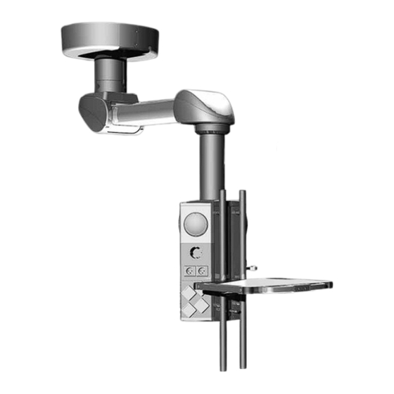
Technical Description Figure 68: Spring arm Navigator Lift ™ 180 Air Plus – Single / Navigator Lift ™ 180 Friction – Single-arm variant with Navigator M6 ™ Plus The Figure illustrates the extension arm with spring arm Navigator Lift 180 Air with Navigator M6 as an example. - Page 89 Technical Description ™ Plus ™ Figure 69: Extension arm with spring arm Navigator Lift 180 Air – Dual / Navigator Lift 180 Friction – Dual-arm variant with Navigator Plus The Figure illustrates the extension arm with spring arm Navigator Lift ™...
-
Page 90: Technical Data
Technical Data Modes of operation • The pendant systems Navigator Lift ™ 180 Air Plus – Single, Navigator Lift ™ 180 Air- Plus ™ ™ – Dual, Navigator Lift 180 Friction – Single and Navigator Lift 180 Friction – Dual are suitable for continuous operation. Rating plate •... - Page 91 Technical Data Brake torque Brake torque with the pneumatic brake actuated on the spring arm.... approx. 50Nm Brake torque with the pneumatic brake actuated on the extension arm and spring arm ........... approx. 50Nm / approx. 50Nm Manual forces Dynamic torque with the electromagnetic brake released depending on the position and payload ......................
-
Page 92: Electromagnetic Compatibility (Emc) Information
Electromagnetic Compatibility (EMC) Information 19.1 Guidelines and manufacturer’s declarations 19.1.1 Electromagnetic emissions The Navigator Lift ™ is intended for use in the ELECTROMAGNETIC ENVIRONMENT specified below. The customer or the user of the Navigator Lift ™ must ensure that it is used in such an environment. -
Page 93: Electromagnetic Immunity
Electromagnetic Compatibility (EMC) Information 19.1.2 Electromagnetic immunity The Navigator Lift ™ is intended for use in the ELECTROMAGNETIC environment speci- fied below. The customer or the user of the Navigator Lift ™ should ensure that it is used in such an environment. Interference immunity test Test level in accordance with IEC 60601 Test result... - Page 94 Electromagnetic Compatibility (EMC) Information Cont. The Navigator Lift ™ is intended for use in the ELECTROMAGNETIC environment speci- fied below. The customer or the user of the Navigator Lift ™ should ensure that it is used in such an environment. Interference immunity test Test level in accordance with IEC 60601 Compliance level...
-
Page 95: Test Specifications
Electromagnetic Compatibility (EMC) Information 19.1.3 Test specifications Test specifications for the INTERFERENCE IMMUNITY of ENCLOSURES against high- frequency wireless communication facilities Test frequency Frequency band Radio service Modulation Maximum Distance IMMUNITY TEST power LEVEL 380 to 390 TETRA 400 Pulse modulation 18Hz 430 to 470 GMRS 460,... - Page 96 Electromagnetic Compatibility (EMC) Information WARNING Do not operate this device immediately next to or together with other devices stacked on top of each other because this could result in improper operation. If operation in the described manner is unavoidable, this device and all other devices should be monitored in order to ensure proper opera- tion."...
-
Page 97: Approved Nuvo Products
Approved Nuvo Products Designation Navigator M6 and approved end devices in accordance with the current Operating Instructions of the Navigator M6 CEMOR and approved Nuvo products in accordance with the current Operating Instructions of the CEMOR. ™ 1946015 integration kit, MCS Slimline, Navigator Lift ™... -
Page 98: Notes
Notes 1568908, Edition 2019-06, Version 0... - Page 99 Notes 1568908, Edition 2019-06, Version 0...
Need help?
Do you have a question about the nuvo Navigator Lift 180 AirPlus-Single and is the answer not in the manual?
Questions and answers