Table of Contents
Advertisement
Quick Links
Advertisement
Table of Contents

Related Manuals for MEDICAL ILLUMINATION nuvo Navigator M6


Summary of Contents for MEDICAL ILLUMINATION nuvo Navigator M6
- Page 1 Installation Instructions Part 3 [EN] Navigator M6...
- Page 2 Notes on safe installation Dear assembly operator, please read these Installation Instructions very carefully, and in particular Chapter 2, “Sa- fety Instructions“ which includes important safety information. Observe the safety instruc- tions and requirements set out in these Installation Instructions. Service technician •...
- Page 3 How to contact us Nuvo Surgical • 1565 West 12th Street • Erie, PA 16501 • USA Phone: +1 (800) 663-1152 (USA and CANADA) Phone: +1 (814) 899-4220 (INTERNATIONAL) © Nuvo Surgical, 2019 1568916, Edition 2019-05, Version 0 Visit us on the Internet www.nuvosurgical.com E-mail address sales@nuvosurgical.com...
-
Page 4: Table Of Contents
Table of Contents 1 Configuration Examples, Scope of Delivery and Installation References 2 Safety Instructions Approved Nuvo products Combination with products of other manufacturers Structure of the safety instructions 2.3.1 Warnings of risk of injury 2.3.2 Warnings of damage to property 2.3.3 Indication of additional information Supplementary symbols used in the safety instructions Graphic symbols on the device and/or on the packaging... - Page 5 8 Installing the Shelf onto the Multi-Function Rack (MFR) Components described in this chapter Installing the shelf 8.2.1 Dismantling the holding clamp from the shelf 8.2.2 Positioning the shelf 8.2.3 Tightening the screws on the shelf 8.2.4 Connecting the cables of the electromagnetic brakes to the operating shelf 8.2.5 Connecting the pneumatic brake pipes to the operating shelf 9 Mounting the Sound System Components...
-
Page 6: Configuration Examples, Scope Of Delivery And Installation References
Configuration Examples, Scope of Delivery and Installation References Configuration examples The Navigator M6 in various equipment versions is combined with different Nuvo pendant systems depending on the medical discipline and individual space requirements. SpacePort ® Navigator ™ Navigator Lift ™ 150 / Navigator Lift ™... - Page 7 Configuration Examples, Scope of Delivery and Installation References Installation as described in Navigator M6 (Standard or XL size) Chapter 6 on Page 20 – Navigator M6 (length as specified in the order) with: – D-SUB plug connector for connecting the operating shelf for controlling a pendant system equipped with electromagnetic brakes –...
-
Page 8: Safety Instructions
Safety Instructions Approved Nuvo products Approved Nuvo products The following Nuvo products are approved for installation on the Navigator M6: • Chapter 16, “Approved Nuvo Products”, on Page 43, • Chapter 17, “Approved Third-Party Products”, on Page 43. Combination with products of other manufacturers Read the Installation Instructions for •... -
Page 9: Supplementary Symbols Used In The Safety Instructions
Safety Instructions Supplementary symbols used in the safety instructions Explosion hazard: warns of the improper use of oxygen (see Chapter 2.8.2 on Page 13). Danger of fire: warns of the improper use of oxygen (see Chapter 2.8.2 on Page 13). Electric shock hazard: warns of electric shock which can lead to severe injury or even death. -
Page 10: Graphic Symbols On The Device And/Or On The Packaging
Safety Instructions Graphic symbols on the device and/or on the packaging Read the Installation Instructions: Read these Installation Instructions carefully prior to in- stallation of the Navigator M6. This ensures that you benefit from all the advantages of the Navigator M6 and prevents any risk of injury or material damage. Observe the maximum load bearing capacity or maximum loading capacity (payload): warns of the risk of the Navigator M6 suddenly dropping because the maximum load bear- ing capacity or maximum loading capacity (payload) has been exceeded. -
Page 11: Intended Purpose
Safety Instructions Atmospheric pressure: indicates the permissible atmospheric pressure values in a range from 500hPa to 1060hPa for transport and storage. Relative humidity: indicates the permissible humidity values in a range from 10% to 75% for transport and storage. Ambient temperature: indicates the permissible ambient temperature values in a range from -25°C to 60°C for transport and storage. -
Page 12: Contraindications
Safety Instructions 2.6.2 Contraindications • The Navigator M6 must not be used close to strong magnetic fields. • No BF or CF application parts in accordance with IEC 60601-1 may be directly con- nected to the Navigator M6. Ambient conditions 2.7.1 Ambient conditions for storage and transport The following conditions apply to storage: •... -
Page 13: Proper Use Of Oxygen
Safety Instructions WARNING Electric shock hazard To prevent the risk of electric shock, the pendant system and the Naviga- tor M6 may only be connected to a supply network equipped with a protec- tive conductor: • The pendant system and the Navigator M6 must be connected in such a way that they can be disconnected from the mains at all poles and at the same time. -
Page 14: Ventilation At The Bottom Of The Navigator M6
Safety Instructions 2.8.3 Ventilation at the bottom of the Navigator M6 DANGER Danger of fire Escaping oxygen is combustible: If the air vents at the bottom of the Navigator M6 are covered, there is a risk of oxygen enrichment in the Nav- igator M6 in case of failure of optional oxygen hoses: •... -
Page 15: Electromagnetic Interference
Safety Instructions 2.10 Electromagnetic interference Medical electrical devices are subject to special precautionary measures with regard to electromagnetic compatibility (EMC) and must be installed and put into operation in accor- dance with the instructions below. The instructions in Chapter 15, “Electromagnetic Compatibility (EMC) Information”, on Page 38 must also be observed. -
Page 16: Electromagnetic Discharge
Safety Instructions 2.11 Electromagnetic discharge NOTICE Do not touch plugs Do not touch the pins of plugs marked with the ESD symbol with your fin- gers or handheld tools. Electrostatic discharge can cause the operator to suffer an electric shock or damage or even destroy microelectrical compo- nents. -
Page 17: Further Applicable Installation Instructions
Further Applicable Installation Instructions Figure 1: Overview of the structure of these Installation The Installation Instructions for the entire pendant system consist of sep- Instructions arate documents. For this reason, these Installation Instructions are only valid and complete if all the documents are available at the place of in- stallation. -
Page 18: Installation Equipment Required
2019 If the Navigator M6 is installed to a different pendant sys- Manufactured for Medical Illumination International , 547 Library Street, San Fernando, CA 91340 USA tem, there is a risk that the pendant system may drop: • Install the Navigator M6 to the specific pendant sys- tem for which it is intended as described in the Instal- lation Instructions included in the scope of delivery. -
Page 19: Label Indicating The Maximum Loading Capacity (Payload) Of The Navigator M6
15. Manufactured for – The following two digits indicate the year of manufacture, e.g. Medical Illumination International, 547 Library Street, San Fernando, CA 91340 USA 14 = 2014. – The letter in the 5 position indicates the factory, e.g. H = Hünfeld. -
Page 20: Mounting The Navigator M6 To The Drop Tube
Mounting the Navigator M6 to the Drop tube Components described in this chapter Figure 5: Components described in this chapter (See "Figure 5") The Figure shows a simplified illustration of the Navigator M6 without pre-assembled cables. • The Navigator M6 is mounted onto the Drop tube①... -
Page 21: Assignment Of The Threaded Bolts To The Pendant System
Mounting the Navigator M6 to the Drop tube 6.2.2 Assignment of the threaded bolts to the pendant system Figure 7: Assignment of the threaded bolts to the pendant system (See "Figure 7") The Navigator M6 has 4 threaded bolts each with M8 and M10 thread di- ameters. -
Page 22: Positioning The Navigator M6 Under The Drop Tube And Routing The Cables Through The Pendant System
Mounting the Navigator M6 to the Drop tube 6.2.4 Positioning the Navigator M6 under the Drop tube and Figure 9: Positioning the Navigator M6 under the Drop tube routing the cables through the pendant system and routing the cables into the pendant system (See "Figure 9") The Figure shows a simplified illustration of the Navigator M6 without pre- assembled cables. -
Page 23: Screwing The Navigator M6 To The Drop Tube
Mounting the Navigator M6 to the Drop tube 6.2.5 Screwing the Navigator M6 to the Drop tube Figure 10: Screwing the Navigator M6 onto the Drop tube (See "Figure 10") The Drop tube illustrated in the Figure has a specific geometry adapted to a special pendant system and may differ from the geometry of your Drop tube. -
Page 24: Determining And Checking The Maximum Loading Capacity (Payload)
Determining and Checking the Maximum Loading Capacity (Payload) What is the maximum loading capacity (pay- Figure 11: What is the maximum loading capacity (payload)? load)? (See "Figure 11") The maximum loading capacity (payload) corresponds to the total weight of all end devices, accessories, etc. which you have fixedly attached or placed onto the Navigator M6 (e.g.: operating shelf, shelf, flat screen, in- fusions, etc.). -
Page 25: Checking The Maximum Loading Capacity (Payload)
Determining and Checking the Maximum Loading Capacity (Payload) Checking the maximum loading capacity (pay- Figure 13: Checking the maximum loading capacity (payload) load) (See "Figure 13") The Figure shows the example of the Navigator M6 with a pre-assembled Multi-Function Rack (MFR). The label①... -
Page 26: Installing The Shelf Onto The Multi-Function Rack (Mfr)
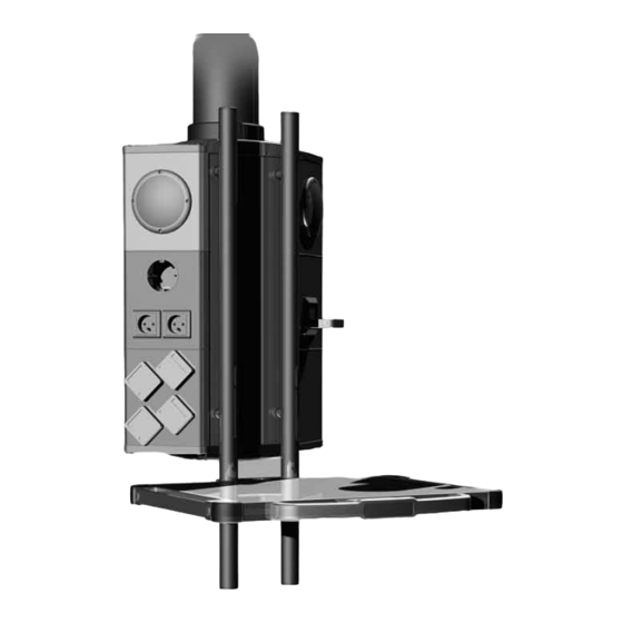
Installing the Shelf onto the Multi-Function Rack (MFR) Components described in this chapter Figure 14: Components described in this chapter (See "Figure 14") The operating shelf illustrated in the Figure is mounted onto the op- tional Multi-Function Rack (MFR). The steps required for the installation of the operating shelf and the standard shelf are identical. -
Page 27: Tightening The Screws On The Shelf
Installing the Shelf onto the Multi-Function Rack (MFR) 8.2.3 Tightening the screws on the shelf Figure 17: Tightening the screws on the shelf (See "Figure 17") Slightly screw on the holding clamp① from the bottom of the shelf using 2 Allen cylinder screws M8 x 50mm② – 8.8 – DIN 912. •... -
Page 28: Mounting The Sound System Components
Mounting the Sound System Components Mounting the docking station for external digital Figure 20: Mounting the docking station for external digital media players media players (See "Figure 20") The docking station is available in 2 versions: MediSound-System Bluetooth MediSound-System Interface The installation steps are identical for both versions. -
Page 29: Mounting The Ceiling Loudspeaker
Mounting the Sound System Components Mounting the ceiling loudspeaker Figure 21: Mounting the ceiling loudspeaker (See "Figure 21") The ceiling loudspeaker⑬ weighs approx. 4.5kg. Due to the different ceiling structures at the place of installation, no binding Installation In- structions can be provided. ... -
Page 30: Marking The Braking Points On The Pendant System
Marking the Braking Points on the Pendant System Figure 22: Marking the braking points on the pendant system (See "Figure 22") The braking points must be marked on the pendant systems OndaS- cope ® 400 / OndaScope ® 600 and Multi-Movement Pendant MMP 90 / MMP 200. -
Page 31: Inspections
Inspections 11.1 Electrical safety test For start-up following installation, proper initial commissioning of the entire pendant sys- tem with the Navigator M6 must be carried out e.g. based on the test standard for medical electrical equipment EN 62353. 11.2 Gas inspection Gas outlets and marking in accordance with DIN EN ISO 9170-1 or DIN EN ISO 9170-2 Leakage in accordance with DIN EN ISO 11197... -
Page 32: Initial And Repeated Commissioning And Handover
Initial and Repeated Commissioning and Handover Initial commissioning 1. The Navigator M6 must be properly installed. Instructions for installation are included in the scope of delivery of the product. 2. For start-up following installation, proper initial commissioning must be carried out for the entire pendant system and the Navigator M6. -
Page 33: Technical Description
Technical Description 13.1 Navigator M6 with Multi-Function Rack (MFR) Ø 38 Detail X Detail X 155,88 1568916, Edition 2019-05, Version 0... -
Page 34: Navigator M6 With Infusion Accessories
Technical Description 13.2 Navigator M6 with infusion accessories Ø 38 Detail X Detail X 155,88 1568916, Edition 2019-05, Version 0... -
Page 35: Technical Data
Technical Data Modes of operation The Navigator M6 is suitable for continuous operation. Duty cycle of the height adjustment • The maximum duty cycle of the height adjustment mechanism on the motor arm (only ™ ™ mechanism (only pendant systems MMP 90 / pendant systems MMP 90 / MMP 200 and Navigator Lift 150 / Navigator Lift 250) - Page 36 Technical Data Depending on the customer-specific equipment Gas supply data Medical gases ............in accordance with DIN EN ISO 9170-1 (gas outlet points in accordance with DIN Compressed air ......................5 bar 13260-2) Compressed air outlet, air motor ................10bar Vacuum ........................
- Page 37 Technical Data Models • Navigator M6 on the Nuvo pendant system. Approved adaptions The following Nuvo products are approved as adaptions to the Navigator M6: • Chapter 16, “Approved Nuvo Products”, on Page 43, • Chapter 17, “Approved Third-Party Products”, on Page 43: –...
-
Page 38: Electromagnetic Compatibility (Emc) Information
Electromagnetic Compatibility (EMC) Information 15.1 Guidelines and manufacturer’s declarations 15.1.1 Electromagnetic emissions The Navigator M6 is intended for use in the ELECTROMAGNETIC ENVIRONMENT spec- ified below. The customer or the user of the Navigator M6 must ensure that it is used in such an environment. -
Page 39: Electromagnetic Immunity
Electromagnetic Compatibility (EMC) Information 15.1.2 Electromagnetic immunity The Navigator M6 is intended for use in the ELECTROMAGNETIC environment specified below. The customer or the user of the Navigator M6 should ensure that it is used in such an environment. Interference immunity test Test level in accordance with IEC 60601 Test result Electrostatic discharge in accordance with... - Page 40 Electromagnetic Compatibility (EMC) Information Cont. The Navigator M6 is intended for use in the ELECTROMAGNETIC environment specified below. The customer or the user of the Navigator M6 should ensure that it is used in such an environment. Interference immunity test Test level in accordance with IEC 60601 Compliance level Immunity to conducted disturbances,...
-
Page 41: Test Specifications
Electromagnetic Compatibility (EMC) Information 15.1.3 Test specifications Test specifications for the INTERFERENCE IMMUNITY of ENCLOSURES against high- frequency wireless communication facilities Test frequency Frequency band Radio service Modulation Maximum Distance IMMUNITY TEST power LEVEL 380 to 390 TETRA 400 Pulse modulation 18Hz 430 to 470 GMRS 460,... - Page 42 Electromagnetic Compatibility (EMC) Information WARNING Do not operate this device immediately next to or together with other devices stacked on top of each other because this could result in improper operation. If operation in the described manner is unavoidable, this device and all other devices should be monitored in order to ensure proper opera- tion."...
-
Page 43: Approved Nuvo Products
Approved Nuvo Products Products approved for use on the Navigator M6 Maximum load bearing capacity Nuvo accessories as described in Chapter 18 on Page 44 See Chapter 18 on Page 44 Approved Third-Party Products Third-party end devices with CE mark approved for use on the Multi-Function Rack (MFR). Flat screens Infusion accessories Third-party end devices with CE mark approved for use on the shelf. -
Page 44: Optional Accessories
Optional Accessories Designation Dead weight Maximum payload Filing basket with holder 0.9kg Storage tray, stainless steel, 300 x 240 mm 1.0kg Hooks for standard rail 0.2kg Examination light with flex arm 3.0kg Halogen lamp LUX 50 FX 1.7kg Halogen lamp LUX 50 SX 1.6kg Holding clamp, 25 x 10mm, with 25.3 mm drill hole 0.3kg... -
Page 45: Notes
Notes 1568916, Edition 2019-05, Version 0... - Page 46 Notes 1568916, Edition 2019-05, Version 0...
- Page 47 Notes 1568916, Edition 2019-05, Version 0...
Need help?
Do you have a question about the nuvo Navigator M6 and is the answer not in the manual?
Questions and answers