
Related Manuals for MEDICAL ILLUMINATION nuvo Navigator


Summary of Contents for MEDICAL ILLUMINATION nuvo Navigator
- Page 1 Installation Instructions Part 2 – Pendant system [EN] ™ ™ ™ ™ Navigator , Navigator – Inverted, Navigator XL, Navigator...
- Page 2 Notes on safe installation Dear assembly operator, please read these Installation Instructions very carefully, and in particular Chapter Safety Instructions which includes important safety information. Observe the safety instructions and requirements set out in these Installation Instructions. Service technician • These Installation Instructions are intended for trained service technicians.
-
Page 3: Table Of Contents
Table of Contents 1 Versions, Scope of Delivery and Installation References Overview of the pendant system Scope of delivery of Navigator ™ Overview of the pendant system Scope of delivery of Navigator ™ – Inverted Overview of the pendant system Scope of delivery of Navigator ™... - Page 4 Mounting situation: Interface plate on the raw ceiling with intermediate ceiling 6.2.1 Versions 6.2.2 Cutting the threaded bolts to length 6.2.3 Mounting the threaded bolts to the Single / Duo interface plate 6.2.4 Mounting the upper insulations to the threaded bolts Mounting situation: Interface plate on the intermediate ceiling set 6.3.1 Versions 6.3.2 Mounting the threaded bolts...
- Page 5 12 Connecting the Supply Cables 12.1 Safety Instructions 12.2 Installing gas supply and exhaust air ducts 12.3 Connecting the earthing cables 12.4 Connecting power cables 12.5 Checking the supply cables and hoses 13 Inspections 13.1 Gas inspection 13.2 Mechanical collision test 14 Mounting the Canopy and the Cover Caps 14.1 Mounting a Single / Duo canopy 14.1.1 Preparing the installation of the canopy...
-
Page 6: Versions, Scope Of Delivery And Installation References
Versions, Scope of Delivery and Installation References Overview of the pendant system Figure 1: Scope of delivery of Navigator ™ 340° 340° 340° 1568907, Edition 2019-04, Version 0... -
Page 7: Scope Of Delivery Of Navigator
See Figure 1: on page 6” Interface plate (Single / Duo) – pre-assembled Intermediate ceiling – installed by the customer on site ™ Scope of delivery of Navigator The scope of delivery can vary depending on the individual order. Canopy (Single / Duo) (Flat / High) (depending on the version): Installation as described in Chapter 14 on page 67 –... -
Page 8: Overview Of The Pendant System
Overview of the pendant system Figure 2: Scope of delivery of ™ Navigator – Inverted 340° 320° 1568907, Edition 2019-04, Version 0... -
Page 9: Scope Of Delivery Of Navigator ™ - Inverted
See Figure 1: on page 6” Interface plate (Single / Duo) – pre-assembled Intermediate ceiling – installed by the customer on site ™ Scope of delivery of Navigator – Inverted The scope of delivery can vary depending on the individual order. Canopy (Single / Duo) (Flat / High) (depending on the version): Installation as described in Chapter 14 on page 67 –... -
Page 10: Overview Of The Pendant System
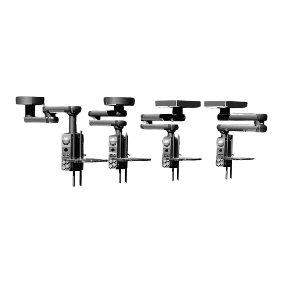
Overview of the pendant system ™ Figure 3: Scope of delivery of Navigator 340° 340° 340° 1568907, Edition 2019-04, Version 0... - Page 11 See Figure 3: on page 10” Interface plate (Single / Duo) – pre-assembled Intermediate ceiling – installed by the customer on site ™ Scope of delivery of Navigator The scope of delivery can vary depending on the individual order. Canopy (Single / Duo) (Flat / High) (depending on the version): Installation as described in Chapter 14 on page 67 –...
-
Page 12: Scope Of Delivery Of Navigator ™ Xxl
Overview of the pendant system ™ Figure 4: Scope of delivery of Navigator 340° 340° 340° 1568907, Edition 2019-04, Version 0... - Page 13 See Figure 4: on page 12” Interface plate (Single / Duo) – pre-assembled Intermediate ceiling – installed by the customer on site ™ Scope of delivery of Navigator The scope of delivery can vary depending on the individual order. Canopy (Single / Duo) (Flat / High) (depending on the version): Installation as described in Chapter 14 on page 67 –...
-
Page 14: Overview Of Optional Accessories
Overview of optional accessories Figure 5: Scope of optional accessories 1568907, Edition 2019-04, Version 0... -
Page 15: Scope Of Delivery Of Optional Accessories
See Figure 5: on page 14” Upon delivery of the system from the factory the following options are already assembled: 1.10 Scope of delivery of optional accessories Indirect extension arm lighting: For a retrofit: Installation as described in Chapter 11.4.2 on page 52 ™... -
Page 16: Safety Instructions
Safety Instructions Approved Nuvo adaptions Approved adaptions The following Nuvo products are approved for use on the pendant system: • Nuvo products in accordance with Chapter 20, “Approved Nuvo Products”, on page 88 Combination with products of other manufacturers Read the Installation Instructions •... -
Page 17: Supplementary Symbols Used In The Safety Instructions
Supplementary symbols used in the safety instructions Explosion hazard: warns of the improper use of oxygen (see Chapter 2.11 on page 21). Danger of fire: warns of the improper use of oxygen (see Chapter 2.11 on page 21). Electric shock hazard: warns of electric shock which can lead to severe injury or even death. -
Page 18: Intended Purpose
Atmospheric pressure: indicates the permissible atmospheric pressure values in a range from 500hPa to 1060hPa for transport and storage. Relative humidity: indicates the permissible humidity values in a range from 10% to 75% for transport and storage. Ambient temperature: indicates the permissible ambient temperature values in a range from -25°C to 70°C for transport and storage. -
Page 19: Ambient Conditions
The rating plates are attached to the top side of the extension arms. max. load 370 kg Manufactured for Serial number Medical Illumination International, 547 Library Street, San Fernando, CA 91340 USA • The rating plate indicates the serial number (SN) of the pendant sys- tem. -
Page 20: Retrofit To An Already Installed Ceiling Mount
Retrofit to an already installed ceiling mount WARNING Risk of the ceiling mount dropping In the case of retrofits to an already installed ceiling mount the fixing ele- ments used must be inspected by a structural analyst and approved for the new pendant system: •... -
Page 21: Proper Use Of Oxygen
2.11 Proper use of oxygen DANGER Oxygen explosion Oxygen becomes explosive when in contact with oils, greases and lubri- cants. Compressed oxygen presents an explosion hazard: • Make sure that the oxygen and gas outlet points are free from oily, greasy and lubricating materials! •... -
Page 22: Further Applicable Installation Instructions
Further Applicable Installation Instructions Figure 7: Overview of the structure of these Installation The Installation Instructions for the entire pendant system consist of sep- Instructions arate documents. For this reason, these Installation Instructions are only valid and complete if all the documents are available at the place of installation. -
Page 23: Installation Equipment Required
Installation Equipment Required • Lifting device or forklift with a permitted payload of at least 250kg Alternatively, a hoisting winch with an admissible payload of at least 250kg can be used if space is limited: – Check that the pendant system is sufficiently secured before lifting it. -
Page 24: Load Data
Load Data ™ ™ Load data of Navigator and Navigator – In- Figure 8: Load data of Navigator ™ and Navigator ™ – Inverted, verted Single version 5.1.1 Load data of the Single version (See "Figure 8") The data required for calculating the ceiling load is indicated in the tables below. -
Page 25: Load Data Of Navigator ™ Xl
5.1.2 Load data for support arm combinations Figure 9: Load data for support arm combinations ™ ™ (Navigator and Navigator Lift 180) (See "Figure 9") The vertical weight forces and bending moments of the various pendant systems or Duo versions can be added. Example: ™... -
Page 26: Load Data Of The Single Version
™ Load data of Navigator ™ Figure 10: Load data of Navigator XL, Single version 5.2.1 Load data of the Single version (See "Figure 10") The data required for calculating the ceiling load is indicated in the tables below. When mounting the pendant system to the Intermediate ceiling set, the vertical weight force of the Intermediate ceiling set (the values correspond to the maximum load) must be added to the corresponding values of the pendant system in order to determine the ceiling load. - Page 27 5.2.2 Load data for support arm combinations Figure 11: Load data for support arm combinations ™ ™ (Navigator XL and Navigator Lift 180) (See "Figure 11") The vertical weight forces and bending moments of the various pendant systems or Duo versions can be added. Example: ™...
-
Page 28: Load Data Of Navigator ™ Xxl
™ Load data of Navigator ™ Figure 12: Load data of Navigator XXL, Single version 5.3.1 Load data of the Single version (See "Figure 12") The data required for calculating the ceiling load is indicated in the tables below. When mounting the pendant system to the Intermediate ceiling set, the vertical weight force of the Intermediate ceiling set (the values correspond to the maximum load) must be added to the corresponding values of the pendant system in order to determine the ceiling load. -
Page 29: Load Data For Support Arm Combinations
5.3.2 Load data for support arm combinations Figure 13: Load data for support arm combinations ™ ™ (Navigator XXL and Navigator Lift 180) (See "Figure 13") The vertical weight forces and bending moments of the various pendant systems or Duo versions can be added. Example: ™... -
Page 30: Mounting Threaded Bolts To The Interface Plate
Mounting Threaded Bolts to the Interface Plate Mounting situation: Mounting the interface plate Figure 14: Cutting and installing the threaded bolts for the to the raw ceiling without intermediate ceiling Single / Duo interface plate on the raw ceiling 6.1.1 Versions (See "Figure 14") The Figures illustrate the interface plate , Single (round shape), for in-... -
Page 31: Mounting The Upper Insulations To The Threaded Bolts
6.1.4 Mounting the upper insulations to the threaded bolts Figure 15: Mounting the upper insulations to the threaded bolts (See "Figure 15") The 6 (Single version) or 12 (Duo version) hexagonal nuts M16② must be mounted to the threaded bolts M16① at an exact distance to each oth- For each threaded bolt M16①... -
Page 32: Mounting Situation: Interface Plate On The Raw Ceiling With Intermediate Ceiling
Mounting situation: Interface plate on the raw Figure 16: Cutting the threaded bolts for the Single / Duo ceiling with intermediate ceiling interface plate on the raw ceiling to length 6.2.1 Versions (See "Figure 16") The Figures illustrate the interface plate , Single (round shape), for in- ™... -
Page 33: Mounting The Threaded Bolts To The Single / Duo Interface Plate
6.2.3 Mounting the threaded bolts to the Single / Duo interface Figure 17: Mounting the upper insulations to the plate threaded bolts (See "Figure 17") Screw 1 hexagonal nut M16② each onto the 6/12 threaded bolts M16③ and then place 1 spring ring① each. ... -
Page 34: Mounting The Upper Insulations To The Threaded Bolts
6.2.4 Mounting the upper insulations to the threaded bolts Figure 18: Mounting the upper insulations to the threaded bolts (See "Figure 18") For each threaded bolt M16① screw a hexagonal nut M16② onto the threaded bolts M16①. Adjust the distance between the hexagonal nuts M16② and the interface plate •... -
Page 35: Mounting Situation: Interface Plate On The Intermediate Ceiling Set
Mounting situation: Interface plate on the inter- Figure 19: Mounting the threaded bolts mediate ceiling set 6.3.1 Versions (See "Figure 19") The Figures illustrate the interface plate , Single (round shape), for in- ™ ™ stalling the Navigator and Navigator –... -
Page 36: Mounting The Upper Insulations To The Threaded Bolts
6.3.3 Mounting the upper insulations to the threaded bolts Figure 20: Mounting the upper insulations to the threaded bolts (See "Figure 20") The 6 (Single version) or 12 (Duo version) hexagonal nuts M16② must be mounted to the threaded bolts M16 x 330mm① at an exact distance to each other. -
Page 37: Pre-Assembly: Mounting The Enclosed Ceiling Tube To The Extension Arm
Pre-Assembly: Mounting the enclosed ceiling tube to the extension arm Components described in this chapter Figure 21: Components described in this chapter (See "Figure 21") ™ For long ceiling tubes or for the version Navigator – Inverted the ceiling tube is supplied as a separate component. -
Page 38: Mounting The Ceiling Tube Supplied As A Separate Component
Mounting the ceiling tube supplied as a sepa- Figure 22: Installing the ceiling tube rate component 7.2.1 Mounting a ceiling tube (See "Figure 22") ™ The Figure shows the Navigator ceiling tube with 8 Allen cylinder screws M10 x 25mm① – 8.8 – DIN EN ISO 4762 as an example. The simplified representation illustrates the extension arm without pre-assembled cables. -
Page 39: Mounting The Strain Relieving Mechanism In The Ceiling Tube
7.2.2 Mounting the strain relieving mechanism in the ceiling Figure 23: Mounting the strain relieving mechanism in the tube ceiling tube (See "Figure 23") The Figure shows the Navigator ™ ceiling tube with 8 Allen cylinder screws M10 x 25mm① – 8.8 – DIN EN ISO 4762 as an example. The simplified representation illustrates the extension arm without pre-assembled cables. -
Page 40: Subsequently Mounting The Earthing Cable To The Ceiling Tube
7.2.3 Subsequently mounting the earthing cable to the ceiling Figure 24: Subsequently mounting the earthing cable to the tube ceiling tube (See "Figure 24") The system is delivered with the earthing cable pre-assembled! Fit 1 lock washer S4②/④ each above and below the ring cable lug③... -
Page 41: Mounting The Extension Arm To The Threaded Bolts Of The Interface Plate
Mounting the Extension Arm to the Threaded Bolts of the Interface Plate Components described in this chapter Figure 25: Components described in this chapter (See "Figure 25") • The extension arm illustrated in the Figure for the single- or dual-arm variants is mounted to the threaded bolts of the interface plate •... -
Page 42: Mounting The Extension Arm
Mounting the extension arm Figure 26: Mounting the extension arm (See "Figure 26") 8.2.1 Versions (See "Figure 26") The Figures illustrate the interface plate , Single (round shape), for in- stalling the Navigator ™ and Navigator ™ – Inverted version. The installa- tion steps required for the Navigator ™... -
Page 43: Aligning The Extension Arm With The Interface Plate, Single
Aligning the extension arm with the interface Figure 27: Aligning the extension arm with the interface plate, plate, Single Single (See "Figure 27") The Figure only shows a simplified representation of the flange③ with ceiling tube to be mounted to the threaded bolts. Other components pre- assembled to the flange③, such as the extension arm, cables, etc., are not represented. -
Page 44: Aligning The Extension Arm With The Duo Interface Plate
Aligning the extension arm with the Duo inter- Figure 29: Aligning the extension arm with the Duo interface face plate plate (See "Figure 29") The Figure only shows a simplified representation of the flange③ with ceiling tube to be mounted to the threaded bolts. Further components pre-assembled to the flange③, such as the extension arm, cables, etc., are not represented. -
Page 45: Mounting The Drop Tube To The Extension Arm
Mounting the Drop tube to the Extension Arm Components described in this chapter Figure 31: Components described in this chapter (See "Figure 31") • The Drop tube illustrated in the Figure is mounted to the extension arm of the single- or dual-arm variants. •... -
Page 46: Mounting The Drop Tube To The Extension Arm
Mounting the Drop tube to the extension arm Figure 32: Mounting the Drop tube to the extension arm (See "Figure 32") The Figure shows a magnified sectional view of the extension arm with- out its top side. Push the fastening plate 8 x M10③ from the front side① into the ex- tension arm and position it. -
Page 47: Mounting Optional Accessories
Mounting Optional Accessories 10.1 Mounting the extension arm lighting (for retrofit Figure 33: Mounting the extension arm lighting only) (See "Figure 33") ™ The Figure shows the Navigator version. The installation steps required for Navigator ™ XL and Navigator ™ XXL versions are identical. -
Page 48: Mounting The Brake Indicators (For Retrofit Only)
10.2 Mounting the brake indicators (for retrofit only) Figure 34: Mounting the brake indicators (See "Figure 34") The Figure shows the Navigator ™ version. The installation steps required ™ ™ for the Navigator XL and Navigator XXL versions are identical. ™... -
Page 49: Mounting Cables
Mounting Cables 11.1 Versions ™ The insertion of the cables is described using the example of the Navigator version. The installation steps required for the Navigator ™ XL and Navigator ™ XXL versions are identi- cal. 11.2 Safety Instructions WARNING Electric shock hazard Power cables may have been laid in the pendant system. -
Page 50: Connecting The Cables And Hoses To The Support Arm, Dual-Arm Variant
11.3 Connecting the cables and hoses to the support arm, dual- arm variant The supply cables and hoses are pre-assembled by Nuvo. The instructions in the para- graphs below only refer to the replacement of supply cables and hoses. NOTE – Version Navigator ™... - Page 51 Figure 35: Connecting the cables and pipes to the support arm, dual-arm variant Table 05: Cable assignment of the pendant system, dual-arm variant No. in From Designation Length [mm] Remark Fig. 34 ⑥ Bearing unit Distributor board Integrated in the bearing unit ⑦...
-
Page 52: Connecting Optional Accessories To The Support Arm, Dual-Arm Variant
11.4 Connecting optional accessories to the support arm, dual- arm variant 1. Observe the safety instructions in Chapter 11.1 on page 49. ™ NOTE – Version Navigator – Inverted For the version Navigator ™ – Inverted the extension arm lighting is mounted to the front upper extension arm (not illustrated). - Page 53 Figure 36: Connecting optional accessories to the support arm, dual-arm variant Table 06: Cable assignment of the pendant system, dual-arm variant – Options No. in From Designation Length [mm] Remark Fig. 35 ④ Lower brake Distributor board Brakeguide2/PCB cable indicator ⑤...
-
Page 54: Connecting The Earthing Cables To The Support Arm, Dual-Arm Variant
11.5 Connecting the earthing cables to the support arm, dual-arm variant (See "Figure 37“) The earthing cables are pre-assembled in the extension arm and must be laid and connected in the direction of the arrow. ™ NOTE – Version Navigator –... - Page 55 Figure 37: Connecting the earthing cables to the support arm, dual-arm variant Figure 38: Routing the supply cables and hoses through the support arm, dual-arm variant 1568907, Edition 2019-04, Version 0...
-
Page 56: Connecting The Cables And Pipes To The Support Arm, Single-Arm Variant
11.7 Connecting the cables and pipes to the support arm, single- arm variant The supply cables and hoses are pre-assembled by Nuvo. The instructions in the para- graphs below only refer to the replacement of supply cables and hoses. 1. Observe the safety instructions in Chapter 11.1 on page 49. 11.7.1 Checking the power pack and distributor board connections (See "Figure 39“) 2. - Page 57 Figure 39: Connecting the cables and pipes to the support arm, single-arm variant Table 07: Cable assignment of the pendant system, single-arm variant No. in From Designation Length [mm] Remark Fig. 38 ⑥ Front plate Drop tube Navigator M6/Navigator M6 Integrated in the Navigator M6 socket interface cable...
-
Page 58: Connecting Optional Accessories To The Support Arm, Single-Arm Variant
11.8 Connecting optional accessories to the support arm, single- arm variant 1. Observe the safety instructions in Chapter 11.1 on page 49. 11.8.1 Connecting an optional brake indicator (See "Figure 40“) 1. Route the 2 cables⑧ of the upper brake indicator through the extension arm and plug it onto the corresponding distributor board sockets②... - Page 59 Figure 40: Connecting optional accessories to the support arm, single-arm variant Table 08: Cable assignment of the pendant system, single-arm variant – Options No. in From Designation Length [mm] Remark Fig. 39 ③ Navigator M6 Distributor board Navigator M6, PCB 230V cable 3900 Integrated in the Navigator M6...
-
Page 60: Connecting Earthing Cables To The Support Arm, Single-Arm Variant
11.9 Connecting earthing cables to the support arm, single-arm variant (See "Figure 41“) The earthing cables are pre-assembled in the extension arm and must be laid and con- nected in the direction of the arrow. 1. Observe the safety instructions in Chapter 11.1 on page 49. 2. - Page 61 Figure 41: Connecting earthing cables to the support arm, single-arm variant Figure 42: Routing the supply cables and hoses through the pendant system, single-arm variant 1568907, Edition 2019-04, Version 0...
-
Page 62: Connecting The Supply Cables
Connecting the Supply Cables 12.1 Safety Instructions WARNING Qualification of installation personnel The electrical connection of the pendant system and the Navigator M6 may only be performed by a qualified electrician: • Observe the safety instructions set out in the Installation Instructions Part 1 –... -
Page 63: Installing Gas Supply And Exhaust Air Ducts
12.2 Installing gas supply and exhaust air ducts Figure 43: Installing gas supply and exhaust air ducts (See "Figure 43") Observe the safety instructions in Chapter 12.1 on page 62. NOTE – Make sure that the gas types are correctly assigned •... -
Page 64: Connecting The Earthing Cables
12.3 Connecting the earthing cables Figure 44: Connecting the earthing cables (See "Figure 44") The Figure illustrates the interface plate , Single (round shape), for in- ™ ™ stalling the Navigator and Navigator – Inverted version. The installa- ™ ™ tion steps required for the Navigator XL and Navigator XXL interface... -
Page 65: Connecting Power Cables
12.4 Connecting power cables Figure 45: Connecting power cables (See "Figure 45") The Figure illustrates the interface plate , Single (round shape), for in- ™ ™ stalling the Navigator and Navigator – Inverted version. The installa- ™ ™ tion steps required for the Navigator XL and Navigator XXL interface plate... -
Page 66: Inspections
Inspections 13.1 Gas inspection 1. Gas outlets and marking according to DIN EN ISO 9170-1 or DIN EN ISO 9170-2 2. Leakage, in accordance with DIN EN ISO 11197 3. Congestion, in accordance with DIN EN ISO 7396-1 or DIN EN ISO 7396-2 4. -
Page 67: Mounting The Canopy And The Cover Caps
Mounting the Canopy and the Cover Caps 14.1 Mounting a Single / Duo canopy Figure 46: Preparing the installation of the canopy 14.1.1 Preparing the installation of the canopy (See "Figure 46") The Figure illustrates the installation steps for the Duo canopy. The in- stallation procedure for the Single canopy is identical. -
Page 68: Mounting The Single Canopy (Navigator ™ Only)
™ 14.2 Mounting the Single canopy (Navigator only) Figure 48: Preparing the installation of the canopy 14.2.1 Preparing the installation of the canopy (See "Figure 48") The Figure shows a simplified illustration of the interface plate without ca- bles and without the extension arm. Screw the hexagonal nuts M10①... -
Page 69: Mounting/Dismantling The Cover Caps To/From The Extension Arm
14.3 Mounting/dismantling the cover caps to/from the Figure 50: Mounting the coper caps extension arm 14.3.1 Mounting the coper caps (See "Figure 50") ™ The Figure shows the Navigator version. The installation steps required ™ ™ ™ for the Navigator –... -
Page 70: Adjustments
Adjustments 15.1 Condition of the swivel stop on the extension Figure 52: Condition of the swivel stop on the extension arm arm supplied supplied 15.1.1 Extension arm with pre-assembled swivel stop (See "Figure 52") The system is supplied by default with the 2 ball stops② and the setscrew①... -
Page 71: Adjusting The Swivel Stop On The Extension Arm
15.2 Adjusting the swivel stop on the extension arm ™ Figure 53: Adjusting the swivel stop on the Navigator exten- sion arm (See "Figure 53") ™ ™ (from top to bottom: Navigator / Navigator – Inverted / The swivel stops must be adjusted during installation independently of Navigator ™... -
Page 72: Mounting The Swivel Stop
15.2.3 Mounting the swivel stop Figure 54: Mounting the swivel stop (See "Figure 54") The assignment and size of the setscrew① and the ball point③ for the different versions of the pendant system are described in Chapter 15.2.1, “Versions”, on page 71 . Rotate the extension arm towards the desired end stop posi- tion and then insert 1 ball stop③... -
Page 73: Dismantling The Swivel Stop
15.2.4 Dismantling the swivel stop Figure 55: Dismantling the swivel stop (See "Figure 55") The assignment and size of the setscrew① and the ball stop③ for the different pendant system versions is described in Chapter 15.2.1, “Versions”, on page 71. Unscrew a setscrew①... -
Page 74: Initial And Repeated Commissioning And Handover
Initial and Repeated Commissioning and Handover Initial commissioning 1. The pendant system must be installed. Instructions for installation are included in the scope of delivery of the product. 2. For start-up following installation, proper initial commissioning must be carried out for the entire pendant system and the Navigator M6. -
Page 75: Technical Description
Technical Description ™ 17.1 Navigator – Single-arm variant ™ 17.2 Navigator – Dual-arm variant 1568907, Edition 2019-04, Version 0... -
Page 76: Navigator ™ - Inverted - Dual-Arm Variant
™ 17.3 Navigator – Inverted – Dual-arm variant 1568907, Edition 2019-04, Version 0... -
Page 77: Navigator ™ Xl - Single-Arm Variant
™ 17.4 Navigator XL – Single-arm variant ™ 17.5 Navigator XL – Dual-arm variant 1568907, Edition 2019-04, Version 0... -
Page 78: Navigator ™ Xxl - Dual-Arm Variant
™ 17.6 Navigator XXL – Dual-arm variant 1568907, Edition 2019-04, Version 0... -
Page 79: Technical Data
Technical Data Modes of operation • The Navigator ™ pendant system is suitable for continuous operation. Duty cycle of the electromagnetic brakes • The maximum duty cycle of the electromagnetic brakes must not exceed 1 minute. • If the electromagnetic brakes are actuated over a longer period of time, the power pack can switch off automatically as a protection measure against overheating. - Page 80 Dead weight of the Single-arm variant ™ Navigator XL* pendant system Extension arm 600mm ................... 40.1kg Extension arm 800mm ................... 45.1kg Extension arm 1000mm ..................50.1kg Extension arm 1200mm ..................55.1kg Extension arm 1400mm ..................60.1kg Extension arm 1600mm ..................65.1kg Dual-arm variant Extension arm 600/600mm ..................
- Page 81 ™ Dead weight of the ceiling tube Navigator Flange ........................6.0kg ™ and Navigator – Inverted pendant system Steel tube .......................24kg/m Dead weight of the ceiling tube of the Flange ........................7.5kg Navigator ™ XL and Steel tube ......................31.7kg/m ™ Navigator XXL pendant system Dead weight of the Drop tube Bearing unit ........................5kg Drop tube .........................8kg/m...
- Page 82 Approved adaptions The following products are approved as adaptions to the pendant system: • Chapter 20, “Approved Nuvo Products”, on page 88 • Chapter 21, “Optional Accessories”, on page 88 – The components are adapted to each other and safe to operate. Any other type of installation, and in particular the use of components from third-party manufacturers, is strictly prohibited because these components can be potential sources of danger.
-
Page 83: Electromagnetic Compatibility (Emc) Information
Electromagnetic Compatibility (EMC) Information 19.1 Guidelines and manufacturer’s declarations 19.1.1 Electromagnetic emissions The Navigator ™ is intended for use in the ELECTROMAGNETIC ENVIRONMENT speci- fied below. The customer or the user of the Navigator ™ must ensure that it is used in such an environment. -
Page 84: Electromagnetic Immunity
19.1.2 Electromagnetic immunity The Navigator ™ is intended for use in the ELECTROMAGNETIC environment specified below. The customer or the user of the Navigator ™ should ensure that it is used in such an environment. Interference immunity test Test level in accordance with IEC 60601 Test result Electrostatic discharge in accordance with ±8kV contact... - Page 85 Cont. The Navigator ™ is intended for use in the ELECTROMAGNETIC environment specified below. The customer or the user of the Navigator ™ should ensure that it is used in such an environment. Interference immunity test Test level in accordance with IEC 60601 Compliance level Immunity to conducted disturbances, passed...
-
Page 86: Test Specifications
19.1.3 Test specifications Test specifications for the INTERFERENCE IMMUNITY of ENCLOSURES against high- frequency wireless communication facilities Test frequency Frequency band Radio service Modulation Maximum Distance IMMUNITY TEST power LEVEL 380 to 390 TETRA 400 Pulse modulation 18Hz 430 to 470 GMRS 460, FRS 460 ±... - Page 87 WARNING Do not operate this device immediately next to or together with other devices stacked on top of each other because this could result in improper operation. If operation in the described manner is unavoidable, this device and all other devices should be monitored in order to ensure proper opera- tion."...
-
Page 88: Approved Nuvo Products
Approved Nuvo Products Designation Navigator M6 and approved end devices in accordance with the current Operating Instructions of the Navigator M6. Optional Accessories Designation Dead weight Maximum payload Indirect extension arm lighting 2.0 kg Brake indicator lighting board 0.1 kg Adapter Acrobat Swing 3p, L150* 1,6kg 10kg / 113Nm... -
Page 89: Notes
Notes 1568907, Edition 2019-04, Version 0... - Page 90 1568907, Edition 2019-04, Version 0...
- Page 91 1568907, Edition 2019-04, Version 0...
Need help?
Do you have a question about the nuvo Navigator and is the answer not in the manual?
Questions and answers