Table of Contents
Advertisement
Advertisement
Table of Contents

Related Manuals for MEDICAL ILLUMINATION System One


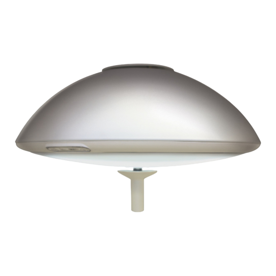
Summary of Contents for MEDICAL ILLUMINATION System One
- Page 2 In accordance with IEC-60601-2-41 Intended use The System One surgical lighting system is an AC powered device which provides a focusable field of illumination for general examination and surgery. System One Surgical Lighting System Service Manual (1003239)
- Page 3 Revisions Revision Pages Affected Date letter number Initial Release 7-01-02 ECO-365 i,4,12,13,16,17,18,20 7-23-02 ECO-420 Cover,10,14,18,25,26,32, 1-7-03 33,34,35,38-48 ECO-436 3-6-03 ECO-439 25,32,33, 2-21-03 ECO-515 Various, Added Orbital 1-28-04 mount to manual System One Surgical Lighting System Service Manual (1003239) Page ii...
- Page 4 General Safety Instructions Section 6: Maintenance Lamp Replacement Fuse Replacement Arm Tension Adjustment Head Friction Adjustment Arm/Head Friction Adjustment(Orbital) Handle Sterilization Cleaning Instructions Maintenance Schedule Section 7: Troubleshooting General Trouble Shooting System One Surgical Lighting System Service Manual (1003239) Page iii...
-
Page 5: Table Of Contents
Table of Contents (continued) Section 8: System One Exploded Views and Parts List Electrical Schematic Ballast Assembly Ceiling Casting Assembly Ceiling Rod Assembly Arm assembly Light head assembly Extension/Adapter (Orbital) Solo Assembly (Orbital) Duo Assembly (Orbital) Trio Assembly (Orbital) System One Surgical Lighting System Service Manual (1003239) - Page 6 Figure 3- Ceiling Rod Calculation Solo Mount (Orbital) Figure 4- Ceiling Rod Calculation Duo Mount (Orbital) Figure 5- Ceiling Rod Calculation l Trio Mount (Orbital) Figure 6- Sub-Assemblies for System One Solo Mount (Traditional) Figure 7- Solo Ceiling Mount(Traditional) Figure 8- Arm and Light Head Installation...
- Page 7 CIE chromaticity coordinates measured with a spectroradiometer. Handle Sterilizable Device when properly sterilized maintains a sterile area in order to handle it under aseptic conditions when attached to the equipment. System One Surgical Lighting System Service Manual (1003239) Page 1...
- Page 8 Ft-Lbs Foot-pounds. The unit of measurement of torque which is caused by an off-center load. System One Surgical Lighting System Service Manual (1003239) Page 2...
- Page 9 List of symbols U.L Listing marking Read accompanying documents C.E. Marking Fuse marking Protective earth ground Neutral conductor Caution Electric shock hazard Light intensity indicator Dimming control button Light head on/off button System One Surgical Lighting System Service Manual (1003239) Page 3...
- Page 10 120 VAC, 50/60 Hz, 340 Watts CS2S2230, SS2S2230 230 VAC, 50/60 Hz, 340 Watts CS2S2S2120, SS2S2S2120 120 VAC, 50/60 Hz, 510 Watts CS2S2S2230, SS2S2S2230 230 VAC, 50/60 Hz, 510 Watts Bulb life 1,000 hours(average) System One Surgical Lighting System Service Manual (1003239) Page 4...
- Page 11 Illuminance at bottom of standard tube with two masks Environmental Parameter Value Operating temperature 41-104 deg F (5-45 Degrees Celsius) Storage temperature Range 41-104 deg F (5-45 Degrees Celsius) Humidity 10-90% relative humidity System One Surgical Lighting System Service Manual (1003239) Page 5...
- Page 12 This warranty applies exclusively to the repair or replacement of parts recognized as defective by Medical Illumination International, Inc., are in normal use, and have not been modified or repaired by unauthorized personnel. This warranty supersedes all other guarantees or warranties, expressed or implied.
- Page 13 • The light head switches secondary transformer power only. It is recommended that the System One Surgical Lighting System is connected to its own supply circuit with integral circuit breaker. The circuit breaker will act as the supply main disconnect switch.
-
Page 14: Figure 1- Ceiling Rod Calculation Solo Ceiling Mount
10-11’(3,0-3,3m) 31”(787,4mm) 44.5”(1130,3mm) 120”(3,0m) 75.5” (1917,7mm) 11-12’(3,3-3,6m) 43”(1092,2mm) 56.5”(1435,1mm) 132”(3,3m) 75.5” (1917,7mm) 12-13’(3,6-3,9m) 55”(1397mm) 68.5”(1739,9mm) 144”(3,6m) 75.5” (1917,7mm) 25”635mm) 33”(838,2mm) 41”(1041,4mm) Figure 1 Ceiling Rod Calculation Solo Ceiling Mount (Traditional) System One Surgical Lighting System Service Manual (1003239) Page 8... -
Page 15: Figure 2- Ceiling Rod Calculation Duo Mount(Traditional)
10-11’(3,0-3,3m) 31”(787,4mm) 47”(1193,8mm) 120”(3,0m) 73” (1854,2mm) 11-12’(3,3-3,6m) 43”(1092,2mm) 59”(1498,6mm) 132”(3,3m) 73” (1854,2mm) 12-13’(3,6-3,9m) 55”(1397mm) 71”(1803,4mm) 144”(3,6m) 73” (1854,2mm) 25”(635mm) 33”(838mm) 41”(1041,4mm) Figure 2 Ceiling Rod Calculation Duo Ceiling Mount (Traditional) System One Surgical Lighting System Service Manual (1003239) Page 9... -
Page 16: Figure 3- Ceiling Rod Calculation Solo Mount (Orbital)
144”(3,6m) 84.5” (20302mm) “ X” VALUE (TO BOTTOM OF EXTENSION ARM) 20° 25”635mm) 41”(1041,4mm) 33”(838,2mm) 70° ‘ Y’ VALUE (DISTANCE TO FLOOR) Figure 3 Ceiling Rod Calculation Solo Mount (Orbital) System One Surgical Lighting System Service Manual (1003239) Page 10... -
Page 17: Figure 4- Ceiling Rod Calculation Duo Mount (Orbital)
43”(1092,2mm) 63.75”(1,619mm) 144”(3,6m) 80.25 (2038mm) “X” VALUE 20° (TO BOTTOM OF EXTENSION ARM) 25”(635mm) 70° 29”(736,6mm) 41”(1041,4mm) “Y” VALUE DISTANCE TO FLOOR Figure 4 Ceiling Rod Calculation Duo Mount (Orbital) System One Surgical Lighting System Service Manual (1003239) Page 11... -
Page 18: Figure 5- Ceiling Rod Calculation L Trio Mount (Orbital)
43”(1092,2mm) 68.0”(1,727mm) 144”(3,6m) 76.0” (1,930mm) “X” VALUE 20° (TO BOTTOM OF EXTENSION ARM) 25”(635mm) 25”(635mm) 41”(1041,4mm) 70° “Y” VALUE DISTANCE TO FLOOR Figure 5 Ceiling Rod Calculation Trio Mount (Orbital) System One Surgical Lighting System Service Manual (1003239) Page 12... -
Page 19: Figure 6- Sub-Assemblies For System One Solo Mount (Traditional)
FIGURE 6 Sub-assemblies for System One Solo Ceiling Mount (Traditional) GENERAL INFORMATION The System One solo ceiling mount is shipped in three separate cartons. The ceiling casting assembly, hardware kit and installation manual is in one carton. The arm assembly, cable assembly and ceiling rod is in one carton. -
Page 20: Figure 7- Solo Ceiling Mount(Traditional)
• Slide the cable assembly through the center of the ceiling rod with the Molex connector protruding approximately 1” from the shaft protruding from the ceiling rod. System One Surgical Lighting System Service Manual (1003239) Page 14... - Page 21 Figure 8). Failure to install or tighten the 8-32 flat head screws can cause the head assembly to fall causing serious injury and/or property damage. System One Surgical Lighting System Service Manual (1003239) Page 15...
-
Page 22: Figure 8- Arm And Light Head Installation
Figure 8 Arm and Light Head Installation Figure 9 Locking Pin Removal Note: Locking Pin Do not remove pin Screwdriver until light head is Slots Arm Cover installed on arm System One Surgical Lighting System Service Manual (1003239) Page 16... -
Page 23: Figure 10- Sub-Assemblies For System One Duo Mount (Traditional)
Sub-assemblies for System One Duo Ceiling Mount(Traditional) GENERAL INFORMATION The System One Duo ceiling mount is shipped in five separate cartons. The ceiling casting assembly, hardware kit and installation manual is in one carton. The arm assemblies, cable assemblies and ceiling rod are in two cartons. The head assemblies and lamp holders are in the last two cartons. -
Page 24: Figure 11- Duo Ceiling Mount (Traditional)
Tighten the three 3/8-24 Hex head screws to secure the ceiling rod into place. Failure to tighten the 3/8-24 hex screws can cause the arm/head assembly to become unstable causing serious injury and/or property damage. System One Surgical Lighting System Service Manual (1003239) Page 18... - Page 25 ¼- 28 socket head cap screws provided in the hardware kit.(See Figure 12). Repeat for second arm assembly. System One Surgical Lighting System Service Manual (1003239) Page 19...
-
Page 26: Figure 12 Arm And Light Head Installation
S2 Light Head Assembly Ceiling Rod Large Arm Ring Molex Connectors ¼-28 Socket Head Cap Screws 8-32 Head Attachment screws Arm Assembly Small Arm Ring Figure 12 Arm and Light Head Installation System One Surgical Lighting System Service Manual(1003239 Page 20... -
Page 27: Figure 13 Locking Pin Removal
Figure 13 Locking Pin Removal • Install the arm cover. • Installation is now complete. Refer to operation and maintenance sections before trying to operate light and arm mechanism System One Surgical Lighting System Service Manual (1003239) Page 21... -
Page 28: Figure 14- System One Retro-Fit Duo Mount (Traditional)
Section 3 System One Installation Duo Ceiling Mount Retrofit(Traditional) The System One Surgical light system is convertible from a solo mount to a duo mount. Double Mount Cable Assembly Main Bearing Assembly Ballast Assembly Large Arm Ring Arm Assembly Small Arm Ring... - Page 29 Section 3 System One Installation Duo Ceiling Mount Retrofit(Traditional) • Turn off main power to the light (at the circuit breaker). Failure to turn off main power to the light can result in an electric shock • Remove plastic arm cover, rotate arm to horizontal and insert locking pin.(See Figure 13...
- Page 30 Section 3 System One Installation Duo Ceiling Mount Retrofit(Traditional) • Slide the decorative arm rings over the arm assemblies (arm rings are supplied in the hardware kit). • While supporting each arm assembly connect the two Molex connectors together. Slide the arm assembly over the shaft protruding from the ceiling rod and secure using the four ¼-28...
-
Page 31: Figure 15- Sub-Assemblies For System One Solo Mount (Orbital)
FIGURE 15 Sub-assemblies for System One Solo Ceiling Mount (Orbital) GENERAL INFORMATION The System One orbital solo ceiling mount is shipped in three separate cartons. The ceiling casting assembly, hardware kit and this manual are in one carton. The arm assembly and ceiling rod/adapter assembly are in one carton. -
Page 32: Figure 16-Solo Ceiling Mount (Orbital)
Install the 3/8” diameter dowel pin through the ceiling rod and seat inside the groove provided in the ceiling casting. Failure to install the 3/8” diameter dowel pin can cause the arm to fall from the ceiling causing serious injury and/or property damage. System One Surgical Lighting System Service Manual (1003239) Page 26... - Page 33 450 ft-lbs. The structural mount should meet all local building codes. A structural mount that does not meet these minimum conditions can cause serious injury and/or property damage. System One Surgical Lighting System Service Manual (1003239) Page 27...
- Page 34 • Remove the arm locking pin and install the plastic arm cover. • Installation is now complete. Refer to operation and maintenance sections before trying to operate light and arm. System One Surgical Lighting System Service Manual (1003239) Page 28...
-
Page 35: Figure 17 Arm And Light Head Installation
Figure 17 Arm and Light Head Installation Note: Locking Pin Do not remove pin Screwdriver until light head is Slots Arm Cover installed on arm Figure 18 Locking Pin Removal System One Surgical Lighting System Service Manual (1003239) Page 29... -
Page 36: Figure 19- Sub-Assemblies For System One Duo Mount (Orbital)
Duo Ceiling Mount (Orbital) GENERAL INFORMATION The System One orbital double ceiling mount is shipped in four separate cartons. The ceiling casting assembly, hardware kit and installation manual are in one carton. The arm assemblies and ceiling rod/adapter assembly are in one carton. The head assemblies are in the last cartons. -
Page 37: Figure 20- Duo Ceiling Mount (Orbital)
Install the 3/8” diameter dowel pin through the ceiling rod and seat inside the groove provided in the ceiling casting. Failure to install the 3/8” diameter dowel pin can cause the arm to fall from the ceiling causing serious injury and/or property damage. System One Surgical Lighting System Service Manual (1003239) Page 31... - Page 38 450 ft-lbs. The structural mount should meet all local building codes. A structural mount that does not meet these minimum conditions can cause serious injury and/or property damage. System One Surgical Lighting System Service Manual (1003239) Page 32...
- Page 39 • Remove the arm locking pins and install the plastic arm covers. • Installation is now complete. Refer to operation and maintenance sections before trying to operate light and arm. System One Surgical Lighting System Service Manual (1003239) Page 33...
-
Page 40: Figure 21- Arm And Light Head Installation
Figure 21 Arm and Light Head Installation Figure 22 Locking Pin Removal Note: Locking Pin Do not remove pin until Screwdriver light head is installed Slots Arm Cover on arm System One Surgical Lighting System Service Manual (1003239) Page 34... -
Page 41: Figure 23- Sub-Assemblies For System One Trio Mount (Orbital)
Trio Mount Components (Orbital) GENERAL INFORMATION The System One orbital triple ceiling mount is shipped in five separate cartons. The ceiling casting assembly, hardware kit and installation manual are in one carton. The arm assemblies and ceiling rod/adapter assembly are in one carton. The head assemblies are in the last three cartons. -
Page 42: Figure 24-Trio Ceiling Mount (Orbital)
Install the 3/8” diameter dowel pin through the ceiling rod and seat inside the groove provided in the ceiling casting. Failure to install the 3/8” diameter dowel pin can cause the arm to fall from the ceiling causing serious injury and/or property damage. System One Surgical Lighting System Service Manual (1003239) Page 36... - Page 43 450 ft-lbs. The structural mount should meet all local building codes. A structural mount that does not meet these minimum conditions can cause serious injury and/or property damage. System One Surgical Lighting System Service Manual (1003239) Page 37...
- Page 44 • Remove the arm locking pins and install the plastic arm covers. • Installation is now complete. Refer to operation and maintenance sections before trying to operate light and arm. System One Surgical Lighting System Service Manual (1003239) Page 38...
-
Page 45: Figure 25- Arm And Light Head Installation
Small Arm Ring Arm and Light Head Installation Figure 26 Locking Pin Removal Note: Locking Pin Do not remove pin until Screwdriver light head is installed Slots Arm Cover on arm System One Surgical Lighting System Service Manual (1003239) Page 39... -
Page 46: Figure 27 System One Head And Arm Movements
Continuous Rotation (Orbital) Continuous Light Head Rotation +20 Degree -70 Degree Rotation Touchpad Continuous Rotation Sterilizable Handle (Dimmer Control 300 Degree Rotation Figure 27 System One Head and Arm Movements System 1 Surgical Lighting System Service Manual (1003239) Page 40... - Page 47 System. Repair by unauthorized personnel could result in personal injury and/or property damage and could void warranty. After completing a repair of the System One Surgical Lighting System make sure the unit is in proper working order. Failure to do so could result in personal injury and/or property damage The System One Surgical Lighting System operates at high temperatures.
- Page 48 Do not expose the unit to excessive moisture. Failure to do so could result in personal injury and/or property damage. Do not rest articles or liquids on top of the System One Surgical Lighting System. Spilled liquids will damage the light head and arm assemblies causing an electric shock hazard.
-
Page 49: Figure 28-Lamp Replacement
System One Maintenance Lamp Replacement The System One Surgical Lighting System is equipped with a secondary lamp that will automatically illuminate if the primary lamp fails. The secondary bulb will provide adequate illumination until time is available to replace the primary lamp. When bulb replacement is necessary a yellow indicator located on the touch pad will illuminate. -
Page 50: Figure 29- Fuse Replacement
• All ballast assemblies come with dual fuses . Determine which fuse has failed and replace with Medical Illumination P/n-0003082 or P/n-0003083. For 120 VAC applications use only a 2.5 amp slo-blow fuse (0003082). For 230 VAC applications use only a 1.25 amp slo-blow fuse (0003083). -
Page 51: Figure 30-Arm Adjustment
Section 6 System One Arm Adjustment • To remove the two arm covers insert a flat bladed screwdriver in to the slots in the covers. Gently pry the covers off with the screw driver. • Lower the arm and head until the adjustment holes in the spring rod are accessible. -
Page 52: Figure 31- Light Head Friction Adjustment
Section 6 System One Head Adjustment • To adjust the friction between the head and the yoke, rotate the head until the hole and in the yoke is exposed, as shown below. • Insert the 5/16” Allen wrench into the hole and tighten the set screw to increase the head friction or loosen the set screw to decrease head friction. -
Page 53: Figure 32- Arm/Head Adjustment(Orbital Mount)
• Using the 3/16” Allen wrench (supplied in the hardware kit) turn the set screw located on the arm housing clockwise to increase friction or counterclockwise to decrease friction. (See Figure 32 for adjustment location) Friction adjustment set-screw Allen wrench Figure 32- Arm/Head Friction Adjustment System One Surgical Lighting System Service Manual (1003239) Page 47... -
Page 54: Figure 33- Handle Sterilization
Section 6 System One Handle Sterilization • Remove sterilizable handle by pressing the button near the base of the handle and pulling the handle off the handle post(See Figure 33). • Sterilize the handle utilizing steam sterilization of minimum 250° Fahrenheit for a minimum of 30 minutes in compliance with AAMI-SSSa-1988 Good Hospital Practices, Steam Sterilization and Sterility Assurance, or equivalent method. - Page 55 Section 6 System One Cleaning Instructions • The front lens is made from a UV resistant polycarbonate plastic that has an external hard coating to resist scratching. Clean the lens using glass/plastic cleaner or mild soap and water mix. It is very important to use a clean, soft cloth to avoid any scratching of the diffuser.
- Page 56 Page 46. If this does not solve the problem contact customer service as the unit may require factory repair Overall appearance Check the general aesthetics of the System One Surgical Lighting System. The unit should be kept clean and dust free. Clean and dust as necessary.
- Page 57 Section 7 System One Troubleshooting Problem Cause Remedy • • Light will not turn on No power to light Check circuit breaker • • Fuse is blown Replace fuse/fuses • • Both primary and secondary Replace bulbs bulbs have failed •...
-
Page 58: Electrical Schematic
Section 8 System One Exploded View and Part lists Electrical Schematic FUSE 5mm X 20mm FUSE 5mm X 20mm 2.5A, 250 VAC 2.5A, 250 VAC SLOW BLOW SLOW BLOW FUSE 5mm X 20mm FUSE 5mm X 20mm 1.25A, 250 VAC 1.25A, 250 VAC... -
Page 59: Ballast Assembly
Section 8 System One Exploded View and Part lists Ballast Assembly-P/N-1000295 System 1 Surgical Lighting System Service Manual (1003239) Page 53... -
Page 60: Ceiling Casting Assembly
Section 8 System One Exploded View and Parts List Ceiling Casting Assembly-P/N-1000296 System 1 Surgical Lighting System Service Manual (1003239) Page 54... -
Page 61: Ceiling Rod Assembly
Section 8 System One Exploded View and Parts List Ceiling Rod Assembly-P/N-1000306,100317-320(Traditional) System 1 Surgical Lighting System Service Manual (1003239) Page 55... -
Page 62: Arm Assembly
Section 8 System One Exploded View and Parts List Arm Assembly-P/N-1000305(Traditional) System 1 Surgical Lighting System Service Manual (1003239) Page 56... - Page 63 Section 8 System One Exploded View and Parts List Arm Assembly-p/n-1000305(Traditional) System 1 Surgical Lighting System Service Manual (1003239) Page 57...
-
Page 64: Light Head Assembly
Section 8 System One Exploded View and Parts List Light Head Assembly-p/n-1000311 System 1 Surgical Lighting System Service Manual (1003239) Page 58... - Page 65 Section 8 System One Exploded View and Parts List Light Head Assembly-p/n-1000311 System 1 Surgical Lighting System Service Manual (1003239) Page 59...
-
Page 66: Extension/Adapter (Orbital)
Section 8 System One Exploded View and Parts List Extension/Adapter -p/n-1000360-363,1000369(Orbital) System 1 Surgical Lighting System Service Manual (1003239) Page 60... - Page 67 Section 8 System One Exploded View and Parts List Solo Assembly-P/n-1000408(Orbital) System 1 Surgical Lighting System Service Manual (1003239) Page 61...
- Page 68 Section 8 System One Exploded View and Parts List Duo Assembly-P/n-1000409(Orbital) System 1 Surgical Lighting System Service Manual (1003239) Page 62...
- Page 69 Section 8 System One Exploded View and Parts List Trio Assembly-P/n-1000410 (Orbital) System 1 Surgical Lighting System Service Manual (1003239) Page 63...
Need help?
Do you have a question about the System One and is the answer not in the manual?
Questions and answers