
Related Manuals for Clarke MIG200-S MULTI


Summary of Contents for Clarke MIG200-S MULTI
- Page 1 MIG/MMA/TIG INVERTER WELDER MODEL NO: MIG200-S MULTI PART NO: 6015605 OPERATION & MAINTENANCE INSTRUCTIONS ORIGINAL INSTRUCTIONS GC04/24...
- Page 2 INTRODUCTION Thank you for purchasing this CLARKE Welder. The MIG200-S is a machine that automatically sets the welding parameters, according to the wire type and diameter and the shielding gas. This is achieved by selecting either the amperage, wire feed speed or plate thickness required, with a single knob.
-
Page 3: Environmental Recycling Policy
SUITABILITY OF DIFFERENT METHODS MMA/Arc Welding Carbon Steel, Low Alloy Steel, Stainless Steel, Cast Iron. MIG Welding Carbon Steel, Mild Steel, Stainless Steel TIG Welding Carbon Steel, Low Alloy Steel, Stainless Steel, Cast Iron, Titanium, Copper + Brass. Metal Being Welded Suitable Gas Part number Mild Steel... -
Page 4: Specifications
1-6 mm (MMA) 1-6mm (TIG) GUARANTEE This CLARKE product is guaranteed against faulty manufacture for a period of 12 months from the date of purchase. Please keep your receipt as proof of purchase. This guarantee is invalid if the product is found to have been abused or tampered with in any way, or not used for the purpose for which it was intended. - Page 5 THE MACHINE RATING PLATE Name/address of manufacturer Rated No-load Voltage Model Number / Part Number Conventional Load Voltage Model number Insulation grade Welding Power Source Rated Supply Voltage British Standards applied Rated Maximum Supply Current Welding Process symbol Rated welding current value Degree of Protection Rated Max input current Welding Current symbol...
-
Page 6: General Precautions
SAFETY PRECAUTIONS FOR ALL TYPES OF WELDING WARNING: AS WITH ALL MACHINERY, THERE ARE CERTAIN HAZARDS INVOLVED WITH THEIR OPERATION AND USE. EXERCISING RESPECT AND CAUTION WILL CONSIDERABLY LESSEN THE RISK OF PERSONAL INJURY. HOWEVER, IF NORMAL SAFETY PRECAUTIONS ARE OVERLOOKED, OR IGNORED, PERSONAL INJURY TO THE OPERATOR MAY RESULT. -
Page 7: Fire And Explosion Prevention
vapours can be drawn into the welding atmosphere or where the radiant energy can penetrate to atmospheres containing even minute amounts of trichloroethylene or perchloroethylene. FIRE AND EXPLOSION PREVENTION Causes of fire and explosion are: 1. Combustibles reached by the arc, flying sparks, hot slag or heated material;... -
Page 8: Preparation Of The Working Area
weld or cut. Hollow castings or containers must be vented before welding as they can explode. In explosive atmospheres, NEVER weld or cut where the air may contain flammable dust, gas, or liquid vapours. DO NOT overload arc welding equipment. It may overheat cables and cause a fire. -
Page 9: Shock Prevention
PROTECTIVE CLOTHING (PPE) MUST BE WORN Wear long sleeved clothing (particularly for gas shielded arc) in addition to gloves, apron and strong shoes. As necessary, use additional protective clothing such as leather jacket or sleeves, flameproof apron, and fire-resistant leggings. Avoid outer garments of untreated cotton. Bare skin protection: Wear dark substantial clothing, Button collars closed to protect the chest and neck and button any pockets to prevent entry of sparks. - Page 10 PROTECTION AGAINST SHOCK Keep your body and clothing dry. NEVER work in damp area without adequate insulation against electric shock. Stay on a dry duckboard or rubber mat when dampness or sweat can not be avoided. Sweat, sea water, or moisture between body and an electrically LIVE part - or earthed metal - reduces the body surface electrical resistance, enabling dangerous and possibly lethal currents to flow through the body.
- Page 11 9. NEVER allow the earth cable or torch to become wrapped around the operator or any person in the vicinity. A comprehensive range of CLARKE safety equipment for use when welding is available from your local dealer. See page 37.
-
Page 12: Safety Symbols
SAFETY SYMBOLS The following symbols may be displayed on the machine or its packaging. Read this instruction Do not expose to rain. booklet carefully before use. Wear welding mask Recycle unwanted materials under WEEE Directive Wear protective gloves General Hazard Wear a dust mask Warning;- Magnetic field created (... -
Page 13: Electrical Connection
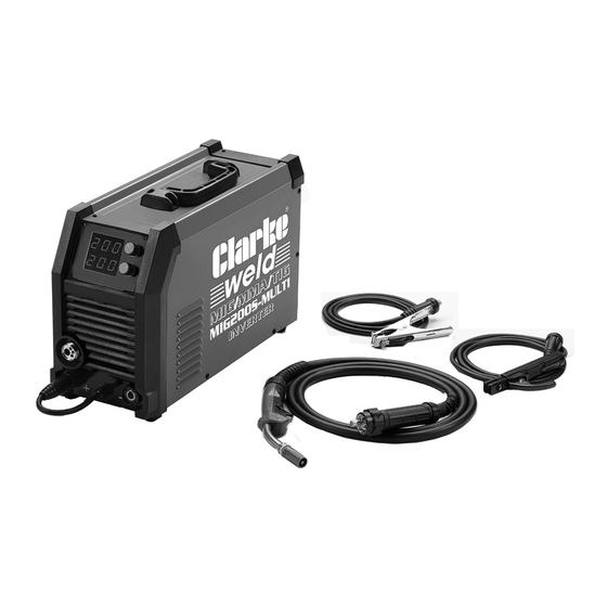
ELECTRICAL CONNECTION WARNING! READ THESE ELECTRICAL SAFETY INSTRUCTIONS THOROUGHLY BEFORE CONNECTING THE PRODUCT TO A POWER SUPPLY. THE INSTALLATION OF THIS APPLIANCE SHOULD BE CARRIED OUT BY A COMPETENT ELECTRICIAN AND BE IN ACCORDANCE WITH CURRENT IEE WIRING REGULATIONS (BS4343). This welder MUST be connected to a 230 Volt, 1 phase 50Hz supply through a suitably rated isolator switch. - Page 14 OVERVIEW The MIG200-S Multi- welder has the following features: LCD colour screen Wire cable feeder interface Amperage adjustment knob Negative pole connection Current adjustment knob Power cable EU torch connector On/off power switch Positive pole connection Gas connection port/Solenoid valve...
- Page 15 • 1 x Wire liner for steel/stainless steel • 1 x Set V-rollers 0.8/1mm • 1 x Wrench (for changing torch tips) When unpacking, any damage or deficiency should be reported to your CLARKE dealer immediately. Parts & Service: 020 8988 7400 / E-mail: Parts@clarkeinternational.com or Service@clarkeinternational.com...
-
Page 16: Mounting The Welding Wire Spool
Spools of welding wire are available from your CLARKE dealer. 1. Open the side panel and remove the locking nut and retaining spring. The retaining locknut nut has a left-hand thread. -
Page 17: Setting The Drive Roller Size
SETTING THE DRIVE ROLLER SIZE 1. Release the tensioning handle and hinge it towards you. 2. Lift up the arm. 3. Unscrew each knurled knob and remove it in order to pull off the guide rollers. • The groove size is stamped on the corresponding side of the roller. -
Page 18: Connecting The Gas Cylinder
NOTE: Correct tension will allow the wire to feed into the torch liner smoothly but will allow the drive roller to slip in the event of a blockage. Adjust the pressure handles so that the pressing force is appropriate so the welding wire is feeding normally and there is no slip on the wire feed rollers RECOMMENDED PRESSURES Wire Dia... - Page 19 CONFIGURING THE MACHINE ATTACHMENTS To prepare the machine for welding it is important that you follow the following procedure. Making sure that the ON/OFF switch, located on the rear panel is in the OFF position, connect the welding leads and gas bottle. MIG WELDING WITH GAS If using 0.9mm flux cored wire, connect the earth...
-
Page 20: Preparing The Workpiece
3. For Flux or MMA welding, select the appropriate welding rod and fit it into the welding rod holder. The following sizes can be used and are available from your CLARKE dealer. WIRE ROD WORKPIECE THICKNESS DIAMETER 0.6 mm... - Page 21 SYNERGIC CONTROL SETTINGS PANEL MENU CONFIGURATION USING THE PANEL MENU FUNCTION SELECTION THE MIG FUNCTION Parts & Service: 020 8988 7400 / E-mail: Parts@clarkeinternational.com or Service@clarkeinternational.com...
- Page 22 MIG WIRE DIAMETER SELECTION AND WELDING WIRE INTERFACE SELECTION 2T/4TS2T/S4T TWIN/SPOT INTERFACE INTERNAL FUNCTIONS OF THE MIG MACHINE Parts & Service: 020 8988 7400 / E-mail: Parts@clarkeinternational.com or Service@clarkeinternational.com...
- Page 23 SINGLE PULSE MIG FUNCTION DOUBLE-PULSE (DP) MIG FUNCTION The 2T/4T setting allows the operator to start the weld simply be pressing the trigger on the torch and then using pre-selectable features such as starting amps, up slope, down slope and ending amps to manage the weld from beginning to end.
- Page 24 INTERNAL FUNCTION OF DOUBLE PULSE MIG SETTING THE MMA FUNCTION SETTING THE LIFT TIG FUNCTION Parts & Service: 020 8988 7400 / E-mail: Parts@clarkeinternational.com or Service@clarkeinternational.com...
-
Page 25: Welding Technique
OPERATING THE WELDER (MIG) CAUTION: THE DUTY CYCLE MUST BE ADHERED TO IN ORDER TO PREVENT THE THERMAL OVERLOAD PROTECTION FROM ACTIVATING 1. Switch on the welder and follow the MIG settings. 2. Cover your face with a suitable welding mask. 3. - Page 26 OPERATING THE WELDER (MMA) WARNING: WHEN WELDING ALWAYS ENSURE THERE IS ADEQUATE VENTILATION IN THE WORK AREA DUE TO TOXIC FUMES. WARNING: DO NOT STRIKE THE ELECTRODE ON THE WORKPIECE, AS THIS MAY DAMAGE THE ELECTRODE. WARNING: WELDING ARCS PRODUCE HARMFUL UV/IR LIGHT WHICH CAN SERIOUSLY DAMAGE YOUR EYES.
- Page 27 OPERATING THE WELDER (TIG WELDING) TIG welding is primarily for very thin materials. It uses a non-consumable tungsten (or tungsten alloy) electrode held in a torch. A shielding gas (100% Argon), is fed through the torch to protect: • The electrode •...
-
Page 28: Lift Tig Welding
LIFT TIG WELDING Before TIG welding, you must obtain the correct torch and a gas cylinder of 100% pure Argon. (see page 37) To prepare the machine for TIG welding and adopt the following procedure. 1. Plug the work clamp lead in to the positve terminal, and secure the work clamp to the workpiece. - Page 29 9. To stop welding, simply remove the torch from the workpiece. 10. Turn off the gas as soon as you finish welding. Notes: • To avoid a visible strike mark on the surface of the workpiece it is advisable to strike the arc in the joint where the mark will be concealed by the weld.
- Page 30 WELDING SETTINGS TABLES L-SHAPED BUTT WELDING Metal Wire Root gap Welding Welding Welding Gas Flow Number thickness diameter current (A) voltage (V) speed (L/min) (mm) (mm) 0.8 - 0.9 60-70 16-16.5 50-60 0.8 - 0.9 75-85 17-17.5 50-60 10-15 0.8 - 0.9 80-90 17-18 50-60...
-
Page 31: Welding Pitfalls
WELDING PITFALLS The arc welding technique is an acquired skill and requires considerable practice before perfect results are obtained. The diagrams below will help to explain the pitfalls in your technique and how to overcome them. ARC TOO SHORT This causes irregular masses of weld to be deposited, with slag contamination on an uneven surface. -
Page 32: Troubleshooting
TROUBLESHOOTING Your CLARKE Welder has been designed to give long and trouble free service. If however, having followed the instructions in this booklet carefully you still encounter problems, the following points should help identify and resolve them. DEFECT CAUSES SUGGESTIONS Spark will not start Bad clamp connection. - Page 33 DEFECT CAUSES SUGGESTIONS Profile defects Welding parameters are Follow basic and general incorrect. welding principles. Pass rate is not related to operating parameter requirements. Electrode not inclined constantly while welding. High Sprays Electrode is too inclined. Make appropriate corrections. Arc is unstable Insufficient current.
- Page 34 DEFECT CAUSES SUGGESTIONS Wire feeds into Wire welded to tip. As previous plus reduce ‘birds nest’ tangle. feed roller pressure. Wire liner damaged Renew wire liner. preventing smooth operation. Loose coils of wire Locking knob too slack. Tighten Locking Knob tangle around slightly.
-
Page 35: Care And Maintenance
To keep the contact tip free from spatter, we recommend the use of anti- spatter spray (6000715) available from your CLARKE dealer. Torch shroud: The torch shroud must also be kept clean and free from spatter. Build-up of spatter inside the gas cup can cause a short circuit at the contact tip which will result in expensive machine repairs. -
Page 36: Component Parts
COMPONENT PARTS Rear plastic cover Power switch Digital PCB Rear panel Middle panel LCD fixed plate Rubber foot Wire feeding door Potentiometer knob Handle assembly Solenoid valve Pull-off Top panel Coupling device base Front plastic cover Middle fixed plate EU torch connector Bottom panel Rectifier PCB board 29 4x4 wire feeder... -
Page 37: Mig Torch Components
MIG TORCH COMPONENTS Sheath Protective spring Contact tip Torch sleeve Diffuser Connector body Swan neck Screw cap Handle EU connector Trigger ARC ACTIVATED HEADSHIELDS These highly popular head-shields activate instantly when the arc is struck and allow you to have both hands free when welding. Model Grinding Solar... -
Page 38: Other Consumables
Argon Gas Regulator 8134140 A Gas Regulator, Arc Activated Headshields, Anti-spatter Spray, Swan Necks, Torch Shrouds and Torch Liner are also available from your CLARKE dealer or our parts division. Parts & Service: 020 8988 7400 / E-mail: Parts@clarkeinternational.com or Service@clarkeinternational.com... - Page 39 DECLARATIONS OF CONFORMITY -UK Parts & Service: 020 8988 7400 / E-mail: Parts@clarkeinternational.com or Service@clarkeinternational.com...
Need help?
Do you have a question about the MIG200-S MULTI and is the answer not in the manual?
Questions and answers