
Related Manuals for Clarke weld MIG250 MULTI


Summary of Contents for Clarke weld MIG250 MULTI
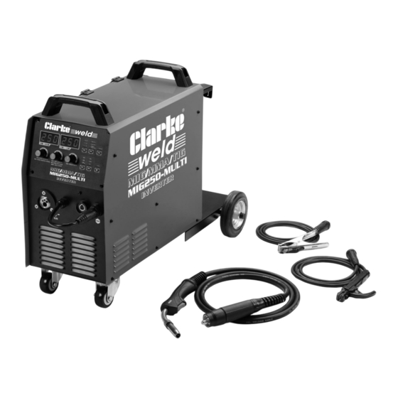
- Page 1 MIG/MMA/TIG INVERTER WELDER MODEL NO: MIG250 MULTI PART NO: 6015607 OPERATION & MAINTENANCE INSTRUCTIONS ORIGINAL INSTRUCTIONS GC06/24...
- Page 2 INTRODUCTION Thank you for purchasing this CLARKE Welder. Before attempting to operate the machine it is essential that you read this manual thoroughly and carefully follow all instructions given. In doing so you will ensure the safety of yourself and that of others around you, and you can also look forward to the welder giving you long and satisfactory service.
- Page 3 PRINCIPLES OF THE MACHINE The MIG250 Multi is an inverter type welding machine, suitable to carry out Gas and No Gas CO welding, MMA, TIG and MIG. The welder is mainly used for CO protected welding which has the advantages of high energy efficiency, strong arc penetration and small welding deformation.
- Page 4 • The unique arc starting and burn back control technology greatly improve the arc starting success rate and achieves high-quality fast spot welding. • The digitally controlled wire feeding system makes the wire feeding more stable. • Synergic control in a MIG welding machine refers to a machine that automatically sets the welding parameters, according to the wire type, diameter and shielding gas.
- Page 5 THE MACHINE RATING PLATE Name/address of manufacturer Energy Supply symbol Model Number Range of Output Part Number Rated No-load Voltage Welding Power Source Conventional Load Voltage British Standards applied Insulation grade Welding Process symbol Rated Supply Voltage Degree of Ingress Protection Rated Maximum Supply Current Welding Current symbol Max Effective Supply Current...
- Page 6 SAFETY PRECAUTIONS FOR ALL TYPES OF WELDING WARNING: AS WITH ALL MACHINERY, THERE ARE CERTAIN HAZARDS INVOLVED WITH THEIR OPERATION AND USE. EXERCISING RESPECT AND CAUTION WILL CONSIDERABLY LESSEN THE RISK OF PERSONAL INJURY. HOWEVER, IF NORMAL SAFETY PRECAUTIONS ARE OVERLOOKED, OR IGNORED, PERSONAL INJURY TO THE OPERATOR MAY RESULT.
- Page 7 atmosphere or where the radiant energy can penetrate to atmospheres containing even minute amounts of trichloroethylene or perchloroethylene. FIRE AND EXPLOSION PREVENTION Causes of fire and explosion are: 1. Combustibles reached by the arc, flying sparks, hot slag or heated material 2.
- Page 8 DO NOT overload arc welding equipment. It may overheat cables and cause a fire. Loose cable connections may overheat or flash and cause a fire. NEVER strike an arc on a cylinder or other pressure vessel. It creates a brittle area that can cause a violent rupture or lead to such a rupture later under rough handling.
- Page 9 persons who will be looking directly at the weld. Others working in the area should wear flash goggles. Before starting to weld, make sure that screen or bay doors are closed. SHOCK PREVENTION Exposed live conductors or other bare metal in the welding circuit, or in unearthed, electrically-LIVE equipment can fatally shock a person whose body becomes a conductor.
- Page 10 SAFETY DEVICES Safety devices such as interlocks and circuit breakers should not be disconnected or shunted out. Before installation, inspection, or service of equipment, shut off all power and remove line fuses (or lock or red-tag switches) to prevent accidental turning ON of power.
- Page 11 5. NEVER use or store in a damp environment. DO NOT EXPOSE TO RAIN. 6. NEVER attempt any electrical or mechanical repair unless your are a qualified technician. If you have a problem with the machine contact your local CLARKE dealer.
- Page 12 SAFETY SYMBOLS The following symbols may be displayed on the machine or its packaging. Read this instruction Do not expose to rain. booklet carefully before use. Wear welding mask Recycle unwanted materials under WEEE Directive Wear protective gloves General Hazard Wear a dust mask Warning;- Magnetic field created (...
- Page 13 ELECTRICAL CONNECTION WARNING! READ THESE ELECTRICAL SAFETY INSTRUCTIONS THOROUGHLY BEFORE CONNECTING THE PRODUCT TO A POWER SUPPLY. THE INSTALLATION OF THIS APPLIANCE SHOULD BE CARRIED OUT BY A COMPETENT ELECTRICIAN AND BE IN ACCORDANCE WITH CURRENT IEE WIRING REGULATIONS (BS4343). IMPORTANT: This product requires a 64A power supply which may...
- Page 14 OVERVIEW OF MACHINE FEATURES THE CONTROL FUNCTIONS The MIG250 Multi-welder is fitted with the following features: 1) TORCH CONNECTION (2) ARC CONTROL This knob controls the output characteristics of the arc. Rotating clockwise, the arc is soft, with deeper penetration and smaller splatter but with weak stability. Rotating anticlockwise, the arc is harder, with better stability, but penetration depth becomes shallower and the splatter increases.
- Page 15 (5) CURRENT DISPLAY The pre-set current is displayed during standby and the actual current is displayed during welding. (6) VOLTAGE DISPLAY The pre-set voltage is displayed during standby and the actual voltage is displayed during welding. (7) INDIVIDUAL / SYNERGIC Individual and synergic modes are available.
- Page 16 (18) COOLING FAN LOOSE ITEMS SUPPLIED The following items are supplied loose with the machine. When unpacking, any damage or deficiency should be reported to your CLARKE dealer immediately. • 1 x MB 25AK welding torch with hose (0.8mm tip fitted) •...
- Page 17 • The welder requires a fused 64A power supply. CONNECTION OF ATTACHMENTS Cables and gas supply must be connected as shown. A wide selection of accessories and consumables are available from your CLARKE dealer (see page 40). Parts & Service: 020 8988 7400 / E-mail: Parts@clarkeinternational.com or Service@clarkeinternational.com...
- Page 18 PREPARING THE MACHINE FOR USE FITTING THE GAS BOTTLE HOLDER AND WHEELS 1. Fit both wheels to the baseplate and secure with the cotter pins supplied. 2. Attach the baseplate/gas bottle support to the underside of the machine using the four bolts supplied.
- Page 19 After the wire diameter is selected, check that the wire diameter matches the size of the wire feeding roller and the welding torch components. Spools of welding wire are available from your CLARKE dealer. 1. Open the side panel and remove the locking nut.
- Page 20 SETTING THE DRIVE ROLLER SIZE 1. Release the tensioning lever to the left and hinge up the tension arm. 2. Unscrew the knurled knob and remove it in order to pull off the guide roller. • The groove size is stamped on the corresponding side of the roller.
- Page 21 RECOMMENDED PRESSURES Wire Dia Recommended Pressure 4 - 5 3 - 4 2 - 3 The wire spool support axle is equipped with a damping adjustment mechanism with an adjustment bolt at its centre. THE MACHINE CONTROL MENU Code Functions Details Description Default...
- Page 22 CONFIGURING THE MACHINE CONNECTIONS To prepare the machine for welding it is important that you follow the following procedure. Making sure that the ON/OFF switch on the rear panel is in the OFF position, connect the welding leads and gas bottle as follows and set the control panel selections as follows.
- Page 23 7. When in MAG mode a mixed gas suitable for MAG welding can be used. If mixing two bottles of gas, a gas mixing valve must be used to deliver an even mixture. WELDING WIRE/ROD The following sizes can be used and are available from your CLARKE dealer. ROD DIAME- WORKPIECE THICK-...
- Page 24 OPERATING THE WELDER (MIG) WARNING: WHEN WELDING ALWAYS ENSURE THERE IS ADEQUATE VENTILATION IN THE WORK AREA DUE TO TOXIC FUMES. WARNING: DO NOT STRIKE THE ELECTRODE ON THE WORKPIECE, AS THIS MAY DAMAGE THE ELECTRODE. WARNING: WELDING ARCS PRODUCE HARMFUL UV/IR LIGHT WHICH CAN SERIOUSLY DAMAGE YOUR EYES.
- Page 25 • DO NOT weld in windy conditions or in an area where ventilation is a problem, or where air flow fluctuates. • ALWAYS keep the wire and nozzle clean...NEVER use rusted wire. • Avoid sharp bends or kinks in the welding hose. Parts &...
- Page 26 OPERATING THE WELDER (MMA/ARC) WARNING: WHEN WELDING ALWAYS ENSURE THERE IS ADEQUATE VENTILATION IN THE WORK AREA DUE TO TOXIC FUMES. WARNING: DO NOT STRIKE THE ELECTRODE ON THE WORKPIECE, AS THIS MAY DAMAGE THE ELECTRODE. WARNING: WELDING ARCS PRODUCE HARMFUL UV/IR LIGHT WHICH CAN SERIOUSLY DAMAGE YOUR EYES.
- Page 27 OPERATING THE WELDER (TIG WELDING) TIG welding is primarily for very thin materials. It uses a non-consumable tungsten (or tungsten alloy) electrode held in a torch. A shielding gas (100% Argon), is fed through the torch to protect: • The electrode •...
- Page 28 TIG WELDING Before TIG welding, you must obtain the correct torch and a gas cylinder of 100% pure Argon from your CLARKE dealer. To prepare the machine for TIG welding, adopt the following procedure. • For good contact, the work clamp must be attached to clean bare metal.
- Page 29 by the argon atmosphere to prevent as far as possible the formation of oxides of its surface. When welding stainless steel and copper, it is often possible to feed in the filler continuously at the edge of the pool. • The arc length generally varies between 3 and 6 mm depending on the type of joint, type and thickness of material and so on.
- Page 30 WELDING SETTINGS TABLES L-SHAPED BUTT WELDING Metal Wire Root gap Welding Welding Welding Gas Flow thickness diameter G (mm) current voltage speed (L/min) (mm) (mm) (cm/min) 0.8 - 0.9 60-70 16-16.5 50-60 0.8 - 0.9 75-85 17-17.5 50-60 10-15 0.8 - 0.9 80-90 17-18 50-60...
- Page 31 ANGLE JOINT (THIN PLATE) Metal Wire Welding Welding Welding Gas Flow thickness diameter current (A) voltage (V) speed (cm/ (L/min) (mm) (mm) min) 0.8-0.9 60-70 16-17 10-15 0.8-0.9 80-90 18-19 0.8-0.9 80 - 90 18-19 10-15 0.8-0.9 90-100 19-20 0.8-0.9 90-100 19-20 10-15...
- Page 32 WELDING PITFALLS The arc welding technique is an acquired skill and requires considerable practice before perfect results are obtained. The diagrams below will help to explain the pitfalls in your technique and how to overcome them. ARC TOO SHORT This causes irregular masses of weld to be deposited, with slag contamination on an uneven surface.
- Page 33 MACHINE ERROR CODES The machine error codes are displayed on the panel. Error Fault Cause Remedy Input over voltage Input voltage too high Check the voltage and correct Input under voltage Input voltage too low Check the voltage and correct. Startup abnormal 1) Torch switch is on 1) Check the torch switch...
- Page 34 Your welder has been designed to give long and trouble free service. If however, having followed the instructions in this booklet carefully you still encounter problems, the following points should help identify and resolve them. For many defects listed the unit is best returned to your. CLARKE dealer . DEFECT CAUSES...
- Page 35 Low power supply voltage. Check the mains distribution system. Welder does not Feed motor defective. Return welder to your CLARKE- feed wire. dealer. Feed motor running Insufficient feed roller Increase roller pressure. but no wire being pressure.
- Page 36 DEFECT CAUSES SUGGESTIONS Poor penetration Low welding current, high Ensure operating welding rate, parameters are regulated and Poor electrode inclination angle improve preparation of work or too far from workpiece. pieces. Profile defects Welding parameters are Follow basic and general incorrect.
- Page 37 To keep the contact tip free from spatter, we recommend the use of anti-spatter spray (6000715) available from your CLARKE dealer. Torch shroud: The torch shroud must also be kept clean and free from spatter. Build-up of spatter inside the gas cup can cause a short circuit at the contact tip which will result in expensive machine repairs.
- Page 38 COMPONENT PARTS Coupling Wire feed door Wheel Pull off connector Door latch Axle Potentiometer knob Left side panel Cylinder support Control panel Handle Bottom panel Display/PCB Hinge Feed holding panel Front cover case Top cover Air damper (U/D) Front panel Cylinder holder 1 Radiator Pos connection strip...
- Page 39 Capacitor PCB Rear panel Air damper (L/R) Wire feed assembly Solenoid valve FRD board Main control board Circuit Breaker IGBT damper Power board Breaker holder FRD damper Insulation post Cooling fan Main Transformer Wire spool holder Fan holder panel Output reactor TORCH COMPONENTS Sheath Protective spring...
- Page 40 6000945 screen 6000910 A Gas Regulator, Arc Activated Headshields, Anti-spatter Spray, Swan Necks, Torch Shrouds and Torch Liner are also available from your CLARKE dealer or our parts division. Parts & Service: 020 8988 7400 / E-mail: Parts@clarkeinternational.com or Service@clarkeinternational.com...
- Page 41 GUARANTEE This CLARKE product is guaranteed against faulty manufacture for a period of 12 months from the date of purchase. Please keep your receipt as proof of purchase. This guarantee is invalid if the product is found to have been abused or tampered with in any way, or not used for the purpose for which it was intended.
- Page 42 DECLARATION OF CONFORMITY - UK Parts & Service: 020 8988 7400 / E-mail: Parts@clarkeinternational.com or Service@clarkeinternational.com...
- Page 43 DECLARATIONS OF CONFORMITY - CE Parts & Service: 020 8988 7400 / E-mail: Parts@clarkeinternational.com or Service@clarkeinternational.com...
Need help?
Do you have a question about the weld MIG250 MULTI and is the answer not in the manual?
Questions and answers