Table of Contents
Advertisement
Quick Links
TECHNICAL MANUAL
KCISA-71 DVR15
KCISA-90 DVR15
KCISA-105 DVR14
IMPORTANT NOTE:
Read this manual carefully before installing or operating your new air conditioning unit.
Make sure to save this manual for future reference.
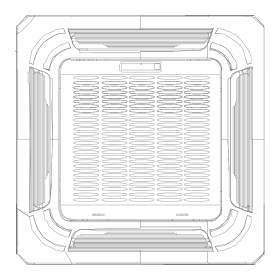
SuperSlim Cassette 840x840
KCISA-105 DTR14
KCISA-125 DVR14
KCISA-140 DVR15
KCISA-140 DTR15
KCISA-160 DTR15
Advertisement
Table of Contents

Related Manuals for Kaysun KCISA-90 DVR15


Summary of Contents for Kaysun KCISA-90 DVR15
- Page 1 TECHNICAL MANUAL SuperSlim Cassette 840x840 KCISA-71 DVR15 KCISA-105 DTR14 KCISA-140 DTR15 KCISA-90 DVR15 KCISA-125 DVR14 KCISA-160 DTR15 KCISA-105 DVR14 KCISA-140 DVR15 IMPORTANT NOTE: Read this manual carefully before installing or operating your new air conditioning unit. Make sure to save this manual for future reference.
-
Page 2: Table Of Contents
Table of Contents Page Specifications ...................... 3 Model Reference ....................4 General Specifications ................... 5 Dimensional Drawings ..................17 Centre of gravity ....................23 Electrical Wiring Diagrams ..................25 Refrigerant Cycle Diagrams .................. 37 Air Velocity and Temperature Distributions ............39 Capacity Tables ....................... -
Page 3: Specifications
Specifications Contents Model Reference ....................4 General Specifications ................... 5 Dimensional Drawings................... 17 Centre of gravity ....................23 Electrical Wiring Diagrams ..................25 Refrigerant Cycle Diagrams .................. 37 Air Velocity and Temperature Distributions ............39 Capacity Tables ....................... 55 Capacity Correction Factor for Height Difference ..........80 Noise Criterion Curves ................... -
Page 4: Model Reference
1. Model Reference Refer to the following table to determine the specific indoor and outdoor unit model number of your purchased equipment. Note: There are two versions of the 36k&48k. Check you are using the right power supply for your model. Power Supply Intake : Outdoor Units Capacity Indoor Unit Model Universal Outdoor Unit Model... -
Page 5: General Specifications
2. General Specifications Indoor model KCIS-71 DR14 Outdoor model KUE-71 DVR14 Power supply (Indoor ) V- Ph-Hz 220~240-1-50 Power Supply (Outdoor) V-Ph-Hz 220~240-1-50 Max. input consumption 3700 Max. current Model ZKFN-45-8-1 Insulation class B(Dayang)/E(Tongda) Indoor fan motor IP rating IP20 Output Capacitor Speed(Hi/Mi/Lo) - Page 6 Number of rows Tube pitch(a)x row pitch(b) 21x22 Fin spacing Outdoor coil Fin type (code) Hydrophilic aluminum Tube outside dia.and type Φ7,Inner groove tube Coil length x height x width 900*609*22+540*609*22 Number of circuits Outdoor air flow m3/h 3500 Outdoor sound pressure level dB(A) Outdoor sound power level dB(A)
- Page 7 Indoor model KCIS-90 DR14 Outdoor model KUE-90 DVR14 Power supply (Indoor ) V- Ph-Hz 220~240-1-50 Power Supply (Outdoor) V-Ph-Hz 220~240-1-50 Max. input consumption 4500 Max. current Model ZKFN-125-8-1 Insulation class Indoor fan motor IP rating IP20 Output Capacitor Speed(Hi/Mi/Lo) r/min 660/600/550 Number of rows Tube pitch(a)x row pitch(b)
- Page 8 Number of rows Tube pitch(a)x row pitch(b) 25.4x22 Fin spacing Outdoor coil Fin type (code) Hydrophilic aluminum Tube outside dia.and type Φ7,Inner groove tube Coil length x height x width 995x762x44 Number of circuits Outdoor air flow m3/h 3800 Outdoor sound pressure level dB(A) Outdoor sound power level dB(A)
- Page 9 Indoor model KCIS-105 DR14 / KCIS-105 DR14 / KUE-105 DVR13 / KUE-105 DTR13 / Outdoor model MO-36N8-Q MO-36N8-R Power supply (Indoor ) V- Ph-Hz 220~240-1-50 220~240-1-50 Power Supply (Outdoor) V-Ph-Hz 220~240-1-50 380~415-3-50 Max. input consumption 5000 5000 Max. current 22.5 10.0 Model ZKFN-125-8-1...
- Page 10 Number of rows Tube pitch(a)x row pitch(b) 25.4x22 25.4x22 Fin spacing Outdoor coil Fin type (code) Hydrophilic aluminum Hydrophilic aluminum Tube outside dia.and type Φ9.52,Inner groove tube Φ9.52,Inner groove tube Coil length x height x width 995x762x44 995x762x44 Number of circuits Outdoor air flow m3/h 4000...
- Page 11 Indoor model KCIS-125 DR14 Outdoor model KUE-125 DVR13 Power supply (Indoor ) V- Ph-Hz 220~240-1-50 Power Supply (Outdoor) V-Ph-Hz 220~240-1-50 Max. input consumption 5000 Max. current 22.5 Model ZKFN-125-8-1 Insulation class Indoor fan motor IP rating IP20 Output Capacitor Speed(Hi/Mi/Lo) r/min 712/648/584 Number of rows...
- Page 12 Number of rows Tube pitch(a)x row pitch(b) 25.4x22 Fin spacing Outdoor coil Fin type (code) Hydrophilic aluminum Tube outside dia.and type Φ9.52,Inner groove tube Coil length x height x width 995x762x22+960x762x22+580x762x22 Number of circuits Outdoor air flow m3/h 4000 Outdoor sound pressure level dB(A) Outdoor sound power level dB(A)
- Page 13 Indoor model KCIS-140 DR14 KCIS-140 DR14 Outdoor model KUE-140 DVR14 KUE-140 DTR14 Power supply (Indoor ) V- Ph-Hz 220~240-1-50 220~240-1-50 Power Supply (Outdoor) V-Ph-Hz 220~240-1-50 380~415-3-50 Max. input consumption 7300 7300 Max. current Model ZKFN-125-8-1 ZKFN-125-8-1 Insulation class Indoor fan motor IP rating IP20 IP20...
- Page 14 Number of rows Tube pitch(a)x row pitch(b) 21x22 21x22 Fin spacing Outdoor coil Fin type (code) Hydrophilic aluminum Hydrophilic aluminum Tube outside dia.and type Φ7,Inner groove tube Φ7,Inner groove tube Coil length x height x width 990*924*66 990*924*66 Number of circuits Outdoor air flow m3/h 5600...
- Page 15 Indoor model KCIS-160 DR14 Outdoor model KUE-160 DTR14 Power supply (Indoor ) V- Ph-Hz 220~240-1-50 Power Supply (Outdoor) V-Ph-Hz 380~415-3-50 Max. input consumption 7500 Max. current Model ZKFN-125-8-1 Insulation class Indoor fan motor IP rating IP20 Output Capacitor Speed(Hi/Mi/Lo) r/min 736/672/608 Number of rows Tube pitch(a)x row pitch(b)
- Page 16 Number of rows Tube pitch(a)x row pitch(b) 25.4x22 Fin spacing Outdoor coil Fin type (code) Hydrophilic aluminum Tube outside dia.and type Φ9.52,Inner groove tube Coil length x height x width 990x1270x44 Number of circuits Outdoor air flow m3/h 7500 Outdoor sound pressure level dB(A) Outdoor sound power level dB(A)
-
Page 17: Dimensional Drawings
3. Dimensional Drawings Indoor Unit Compact Cassette Page 17 ... - Page 18 Super Slim Cassette Model Unit (KBtu/h) inch 6.50 3.15 8.07 1.97 30~36 inch 6.50 3.94 9.65 2.36 42~55 inch 6.50 3.94 11.30 2.36 Page 18 ...
- Page 19 Outdoor Unit KUE-71 DVR14 Page 19 ...
- Page 20 KUE-90 DVR14 , KUE-105 DVR13 . KUE-105 DTR13, KUE-125 DVR13 Page 20 ...
- Page 21 KUE-140 DVR14 , KUE-140 DTR14 Page 21 ...
- Page 22 KUE-160 DTR14 Page 22 ...
-
Page 23: Centre Of Gravity
Centre of gravity KUE-71 DVR14 KUE-90 DVR14 , KUE-105 DVR13 , KUE-105 DTR13 , KUE-125 DVR13 Page 23 ... - Page 24 KUE-140 DVR14 , KUE-140 DTR14 KUE-160 DTR14 Page 24 ...
-
Page 25: Electrical Wiring Diagrams
5. Electrical Wiring Diagrams Indoor unit Abbreviation Paraphrase Yellow-Green Conductor CAP1 Indoor Fan Capacitor FAN1 Indoor Fan LIVE NEUTRAL TO CCM Comm.Bus Central Controller Indoor Room Temperature Coil Temperature of Indoor Heat Exchanger Super High Speed High Speed 24K~55K Page 25 ... - Page 26 4.2 Some connectors introduce: A For ALARM terminal port CN33 1. Provide the terminal port to connect ALARM ,but no voltage of the terminal port , the power from the ALARM system (not from the unit ) 2. Although design voltage can support higher voltage ,but we strongly ask you connect the power less than 24V, current less than 0.5A 3.
- Page 27 B For remote control (ON-OFF) terminal port CN23 and short connector of JR6 1. Remove the short connector of JR6 when you use ON-OFF function; 2. When remote switch off (OPEN) ;the unit would be off; 3. When remote switch on (CLOSE) ;the unit would be on; 4.
- Page 28 C. For new fresh motor terminal port CN8 1. Connect the fan motor to the port , no need care L/N of the motor ; 2. The output voltage is the power supply; 3. The fresh motor can not excess 200W or 1A , follow the smaller one ; 4.
- Page 29 Micro-Switch introduce: A. Micro-switch SW1 is for selection of indoor fan stop temperature (TEL0) when it is in anti-cold wind action in heating mode. Range: 24 C, 15 C, 8 C, According to EEROM setting (reserved for special customizing). B.Micro-switch SW2/SW2-1 is for selection of indoor FAN ACTION if room temperature reaches the setponit and the compressor stops.
- Page 30 C.Micro-switch SW2-2(for some models) is for selection of Breezeless function. Range: OFF, ON. D.Micro-switch SW3 is for selection of auto-restart function. Range: Active, inactive E. Micro-switch SW5 is for setting mode priority of multi connection. Range: Heat, cool. F.Micro-switch SW6 is for selection of temperature compensation in heating mode. This helps to reduce the real temperature difference between ceiling and floor so that the unit could run properly.
- Page 31 G.Micro-switch SW7 is for setting cooling &heating or cooling only. Range: cooling &heating, cooling. H.Micro-switch S1 and dial-switch S2 are for address setting when you want to control this unit by a central controller. Range: 00-63 I. Dial-switch ENC1: The indoor PCB is universal designed for whole series units from 7K to 68K. This ENC1 setting will tell the main program what size the unit is.
- Page 32 Outdoor Unit Abbreviation Paraphrase CAP1, CAP2, CAP3,CAP4 Fan Motor Capacitor FM1,FM2 Outdoor DC Fan FAN1, FAN2 Outdoor AC Fan HEAT, HEAT_Y,HEAT_D CRANKCASE HEATING CT1, CT2 AC Current Detector COMP Compressor L-PRO Low Pressure Switch H-PRO High Pressure Switch PFC Inductor 4-Way Valve TRANS Power Transformer...
- Page 33 KUE-71 DVR14 , KUE-90 DVR14 Page 33 ...
- Page 34 KUE-105 DVR13 ,KUE-125 DVR13 Page 34 ...
- Page 35 KUE-105 DTR13, KUE-160 DTR14 KUE-140 DVR14 OUTDOOR 16022000040450 DC FAN OPTIONAL OPTIONAL CODE PART NAME COMP COMPRESSOR CN32 CN29 CN53 CN30 EEV1 BLACK ELECTRONIC EXPANSION VALVE MAIN CONTROL BOARD OUTDOOR DC BLUE FAN MOTOR HEAT_D CHASSIS HEATER CN12 CN11 CN19 CN21 HEAT_Y CRANKCASE HEATER...
- Page 36 KUE-140 DTR14 16022000039770 V1.0 Page 36 ...
-
Page 37: Refrigerant Cycle Diagrams
6. Refrigerant Cycle Diagrams Pipe Size (Diameter:ø) Piping length (m/ft) Elevation (m/ft) mm(inch) Additional Model Refrigerant Liquid Rated Max. Rated Max. KUE-71 DVR14 15.9(5/8) 9.52(3/8) 5/16.4 50/164 25/82 24g/m (0.26oz/ KUE-90 DVR14 15.9(5/8) 9.52(3/8) 5/16.4 50/164 25/82 For 30k, There is a muffler on the discharge pipe only. ... - Page 38 Pipe Size (Diameter:ø) Piping length (m/ft) Elevation (m/ft) mm(inch) Additional Model Refrigerant Liquid Rated Max. Rated Max. KUE-105 DVR13 15.9(5/8) 9.52(3/8) KUE-105 DTR13 15.9(5/8) 9.52(3/8) KUE-125 DVR13 15.9(5/8) 9.52(3/8) 24g/m (0.26oz/ 5/16.4 75/246.1 30/98.4 KUE-140 DVR14 15.9(5/8) 9.52(3/8) KUE-140 DTR14 15.9(5/8) 9.52(3/8) KUE-160 DTR14...
-
Page 39: Air Velocity And Temperature Distributions
7. Air Velocity and Temperature Distributions Discharge Angle 30° Cooling airflow velocity distributions Cooling temperature distributions Page 39 ... - Page 40 Discharge Angle 30° Heating airflow velocity distributions Heating temperature distributions Page 40 ...
- Page 41 Discharge Angle 60° Cooling airflow velocity distributions Cooling temperature distributions Page 41 ...
- Page 42 Discharge Angle 60° Heating airflow velocity distributions Heating temperature distributions Page 42 ...
- Page 43 Discharge Angle 30° Cooling airflow velocity distributions Cooling temperature distributions Page 43 ...
- Page 44 Discharge Angle 30° Heating airflow velocity distributions Heating temperature distributions Page 44 ...
- Page 45 Discharge Angle 60° Cooling airflow velocity distributions Cooling temperature distributions Page 45 ...
- Page 46 Discharge Angle 60° Heating airflow velocity distributions Heating temperature distributions Page 46 ...
- Page 47 Discharge Angle 30° Cooling airflow velocity distributions Cooling temperature distributions Page 47 ...
- Page 48 Discharge Angle 30° Heating airflow velocity distributions Heating temperature distributions Page 48 ...
- Page 49 Discharge Angle 60° Cooling airflow velocity distributions Cooling temperature distributions Page 49 ...
- Page 50 Discharge Angle 60° Heating airflow velocity distributions Heating temperature distributions Page 50 ...
- Page 51 Discharge Angle 30° Cooling airflow velocity distributions Cooling temperature distributions Page 51 ...
- Page 52 Discharge Angle 30° Heating airflow velocity distributions Heating temperature distributions Page 52 ...
- Page 53 Discharge Angle 60° Cooling airflow velocity distributions Cooling temperature distributions Page 53 ...
- Page 54 Discharge Angle 60° Heating airflow velocity distributions Heating temperature distributions Page 54 ...
-
Page 55: Capacity Tables
8. Capacity Tables Cooling ID WB 16.0 18.0 19.0 22.0 INDOOR (℃) OUTDOOR AIRFLOW DB(℃) ID DB (CMH) 23.0 25.0 27.0 29.0 23.0 25.0 27.0 29.0 23.0 25.0 27.0 29.0 23.0 25.0 27.0 29.0 (℃) 7.35 7.34 7.40 7.46 7.73 7.88 7.88 7.97... - Page 56 7.50 7.50 7.56 7.65 7.88 7.88 7.88 7.97 8.09 8.09 8.09 8.09 8.58 8.58 8.58 8.58 0.73 0.84 0.98 1.00 0.58 0.68 0.77 0.86 0.50 0.60 0.69 0.78 0.34 0.42 0.51 0.60 1.58 1.58 1.58 1.58 1.57 1.57 1.57 1.57 1.57 1.57 1.57...
- Page 57 ID WB 16.0 18.0 19.0 22.0 INDOOR (℃) OUTDOOR AIRFLOW DB(℃) ID DB (CMH) 23.0 25.0 27.0 29.0 23.0 25.0 27.0 29.0 23.0 25.0 27.0 29.0 23.0 25.0 27.0 29.0 (℃) 9.20 9.22 9.31 9.40 9.68 9.89 9.89 9.98 9.90 9.90 9.90 9.90...
- Page 58 9.58 9.67 9.76 9.85 10.07 10.07 10.07 10.16 10.32 10.32 10.32 10.32 10.97 10.97 10.97 10.97 0.78 0.90 1.00 1.00 0.60 0.71 0.83 0.98 0.52 0.63 0.74 0.85 0.33 0.42 0.53 0.64 1.90 1.90 1.90 1.90 1.90 1.90 1.90 1.90 1.90 1.90 1.90...
- Page 59 36k+KUE-105 DVR13 ID WB 16.0 18.0 19.0 22.0 INDOOR (℃) OUTDOOR AIRFLOW DB(℃) ID DB (CMH) 23.0 25.0 27.0 29.0 23.0 25.0 27.0 29.0 23.0 25.0 27.0 29.0 23.0 25.0 27.0 29.0 (℃) 11.05 11.06 11.06 11.18 11.63 11.87 11.87 11.87 11.90 11.90...
- Page 60 11.49 11.49 11.61 11.73 12.08 12.08 12.08 12.20 12.38 12.38 12.38 12.38 13.15 13.15 13.15 13.15 0.73 0.83 1.00 1.00 0.58 0.68 0.76 0.98 0.50 0.60 0.69 0.78 0.34 0.42 0.51 0.60 2.74 2.74 2.74 2.74 2.73 2.73 2.73 2.73 2.72 2.72 2.72...
- Page 61 36k+KUE-105 DTR13 ID WB 16.0 18.0 19.0 22.0 INDOOR (℃) OUTDOOR AIRFLOW DB(℃) ID DB (CMH) 23.0 25.0 27.0 29.0 23.0 25.0 27.0 29.0 23.0 25.0 27.0 29.0 23.0 25.0 27.0 29.0 (℃) 11.05 11.06 11.06 11.18 11.63 11.87 11.87 11.87 11.90 11.90...
- Page 62 11.49 11.49 11.61 11.73 12.08 12.08 12.08 12.20 12.38 12.38 12.38 12.38 13.15 13.15 13.15 13.15 0.73 0.83 1.00 1.00 0.58 0.68 0.76 0.98 0.50 0.60 0.69 0.78 0.34 0.42 0.51 0.60 2.77 2.77 2.77 2.77 2.77 2.77 2.77 2.77 2.76 2.76 2.76...
- Page 63 ID WB 16.0 18.0 19.0 22.0 INDOOR (℃) OUTDOOR AIRFLOW DB(℃) ID DB (CMH) 23.0 25.0 27.0 29.0 23.0 25.0 27.0 29.0 23.0 25.0 27.0 29.0 23.0 25.0 27.0 29.0 (℃) 12.59 12.60 12.72 12.84 13.24 13.51 13.51 13.51 13.57 13.57 13.57 13.57...
- Page 64 13.08 13.08 13.20 13.33 13.78 13.78 13.78 13.78 14.11 14.11 14.11 14.11 14.97 14.97 14.97 14.97 0.73 0.83 1.00 1.00 0.58 0.67 0.76 0.98 0.50 0.60 0.69 0.77 0.34 0.42 0.50 0.59 2.91 2.91 2.91 2.91 2.91 2.91 2.91 2.91 2.90 2.90 2.90...
- Page 65 KCIS-140 DR14 +KUE-140 DVR14 ID WB 16.0 18.0 19.0 22.0 INDOOR (℃) OUTDOOR AIRFLOW DB(℃) ID DB (CMH) 23.0 25.0 27.0 29.0 23.0 25.0 27.0 29.0 23.0 25.0 27.0 29.0 23.0 25.0 27.0 29.0 (℃) 14.70 14.69 14.69 14.84 15.46 15.79 15.79 15.79...
- Page 66 15.33 15.33 15.48 15.63 16.12 16.12 16.12 16.12 16.53 16.53 16.53 16.53 17.54 17.54 17.54 17.54 0.70 0.78 1.00 1.00 0.56 0.64 0.71 0.98 0.49 0.57 0.65 0.72 0.35 0.42 0.49 0.56 3.37 3.37 3.37 3.37 3.35 3.35 3.35 3.35 3.35 3.35 3.35...
- Page 67 KCIS-140 DR14 +KUE-140 DTR14 ID WB 16.0 18.0 19.0 22.0 INDOOR (℃) OUTDOOR AIRFLOW DB(℃) ID DB (CMH) 23.0 25.0 27.0 29.0 23.0 25.0 27.0 29.0 23.0 25.0 27.0 29.0 23.0 25.0 27.0 29.0 (℃) 14.70 14.69 14.69 14.84 15.46 15.79 15.79 15.79...
- Page 68 15.33 15.33 15.48 15.63 16.12 16.12 16.12 16.12 16.53 16.53 16.53 16.53 17.54 17.54 17.54 17.54 0.70 0.78 1.00 1.00 0.56 0.64 0.71 0.98 0.49 0.57 0.65 0.72 0.35 0.42 0.49 0.56 3.45 3.45 3.45 3.45 3.45 3.45 3.45 3.45 3.44 3.44 3.44...
- Page 69 KCIS-160 DR14 +KUE-160 DTR14 ID WB 16.0 18.0 19.0 22.0 INDOOR (℃) OUTDOOR AIRFLOW DB(℃) ID DB (CMH) 23.0 25.0 27.0 29.0 23.0 25.0 27.0 29.0 23.0 25.0 27.0 29.0 23.0 25.0 27.0 29.0 (℃) 15.98 15.98 15.98 16.13 16.80 17.13 17.13 17.13...
- Page 70 16.62 16.62 16.80 16.98 17.46 17.46 17.46 17.46 17.89 17.89 17.89 17.89 19.01 19.01 19.01 19.01 0.70 0.77 1.00 1.00 0.56 0.64 0.71 0.98 0.49 0.57 0.65 0.72 0.35 0.42 0.49 0.56 3.47 3.47 3.47 3.47 3.45 3.45 3.45 3.45 3.45 3.45 3.45...
- Page 71 Heating [SI_Unit] HEATING PERFORMANCE AT INDOOR DRY BULB TEMPERATURE TC:TOTAL CAPACITY IN KILOWATTS (KW) PI:TOTAL POWER IN KILOWATTS (KW) INDOOR OUTDOOR AIRFLOW (CMH) Indoor Conditions (DB °C ) Indoor Conditions (DB °C ) DB(°C) 16.0 20.0 22.0 24.0 16.0 20.0 22.0 24.0 -15.0...
- Page 72 24k+KUE-71 DVR14 [SI_Unit] HEATING PERFORMANCE AT INDOOR DRY BULB TEMPERATURE TC:TOTAL CAPACITY IN KILOWATTS (KW) PI:TOTAL POWER IN KILOWATTS (KW) INDOOR OUTDOOR AIRFLOW (CMH) Indoor Conditions (DB °C ) Indoor Conditions (DB °C ) DB(°C) 16.0 20.0 22.0 24.0 16.0 20.0 22.0 24.0...
- Page 73 KCIS-90 DR14 +KUE-90 DVR14 [SI_Unit] HEATING PERFORMANCE AT INDOOR DRY BULB TEMPERATURE TC:TOTAL CAPACITY IN KILOWATTS (KW) PI:TOTAL POWER IN KILOWATTS (KW) INDOOR OUTDOOR AIRFLOW (CMH) Indoor Conditions (DB °C ) Indoor Conditions (DB °C ) DB(°C) 16.0 20.0 22.0 24.0 16.0 20.0...
- Page 74 KCIS-105 DR14+KUE-105 DVR13 [SI_Unit] HEATING PERFORMANCE AT INDOOR DRY BULB TEMPERATURE TC:TOTAL CAPACITY IN KILOWATTS (KW) PI:TOTAL POWER IN KILOWATTS (KW) INDOOR OUTDOOR AIRFLOW (CMH) Indoor Conditions (DB °C ) Indoor Conditions (DB °C ) DB(°C) 16.0 20.0 22.0 24.0 16.0 20.0 22.0...
- Page 75 KCIS-105 DR14+KUE-105 DTR13 [SI_Unit] HEATING PERFORMANCE AT INDOOR DRY BULB TEMPERATURE TC:TOTAL CAPACITY IN KILOWATTS (KW) PI:TOTAL POWER IN KILOWATTS (KW) INDOOR OUTDOOR AIRFLOW (CMH) Indoor Conditions (DB °C ) Indoor Conditions (DB °C ) DB(°C) 16.0 20.0 22.0 24.0 16.0 20.0 22.0...
- Page 76 [SI_Unit] HEATING PERFORMANCE AT INDOOR DRY BULB TEMPERATURE TC:TOTAL CAPACITY IN KILOWATTS (KW) PI:TOTAL POWER IN KILOWATTS (KW) INDOOR OUTDOOR AIRFLOW (CMH) Indoor Conditions (DB °C ) Indoor Conditions (DB °C ) DB(°C) 16.0 20.0 22.0 24.0 16.0 20.0 22.0 24.0 -15.0 8.18...
- Page 77 KCIS-140 DR14 +KUE-140 DVR14 [SI_Unit] HEATING PERFORMANCE AT INDOOR DRY BULB TEMPERATURE TC:TOTAL CAPACITY IN KILOWATTS (KW) PI:TOTAL POWER IN KILOWATTS (KW) INDOOR OUTDOOR AIRFLOW (CMH) Indoor Conditions (DB °C ) Indoor Conditions (DB °C ) DB(°C) 16.0 20.0 22.0 24.0 16.0 20.0...
- Page 78 KCIS-140 DR14 +KUE-140 DTR14 [SI_Unit] HEATING PERFORMANCE AT INDOOR DRY BULB TEMPERATURE TC:TOTAL CAPACITY IN KILOWATTS (KW) PI:TOTAL POWER IN KILOWATTS (KW) INDOOR OUTDOOR AIRFLOW (CMH) Indoor Conditions (DB °C ) Indoor Conditions (DB °C ) DB(°C) 16.0 20.0 22.0 24.0 16.0 20.0...
- Page 79 KCIS-160 DR14 +KUE-160 DTR14 [SI_Unit] HEATING PERFORMANCE AT INDOOR DRY BULB TEMPERATURE TC:TOTAL CAPACITY IN KILOWATTS (KW) PI:TOTAL POWER IN KILOWATTS (KW) INDOOR OUTDOOR AIRFLOW (CMH) Indoor Conditions (DB °C ) Indoor Conditions (DB °C ) DB(°C) 16.0 20.0 22.0 24.0 16.0 20.0...
-
Page 80: Capacity Correction Factor For Height Difference
9. Capacity Correction Factor for Height Difference Capacity Pipe Length (m) (Btu/h) Cooling 0.914 0.894 0.874 0.944 0.924 0.903 0.883 Indoor Upper than Outdoor 0.975 0.954 0.933 0.912 0.891 Height 0.995 0.984 0.963 0.942 0.921 0.900 differ- 1.000 0.989 0.968 0.947 0.926 0.905... - Page 81 Capacity Pipe Length (m) (Btu/h) Cooling 0.887 0.856 0.824 0.928 0.896 0.864 0.833 Indoor Upper than Outdoor 0.969 0.937 0.905 0.873 0.841 Height 0.995 0.979 0.947 0.914 0.882 0.850 difference 1.000 0.984 0.951 0.919 0.886 0.854 H (m) 1.000 0.984 0.951 0.919 0.886...
- Page 82 0.962 0.943 0.924 0.911 0.975 0.962 0.943 0.924 0.911 Indoor Upper than Outdoor 0.987 0.975 0.962 0.943 0.924 0.911 Height 1.000 0.987 0.975 0.962 0.943 0.924 0.911 differ- 1.000 0.987 0.975 0.962 0.943 0.924 0.911 ence 0.992 0.979 0.967 0.954 0.935 0.917 0.904...
- Page 83 Capacity Pipe Length (m) (Btu/h) Cooling 0.769 0.881 0.839 0.797 0.777 0.919 0.890 0.848 0.806 Indoor Upper than Outdoor 0.785 0.956 0.928 0.899 0.857 0.814 Height 0.793 0.995 0.966 0.937 0.908 0.865 0.822 differ- 0.797 1.000 0.971 0.942 0.913 0.870 0.826 ence 0.797...
- Page 84 0.956 0.933 0.911 0.896 0.970 0.956 0.933 0.911 0.896 Indoor Upper than Outdoor 0.985 0.970 0.956 0.933 0.911 0.896 Height 1.000 0.985 0.970 0.956 0.933 0.911 0.896 differ- 1.000 0.985 0.970 0.956 0.933 0.911 0.896 ence 0.992 0.977 0.963 0.948 0.926 0.904 0.889...
-
Page 85: Noise Criterion Curves
10. Noise Criterion Curves Indoor Unit Notes: -Sound measured at 1.4m away from the noisiest location of the unit. -Data is valid at free field condition -Data is valid at nominal operation condition -Reference acoustic pressure OdB = 20µPa -Sound level will vary depending on a range of factors such as the construction -(acoustic absorption coefficient) of particular room in which the equipment is installed. - Page 86 Page 86 ...
- Page 87 Page 87 ...
- Page 88 Outdoor Unit Note: H= 0.5 × height of outdoor unit Notes: -Sound measured at 1.0m away from the center of the unit. -Data is valid at free field condition -Data is valid at nominal operation condition -Reference acoustic pressure OdB=20µPa -Sound level will vary depending on arrange off actors such as the construction (acoustic absorption coefficient) of particular room in which the equipment is installed.
- Page 89 KUE-90 DVR14 KUE-105 DVR13 KUE-105 DTR13 Page 89 ...
- Page 90 KUE-125 DVR13 KUE-160 DTR14 Page 90 ...
- Page 91 KUE-140 DVR14 KUE-140 DTR14 Page 91 ...
-
Page 92: Electrical Characteristics
11. Electrical Characteristics Capacity (Btu/h) Phase 1-phase 1-phase 1-phase Frequency and Voltage 220-240V, 50Hz 220-240V, 50Hz 220-240V, 50Hz OUDOOR UNIT POWER Power Wiring (mm 3×2.5 3×2.5 3×4.0 Circuit Breaker/ Fuse 25/20 40/30 40/30 Weak Electric Signal) Indoor/Outdoor Connecting Wiring Strong Electric 4×1.0 4×1.0 4×1.0... -
Page 93: Product Features
Product Features Contents 1. Operation Modes and Functions ..............94 Abbreviation ......................94 Safety Features ......................94 Display Function ......................94 Fan Mode ......................... 94 Cooling Mode ......................94 Forced Operation Function ..................97 1.10 Timer Function ......................97 1.11 Sleep function ......................97 1.12 Auto-Restart function .................... -
Page 94: Operation Modes And Functions
1. Operation Modes and Functions • If one temperature sensor malfunctions, the air conditioner continues operation and displays the corresponding error code, allowing for emergency use. Abbreviation • When more than one temperature sensor is malfunctioning, the air conditioner ceases operation. Unit element abbreviations Abbreviation Element... - Page 95 • If the following conditions are satisfied, the increases to 40%; compressor ceases operation. • -When T1-Tsc is higher than 1°C, fan speed • While calculated frequency(fb) is less than minimum increases to 60%; limit frequency(FminC). • -When T1-Tsc is higher than 1.5°C, fan speed •...
- Page 96 1) Reach the configured temperature 2) Auto fan action in heating mode: • If the following conditions are satisfied, the • Rise curve compressor ceases operation. • When T1-Tsc is higher than -1.5°C, fan speed • While calculated frequency(fb) is less than reduces to 80%;...
-
Page 97: Forced Operation Function
Forced auto →Forced cooling →Off • Forced cooling mode: The compressor and outdoor fan continue to run and the indoor fan runs at breeze speed. After running for 30 minutes, the AC will switch to auto mode with a preset temperature of 24°C(76°F). -
Page 98: Auto-Restart Function
not lower than 16°C/60.8°F) every hour. After 2 automatically to 24°C/75°F, fan speed of Auto to hours, the temperature stops decreasing and the save energy (but only if the set temperature is less indoor fan is fixed at low speed. Anti-cold wind than 24°C/75°F). -
Page 99: Installation
Installation Contents Accessories ........................100 1. Installation Overview ....................101 2. Location selection ......................102 3. Indoor Unit Installation ....................103 4. Outdoor unit installation ................... 105 5. Drainage Pipe Installation ................... 106 6. Refrigerant Pipe Installation ..................108 7. Vacuum Drying and Leakage Checking ............... 110 8. -
Page 100: Accessories
Accessories Name Shape Quantity Installation paper template Indoor unit installation (some models) Soundproof/insulation sheath Refrigeration Fittings (some models) Outlet pipe sheath(some models) Outlet pipe clasp(some models) Drainpipe Fittings Drain joint (some models) Seal ring (some models) Remote controller Fixing screw for remote controller holder ST2.9 x 10 Remote controller &... -
Page 101: Installation Overview
1. Installation Overview Install the indoor unit Install the outdoor unit Install the drainpipe Evacuate the refrigeration system Connect the wires Connect the refrigerant pipes Install the front panel Perform a test run Page 101 ... -
Page 102: Location Selection
2. Location selection 2.1 Unit location selection can refer to installation manual. 2.2 DO NOT install the unit in the following locations: Where oil drilling or fracking is taking place. • Coastal areas with high salt content in the air. •... -
Page 103: Indoor Unit Installation
3. Indoor Unit Installation 3.2 Hang Indoor Unit 1. Use the included paper template to cut a rectangular 3.1 Service space for indoor unit hole in the ceiling, leaving at least 1m (39.4”) on all sides. For Compact Cassette, The cut hole size should be 4cm(1.6”) larger than the boby size. - Page 104 For Super-slim Cassette, Refrigerant piping side Drain hose side Adjust the position to ensure the gaps between the indoor unit and the four sides of false ceiling are even. The bottom of the unit should be 24mm / 0.9in(compact cassette) /10 - 25mm (0.4-0.98”)(super-slim cassette) higher than ceiling board.
-
Page 105: Outdoor Unit Installation
4. Outdoor unit installation 4.1 Service space for outdoor unit NOTE FOR NEW HOME INSTALLATION 4.2 Bolt pitch When installing the unit in a new home, the ceiling hooks can be embedded in advance. Make sure that the hooks do not come loose due to concrete shrinkage. -
Page 106: Drainage Pipe Installation
5. Drainage Pipe Installation 4.2 Install Outdoor Unit Install the drainage pipe as shown below and take Fix the outdoor unit with anchor bolts(M10) measures against condensation. Improperly installation could lead to leakage and eventually wet furniture and belongings. >60cm / 23.6” 5.1 Installation principle Ensure at least 1/100 slope of the drainage pipe •... - Page 107 For Vertical drainage pipe (The following table is for reference) Reference Allowable value of inner maximum water Remark pipe diameter of flowrate (l/h) pipe (mm) The correct installation will not cause converse • PVC25 For branch water flow and the slope of the branch pipes can be pipe PVC32 adjusted freely...
-
Page 108: Refrigerant Pipe Installation
6. Refrigerant Pipe Installation ing pipe. Each indoor unit of the system should be installed it. • The installation should be considering the conve- 6.1 Maximum length and drop height • nience for future cleaning. Ensure that the length of the refrigerant pipe, the number of bends, and the drop height between the indoor and outdoor units meets the requirements shown in the following table. - Page 109 4.Cut the selected pipe with pipe cutter 13. Connect the pipe to indoor unit and outdoor unit by using two spanners. Make the section flat and smooth. • Be sure to use two spanners and proper torque to • fasten the nut, too large torque will damage the 90°...
-
Page 110: Vacuum Drying And Leakage Checking
Caution: moisture or leakage in pipeline system and need to go on with drying for half an hour. • The branching pipe must be installed horizontally. An angle of more than 10° may cause malfunction. 3. If the vacuum degree of vacuum pump still could not reach -755mmHg after 1.5 hours of drying, check whether •... -
Page 111: Additional Refrigerant Charge
8. Additional Refrigerant Charge 9. Engineering of Insulation After the vacuum drying process is carried out, the • 9.1 Insulation of refrigerant pipe additional refrigerant charge process need to be performed. 1. Operational procedure of refrigerant pipe The outdoor unit is factory charged with refrigerant. •... -
Page 112: Engineering Of Electrical Wiring
insulation and cause easy aging of the material. The wiring with different voltage should not be in • one wire tube. 9.2 Insulation of drainage pipe Ensure that the color of the wires of outdoor and • the terminal No. are same as those of indoor unit 1. -
Page 113: Panel Installation
11. Panel Installation 2. Adjust the panel by turning it to the direction of arrow shown in figure below so that the ceiling opening is 11.1 Panel Installation of Super-slim Cassette completely covered. 11.1.1 Remove the front grille 1.Push one side of the grille screw cover then remove the grid screw. - Page 114 unit’s height can be adjusted by loosening the upper nut, and adjusting the lower nut. 3. Hang the intake grille on the panel, and then connect the lead connectors of the louver motor and the control box on the panel to the corresponding connectors of the main body.
-
Page 115: Test Operation
11.2.3 Mount the grille Ensure that the buckles at the back of the grille be properly seated in the groove of the panel. 12. Test Operation 1. The test operation must be carried out after the entire installation has been completed. - Page 116 Whether there is vibration or abnormal noise during • operation. Outdoor unit Whether there is vibration or abnormal noise during • operation. Whether the generated wind, noise, or condensed • of by the air conditioner have influenced your neigh- borhood. Whether any of the refrigerant is leaked.
Need help?
Do you have a question about the KCISA-90 DVR15 and is the answer not in the manual?
Questions and answers