Advertisement
Quick Links
INSTALLATION MANUAL
KCI-26DMR11
KCI-35DR11
IMPORTANT NOTE:
Read this manual carefully before installing or operating your new air conditioning unit. Make sure to save this
manual for future reference.
Compact Four-Way Cassette
KCI-52DMR11
KCI-35DVN11
KCI-52DVN10
Advertisement

Subscribe to Our Youtube Channel
Related Manuals for Kaysun KCI-35DR11


Summary of Contents for Kaysun KCI-35DR11
- Page 1 INSTALLATION MANUAL Compact Four-Way Cassette KCI-26DMR11 KCI-52DMR11 KCI-52DVN10 KCI-35DR11 KCI-35DVN11 IMPORTANT NOTE: Read this manual carefully before installing or operating your new air conditioning unit. Make sure to save this manual for future reference.
- Page 2 For R-410 units For R32 units (indoor unit, outdoor unit) KCI-35 DVN11 ✓ ✗ (KCI-35 DR11, KUE-35 DVN11) KCI-52 DVN10 ✓ ✗ (KCI-52 DN10, KUE-52 DVN10) Indoor Units For R-410 units For R32 units KCI-26 DMR11 ✓ ✓ KCI-35 DR11 ✓...
- Page 3 Table of Contents Installation Manual Accessories ............ Safety Precautions ........Installation Overview ....... Indoor Unit Installation ......a. Indoor Unit Parts ........b. Indoor Unit Installation Instructions ..La parte de imagen con el identificador de relación rId13 no se encontró en el archivo. Outdoor Unit Installation ......
- Page 4 Refrigerant Piping Connection ..A. Notes on Pipe Length and Elevation ... B. Refrigerant Piping Connection Instructions ... 17 C. Installation Of The Throttle ....... Wiring ..........a. Power Specifications ....b. Outdoor Unit Wiring ....c. Indoor Unit Wiring ....Air Evacuation ..........
- Page 5 Accessories The air conditioning system comes with the following accessories. Use all of the installation parts and accessories to install the air conditioner. Improper installation may result in water leakage, electrical shock and fire, or cause the equipment to fail. Name Shape Quantity...
- Page 6 Read Safety Precautions Before Installation Incorrect installation due to ignoring instructions can cause serious damage or injury. The seriousness of potential damage or injuries is classified as either a WARNING or CAUTION. accordance with national regulations. WARNING Failure to observe a caution may result in injury or equipment damage. CAUTION WARNING •...
- Page 7 WARNING Any person who is involved with working on or breaking into a refrigerant circuit should hold a specification. Servicing shall only be performed as recommended by the equipment manufacturer. Maintenance and repair requiring the assistance of other skilled personnel shall be carried out under the supervision of the person competent in the use of flammable refrigerants.
- Page 8 Installation Overview INSTALLATION ORDER Install the indoor unit Install the outdoor unit Install the drainpipe (Page 8) (Page 12) (Page 14) Connect the refrigerant pipes Evacuate the refrigeration system Connect the wires (Page 22) (Page 20) (Page 16) Install the front panel Perform a test run (Page 24) (Page 26)
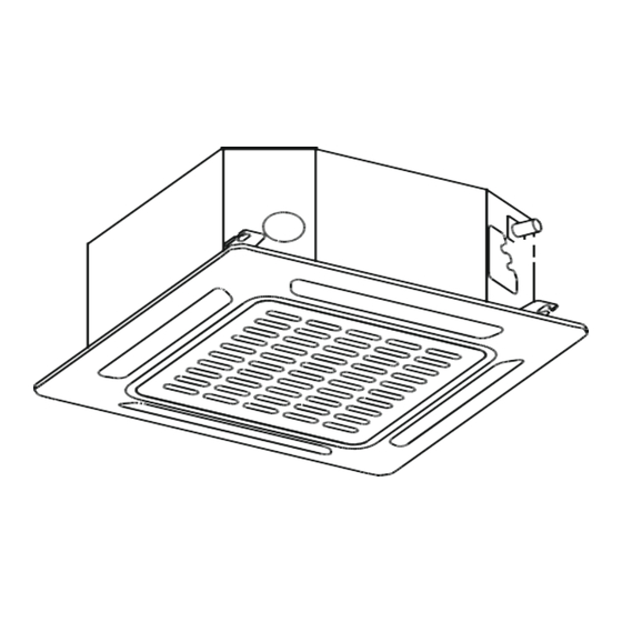
- Page 9 Indoor Unit Installation Indoor Unit Parts Drain pump (within indoor unit) Drain pipe Air outlet Louver Air inlet Display panel Front grille Refrigerant pipe Fig. 4.1 Safety Precautions CAUTION WARNING Securely install the indoor unit on a structure • Install the indoor and outdoor units, cables that can sustain its weight.
- Page 10 Indoor Unit Installation Instructions CAUTION NOTE: Panel installation should be done after DO NOT install the unit in the following piping and wiring. locations: In areas with oil drilling or fracking Step 1: Select installation location In coastal areas with high salt content in The indoor unit should be installed in a location the air that meets the following requirements:...
- Page 11 Step 2: Hang indoor unit. 1. Use the included paper template to cut a rectangular hole in the ceiling, leaving at least 1m (39”) on all sides. The hole will be 60x60cm (23.6x23.6”) big. Be sure to mark the areas where ceiling hook holes will be drilled.
- Page 12 5. Mount the indoor unit. You will need two NOTE: Ensure that the indoor unit is level. The people to lift and secure it. Insert suspension unit is equipped with a built-in drain pump and bolts into the unit’s hanging holes. Fasten float switch.
- Page 13 Outdoor Unit Installation The area must be free of combustible gases o √ Outdoor Unit Installation Instructions and chemicals. o √ The pipe length between the outdoor and Step 1: Select installation location. indoor unit may not exceed the maximum The outdoor unit should be installed in the allowable pipe length.
- Page 14 Split Type Outdoor Unit Drain Joint Installation (Refer to Fig 5.4, 5.5 and Table 5.1) Before bolting the outdoor unit in place, you must install the drain joint at the bottom of the unit. (See Fig. 5.7) 1. Fit the rubber seal on the end of the drain joint that will connect to the outdoor unit.
- Page 15 Drainpipe Installation The drainpipe is used to drain water from the NOTE ON DRAINPIPE INSTALLATION unit. Improper installation may cause unit and When using an extended drainpipe, tighten • property damage. the indoor connection with an additional protection tube to prevent it from pulling CAUTION loose.
- Page 16 3. Using a 65-mm (2.5”) core drill, drill a hole in the wall. Make sure that the hole is drilled at a slight downward angle, so that the outdoor end of the hole is lower than the indoor end by about 12mm (0.5”). This will ensure proper water drainage (See Fig.
- Page 17 Refrigerant Piping Connection Table 7.1: The Maximum Length And Drop Safety Precautions Height Based on Models. (Unit: m/ft.) Type of model Capacity Length of Maximum drop WARNING piping height (Btu/h) All field piping must be completed by a <15K 25/82 10/32.8 North America, Australia and the...
- Page 18 Refrigerant Piping Connection Instructions CAUTION If the outdoor unit is installed higher than the CAUTION indoor unit: The branching pipe must be installed • -It is recommended that vertical suction risers horizontally. An angle of more than 10° may not be upsized. Proper oil return to the cause malfunction.
- Page 19 Step 2: Remove burrs. 6. Place flaring tool onto the form. Burrs can affect the air-tight seal of refrigerant 7. Turn the handle of the flaring tool piping connection. They must be completely clockwise until the pipe is fully flared. Flare removed.
- Page 20 Installation Of The Throttle. (Some Models) CAUTION Ensure to wrap insulation around the piping. • Direct contact with the bare piping may result in burns or frostbite. Make sure the pipe is properly connected. • Over tightening may damage the bell mouth and under tightening may lead to leakage.
- Page 21 Wiring • No other equipment should be connected Safety Precautions to the same power circuit. WARNING • The unit’s power information can be found on the rating sticker on the product. Be sure to disconnect the power supply TAKE NOTE OF FUSE SPECIFICATIONS before working on the unit.
- Page 22 b. Using wire strippers, strip the rubber jacket Indoor Unit Wiring from both ends of signal cable to reveal 1. Prepare the cable for connection about 15cm (5.9”) of the wires inside. a. Using wire strippers, strip the rubber jacket c.
- Page 23 Air Evacuation 4. Turn on the vacuum pump to evacuate the Safety Precautions system. 5. Run the vacuum for at least 15 minutes, or until the Compound Meter reads -76cmHG CAUTION (-1x10⁵Pa). Use a vacuum pump with a gauge reading 6.
- Page 24 Note On Adding Refrigerant CAUTION • Refrigerant charging must be performed after wiring, vacuuming and the leak test. DO NOT exceed the maximum allowable quantity of refrigerant or overcharge the system. • Doing so can damage or impact the unit’s function. •...
- Page 25 Panel Installation Step 2: Install the panel CAUTION Align the indicate "△" on the decoration DO NOT place the panel face down on the panel to the indicate "△" on the unit . floor, against a wall, or on uneven surfaces. Attach the decoration panel to the unit with the supplied screws as shown in figure below.
- Page 26 Step 3: Mount the intake grille. Step 5: Fasten the control box lid with 2 screws. Ensure that the buckles at the back of the grille be properly seated in the groove of the panel. Fig. 10.7 Step 6: Close the intake grille and close the 2 grille hooks.
- Page 27 f. Check to see that the drainage system is Before Test Run unimpeded and draining smoothly. A test run must be performed after the entire g. Ensure there is no vibration or abnormal system has been completely installed. Confirm noise during operation. the following points before performing the test: 5.
- Page 28 Users in European Countries may be required to properly dispose of this unit. This appliance contains refrigerant and other potentially hazardous materials. When disposing of this appliance, the law requires special collection and treatment. DO NOT dispose of this product as household waste or unsorted municipal waste.
- Page 29 Information Servicing (Required for the units adopt R32/R290 Refrigerant only) 1. Checks to the area Prior to beginning work on systems containing flammable refrigerants, safety checks are necessary to ensure that the risk of ignition is minimized. For repair to the refrigerating system, the following precautions shall be complied with prior to conducting work on the system.
- Page 30 7. Ventilated area Ensure that the area is in the open or that it adequately ventilated before breaking into the system or conducting any hot work. A degree of ventilation shall continue during the period that the work is carried out. The ventilation should safely disperse any released refrigerant and preferably expel it externally into the atmosphere.
- Page 31 10. Repairs to sealed components 10.1 During repairs to sealed components, all electrical supplies shall be disconnected from the equipment being worked upon prior to any removal of sealed covers, etc. If it is absolutely necessary to have an electrical supply to equipment during servicing, then a permanently operating form of leak detection shall be located at the most critical point to warn of a potentially hazardous situation.
- Page 32 14. Leak detection methods The following leak detection methods are deemed acceptable for systems containing flammable refrigerants. Electronic leak detectors shall be used to detect flammable refrigerants, but the sensitivity may not be adequate, or may need re-calibration. (Detection equipment shall be calibrated in a refrigerant-free area.) Ensure that the detector is not a potential source of ignition and is suitable for the refrigerant.
- Page 33 When the final OFN charge is used, the system shall be vented down to atmospheric pressure to enable work to take place. This operation is absolutely vital if brazing operations on the pipe-work are to take place. Ensure that the outlet for the vacuum pump is not closed to any ignition sources and there is ventilation available.
- Page 34 f) Make sure that cylinder is situated on the scales before recovery takes place. g) Start the recovery machine and operate in accordance with manufacturer , s instructions. h) Do not overfill cylinders. (No more than 80% volume liquid charge). i) Do not exceed the maximum working pressure of the cylinder, even temporarily.
- Page 35 20. Transportation, marking and storage for units 1. Transport of equipment containing flammable refrigerants Compliance with the transport regulations 2. Marking of equipment using signs Compliance with local regulations 3. Disposal of equipment using flammable refrigerants Compliance with national regulations 4.
Need help?
Do you have a question about the KCI-35DR11 and is the answer not in the manual?
Questions and answers