
Related Manuals for SAJ eManager


Summary of Contents for SAJ eManager
- Page 1 SMART ENERGY CONTROLLER V0.0 USER MANUAL © 2024 Sanjing. All rights reserved.
- Page 2 V0.0 © 2024 Sanjing. All rights reserved.
- Page 3 Preface Thank you for choosing SAJ products. We are pleased to provide you first-class products and exceptional service. This manual provides information about installation, operation, maintenance, troubleshooting and safety. Please follow the instructions of this manual so that we can ensure delivery of our professional guidance and whole-hearted service.
-
Page 4: Table Of Contents
TABLE OF CONTENTS About this Document ......................................6 1.1. Application Scope ........................................6 1.2. Safety .............................................. 6 1.3. Safety Levels ..........................................6 1.4. Symbol Explanation ........................................7 1.5. Safety Instructions ........................................8 1.6. Safe Handling ..........................................8 Product Information ......................................9 2.1. - Page 5 4.2.3. Internal CT connection (current ≤ 63 A) in the three-phase grid ....................27 4.2.4. External CT connection (current > 63 A) in the three-phase grid .................... 28 4.3. Ethernet Connection to the Router (Optional) ..............................29 4.4. Connection to the AC-DC Power Supply Module (Optional) ........................29 Firmware Update ......................................
-
Page 6: About This Document
1. About this Document 1.1. Application Scope This user manual provides instructions and detailed procedures for installing, operating, and maintaining the SAJ product: ⚫ eManager 1.2. Safety CAUTION: ONLY qualified and trained electricians who have read and fully understood all safety regulations contained in this manual can install, maintain, and repair the equipment. -
Page 7: Symbol Explanation
1.4. Symbol Explanation Symbol Description Dangerous electrical voltage This device is directly connected to public grid, thus all work to the device shall only be carried out by qualified personnel. No open flames Do not place or install near flammable or explosive materials. Attention: Install the product out of reach of children. -
Page 8: Safety Instructions
Incorrect operation or misuse of this device may cause personal injury or device damage. This will void the limit warranty and SAJ will not be responsible for the loss caused by those behaviors. -
Page 9: Product Information
2. Product Information 2.1. Application Topology Diagram 2.2. Main Features SAJ eManager smart communication device (hereinafter called the eManager) is applied to the photovoltaic (PV) energy storage system (ESS). ⚫ Energy scheduling management: schedule the energy to the loads, batteries, and the grid based on user requirements. -
Page 10: Package Contents
Easy installation 24-hour local and remote monitoring Remote operation: PV-plant maintenance on App or Web 2.3. Package Contents Document Item Quantity Item Quantity eManager 6-pin connector 12-pin connector Documents ⚫ Quick Guide: 1 ⚫ Commissioning Guide: 1 Antenna AC-DC power supply module (optional) 2.4. - Page 11 Width: 108 mm Depth: 67 mm V0.0 © 2024 Sanjing. All rights reserved.
-
Page 12: Upper View
2.5. Upper view Callout Name Description L1_OUT ONLY applicable in internal CT connection scenario. For connecting the AC power cable for grid phase L1 and supplying power to loads. L2_OUT ONLY applicable in internal CT connection scenario. For connecting the AC power cable for grid phase L2 and supplying power to loads. L3_OUT ONLY applicable in internal CT connection scenario. -
Page 13: Bottom View
Name Description For debugging in maintenance. 12V_IN+ and 12V_IN- eManager backup power supply input; to connect to the DC output of the AC-DC power supply module. RS485 A1 and RS485 B1 For communication with the inverter(s). RS485 A2 and RS485 B2... - Page 14 connected to up to two inverters. DO NO1 and DO COM1 Reserved for future use. DO NO2 and DO COM2 Digital output for connecting to the pump or generator. CT IA* and CT IA For connecting the wires of three CTs. CT IB* and CT IB Note: The asterisk (*) symbol indicates the positive wire of the CT.
-
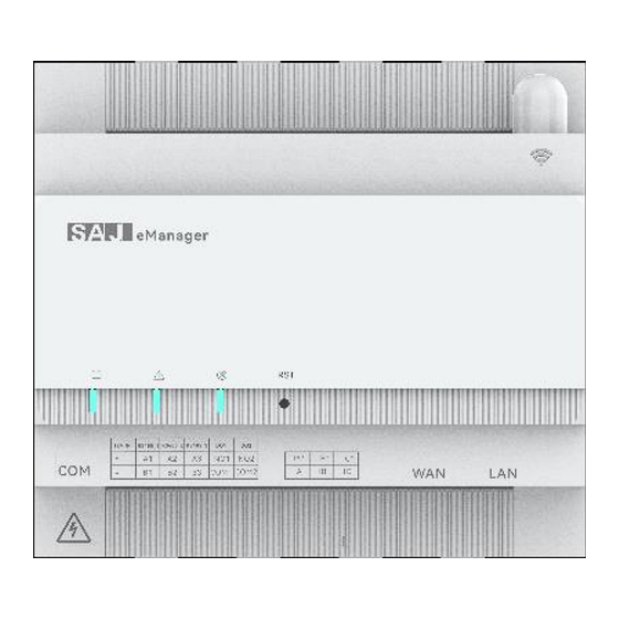
Page 15: Leds
Blinking Green The eManager is connected to the monitoring platform. None The eManager is not connected to the monitoring platform. Reset button You can use a clip to press the button to reset the system. V0.0 © 2024 Sanjing. All rights reserved. -
Page 16: Datasheet
3 years 3. Installation About this task The eManager and the AC-DC power supply module (if available) need to be installed inside the AC distribution box. Before you start Make sure that the AC distribution box meets the requirements: ⚫... - Page 17 Step 1. Install the eManager to the rail. Insert the lower side of the rail into the lower slot on the back of the eManager. Push the eManager upwards until it is secured to the rail. Pivot the eManager until the upper side of the rail is inserted into the upper slot of the eManager.
- Page 18 Step 2. (Optional) Install the AC-DC power supply module to the rail. Pull the tab at the bottom of the module downwards. Insert the upper side of the rail into the upper slot on the back of the module. Pivot the module until the lower side of the rail is inserted into the lower slot of the module. Push the tab at the bottom of the module upwards to secure module to the rail.
- Page 19 Step 3. Install the antenna to the eManager. Remove the stud cap on the upper right corner of the eManager. Install the antenna to the stud and tighten it. V0.0 © 2024 Sanjing. All rights reserved.
-
Page 20: Electrical Connection
⚫ HS2-(3K-6K)-S2 Connect the communication cables from the RS485 port on the inverter to the corresponding terminals on the eManager. If the RS485 port is not available on the inverter, use the EMS/Meter port. From the RS485 or EMS/Meter port on the inverter... -
Page 21: Internal Ct Connection (Current ≤ 63 A) In The Single-Phase Grid
4.1.1. Internal CT connection (current ≤ 63 A) in the single-phase grid If the current exceeds 63 A, use the external CT connection manner. Notes: ⚫ For detailed connection on the inverter side, refer to section 4.1 "RS485 Connection (up to 6 inverters)". ⚫... -
Page 22: External Ct Connection (Current > 63 A) In The Single-Phase Grid
4.1.2. External CT connection (current > 63 A) in the single-phase grid Notes: ⚫ You can use 100A/50mA or 250A/50mA CTs, depending on the plant capacity. (Plant capacity = The greater value of the total inverter power or the total on-grid load power) ⚫... -
Page 23: Internal Ct Connection (Current ≤ 63 A) In The Three-Phase Grid
4.1.3. Internal CT connection (current ≤ 63 A) in the three-phase grid If the current exceeds 63 A, use the external CT connection manner. Notes: ⚫ For detailed connection on the inverter side, refer to section 4.1 "RS485 Connection (up to 6 inverters)". ⚫... -
Page 24: External Ct Connection (Current > 63 A) In The Three-Phase Grid
4.1.4. External CT connection (current > 63 A) in the three-phase grid Notes: ⚫ You can use 100A/50mA or 250A/50mA CTs, depending on the plant capacity. (Plant capacity = The greater value of the total inverter power or the total on-grid load power) ⚫... -
Page 25: Lan Connection (Up To 10 Inverters)
H2-(10K-30K)-(T2, T3) ⚫ Connect all the communication cables from the LAN port on the eManager and the LAN port on the inverter to a switch. 4.2.1. Internal CT connection (current ≤ 63 A) in the single-phase grid If the current exceeds 63 A, use the external CT connection manner. -
Page 26: External Ct Connection (Current > 63 A) In The Single-Phase Grid
4.2.2. External CT connection (current > 63 A) in the single-phase grid Notes: ⚫ You can use 100A/50mA or 250A/50mA CTs, depending on the plant capacity. (Plant capacity = The greater value of the total inverter power or the total on-grid load power) ⚫... -
Page 27: Internal Ct Connection (Current ≤ 63 A) In The Three-Phase Grid
4.2.3. Internal CT connection (current ≤ 63 A) in the three-phase grid If the current exceeds 63 A, use the external CT connection manner. Notes: ⚫ For detailed connection on the inverter side, refer to section 4.2 "LAN Connection (up to 10 inverters)". ⚫... -
Page 28: External Ct Connection (Current > 63 A) In The Three-Phase Grid
4.2.4. External CT connection (current > 63 A) in the three-phase grid Notes: ⚫ You can use 100A/50mA or 250A/50mA CTs, depending on the plant capacity. (Plant capacity = The greater value of the total inverter power or the total on-grid load power) ⚫... -
Page 29: Ethernet Connection To The Router (Optional)
LAN port the router 4.4. Connection to the AC-DC Power Supply Module (Optional) If the eManager needs to work during the off-grid time, the ESS can provide the power supply to the eManager through the AC-DC power supply module. Connect the cables from the AC-DC power supply module to the inverter and the eManager, as listed below:... - Page 30 Step 3. Select Inverter or Communication module to display corresponding devices. Note: No need to upgrade the battery. V0.0 © 2024 Sanjing. All rights reserved.
- Page 31 Alternatively, you can locate the required device based on its SN: Click Filter to display the detailed search box. Input the SN and click OK. Note: For batch upgrade, separate the device SNs by using the comma (,). V0.0 © 2024 Sanjing. All rights reserved.
- Page 32 Step 4. Select the required device and click Device upgrade. Step 5. Select the firmware version: To upgrade to the up-to-date firmware version, select the latest firmware version; to upgrade to a specific firmware version, click Upload local upgrade package to upload the local upgrade file. Set the upgrade time: Depending on your needs, upgrade the firmware right now or in a specific time: Upgrade now: Select Instant distribution and click Upgrade Now.
- Page 33 Step 6. Click Upgrade record and then click the icon under Operation to view the upgrade details (including the upgrade status and result). Upgrade status: Being upgraded V0.0 © 2024 Sanjing. All rights reserved.
-
Page 34: Local Upgrade (Web Page And App) (Bluetooth Connection)
---End 5.2. Local Upgrade (Web page and App) (Bluetooth Connection) Before you start The firmware package has been uploaded. If any question, contact SAJ technical support. Procedure Step 1. Log in to the eSAJ All-In-One Smart EMS platform at https://esaj-home.saj-electric.cn/system/account. - Page 35 Step 2. Log in to the eSAJ Home App. Select the required EMS device (the suffix is last five number of the EMS device SN). Tap Firmware Update and then tap the device to be upgraded. V0.0 © 2024 Sanjing. All rights reserved.
-
Page 36: After Upgrade
Step 3. On Firmware Update, select the latest version and tap Update. On the displayed dialog box, tap OK to confirm the upgrade. During the upgrade, the Bluetooth connection will be disconnected. After the upgrade, reconnect the Bluetooth and tap Firmware Update again to check the upgrade result. ---End 5.3. -
Page 37: Commissioning By The App
6. Commissioning by the App The eSAJ Home App can be used for both nearby and remote monitoring. It communicates with different devices through Bluetooth or Ethernet connection. The detailed operations on the App might vary, depending on the version you are using. 6.1. -
Page 38: Performing The Initialization Settings
— No account? Apply for a new account for login. Click the three-dot icon on the top right corner. Choose the language and network node based on your needs. Click Register. Choose whether you are an owner, an installer, or a distributor. Note: For commissioning convenience, it is suggested that the install apply for the owner account. - Page 39 On the Service interface, select Remote Configuration. Tap Bluetooth and then Next. XXXXX Choose your EMS device (eManager: ) from the device list. Then, tap Initialization. XXXXX Note: are the last five number of the serial number (SN) of your EMS device.
- Page 40 ⚫ Make sure that each inverter is added in the proper RS485 connection setting area. For example, the inverter connected to the RS485_A1 and RS485_B1 ports of the eManager must be added to the RS485_1 setting area. ⚫ If one inverter is mistakenly added, you can tap remove it.
- Page 41 Wiring method Set the wiring method and CT connection details. ⚫ If external 100A/50mA CT connection is used, set CT Transformation Ratio to 10. ⚫ If external 250A/50mA CT connection is used, set CT Transformation Ratio to 25. Policy configuration — Creating policy templates Verify that Current policy is set to Peak clipping and valley filling by default.
- Page 42 Time-sharing policy: You can set a maximum of 12 ⚫ periods for one day and set different work statuses (charging, discharging, and standby) for these periods. Notes: The charging and discharging power set here is for the whole system. If Self-consumption mode is enabled, the inverter works in the self-consumption mode in standby status.
- Page 43 period one by one; or you can use batch settings to select one certain policy template for periods of a same type. After all the policy configuration is set, tap Next Step to go to next configuration. Export limitation settings Depending on your needs, enable Export limitation and set Selling Power Limit.
- Page 44 Safety settings Select Country and Grid Compliance. Tap AUTO TIME SYNC to set Device time to your current time zone. 10. After the initialization is completed, view the EMS settings for double check, especially check the followings: Tap Network configuration and verify that it is set to up. Note: If the Wi-Fi signal strength is lower than -70 dBm, it is recommended to use Ethernet connection manner.
-
Page 45: Creating A Plant
6.4. Plant Creating a On the Management page, click the icon on the top right corner. Select Create Plant for Owner. Apply for an account for the end user. V0.0 © 2024 Sanjing. All rights reserved. - Page 46 Configure the plant details based on your actual conditions. Set the name, capacity, country or region, location, detailed address, user type, number of components, and PV panel azimuth. Scan the EMS SN. Double check whether all devices added to this EMS are displayed.
-
Page 47: Appendix
Check the product warranty conditions and terms on the SAJ website: https://www.saj-electric.com/ 7.3. Contacting Support Guangzhou Sanjing Electric Co., Ltd. Address: SAJ Innovation Park, No.9, Lizhishan Road, Guangzhou Science City, Guangdong, P.R.China. Postcode: 510663 Website: https://www.saj-electric.com/ Technical Support & Service...
Need help?
Do you have a question about the eManager and is the answer not in the manual?
Questions and answers