Table of Contents
Advertisement
Advertisement
Table of Contents

Subscribe to Our Youtube Channel
Related Manuals for SAJ 8000m Series


Summary of Contents for SAJ 8000m Series
- Page 1 8000m Series Compact AC Drive User Manual Version Code :8000m-E-602000600-1705...
-
Page 2: Preface
8000m Series Preface First of all, thank you for purchasing 8000m Series Compact AC Drive! This user manual introduces how to use 8000m series variable frequency drives (VFDs) properly. Please read this user manual carefully before carrying out works such as installation, commissioning, maintenance, etc. -
Page 3: Table Of Contents
Preface ....................- 1 - SAFETY INSTRUCTION ..............- 5 - Manual Conventions ................- 9 - Chapter 1 Introduction to the 8000m series VFD ......- 10 - 1.1 Model Description ..............- 10 - 1.2 Namplate Example ..............- 10 - 1.3 Model Table ................ - Page 4 8000m Series Chapter 5 Function Parameter Description ........- 56 - 5.1 F0 Group—Basic Function ............- 56 - 5.2 F1 Group: Start and Stop Parameters ......... - 66 - 5.3 F2 Group: Motor Parameters ............. - 70 - 5.4 F3 Group: Vector Control Parameters ........- 73 - 5.5 F4 Group: V/F Control Parameters ..........
- Page 5 8000m Series 8.3 Frame Format ................- 139 - 8.4 Protocol Function ..............- 141 - 8.5 Note ..................- 145 - 8.6 CRC Checksum ................ - 146 - 8.7 Example ..................- 147 - 8.8 Data Address Table of Function Code ........- 149 -...
-
Page 6: Safety Instruction
8000m Series SAFETY INSTRUCTION Read this user manual thoroughly before installation, operation, maintenance or inspection of the variable frequency drive (VFD). In this manual, safety instructions are classified as “WARNING” or “CAUTION”. WARNING: Indicate a potentially dangerous situation which, if not avoided, can result in death or serious injury to personnel. - Page 7 8000m Series ■ Wiring ◎Ensure only qualified electrical engineering personnel for wiring work . Otherwise it can cause an electrical shock or damage to the VFD. ◎Make sure VFD is isolated from power supply by the circuit breaker. Otherwise it may cause electrical shock or a fire.
- Page 8 8000m Series ■ Operating ◎It is only allowed to power on the VFD after the wirng is finished and its cover is reinstalled. It is strictly prohibit to remove the cover of VFD while power is on, otherwise it may cause electric shock.
- Page 9 8000m Series ■ Maintenance ◎Never touch the VFD the connection terminals when power is on. Otherwise it may cause an electrical shock. ◎Only qualified electrical engineering personnal can be authorized to do the jobs of maintenance, checking, or parts replacement.
-
Page 10: Manual Conventions
8000m Series Manual Conventions In this manual we refer to 8000m Series Variable Frequency Drives as: drive, inverter, VFD, 8000m, 8000m drive, AC drive or 8000m Series Compact AC Drive. - 9 -... -
Page 11: Chapter 1 Introduction To The 8000M Series Vfd
8000m Series Chapter 1 Introduction to the 8000m series VFD 1.1 Model Description 1.2 Namplate Example - 10 -... -
Page 12: Model Table
8000m Series 1.3 Model Table Rated Output Rated Input Rated Output Motor Power Drive Model Power kW Current A Current A Single-phase 220V±15% 8000m-2SR4GH 8000m-2SR75GH 0.75 0.75 8000m-2S1R5GH 14.2 8000m-2S2R2GH Three-phase 380V±15% 8000m-4TR75GH 0.75 0.75 8000m-4T1R5GH 8000m-4T2R2GH 1.4 Specifications Control Characteristics... - Page 13 8000m Series Input & Output Characteristics Start Frequency 0.01~10Hz Rated Input Voltage 220V/380V ± 15% Rated Input 50/60Hz,fluctuation range:±5% Frequency Frequency Reference Analog signals: max. frequency × 0.1%; Digital setting:0.01Hz Resolution Output Voltage 0: rated input voltage Output Frequency 0.00~600Hz...
- Page 14 8000m Series Swing Frequency Suitable for some textile and chemical fiber machines by Function programmable controlling of the triangular frequency references. Automatic Voltage Regulation (AVR), automatically keep the AVR Function output voltage constant when power supply is not stable. Stall Prevention automatically control the decelerating procedure...
-
Page 15: Dimensions And Sizes
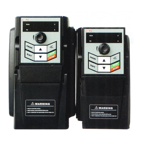
8000m Series 1.5 Dimensions and Sizes Dimensions Drawing Single phase 220V 1.5-2.2kW and 3-phase380V 0.75kW-2.2kW Single phase 220V 0.4-0.75kW - 14 -... -
Page 16: Keypad Tray Dimensions
8000m Series Diameter of Dimensions(mm) Voltage Drive Model installation Class hole(mm0 8000m-2SR4GH 81.3 67.4 151.3 132.8 Single 8000m-2SR75GH Phase 8000m-2S1R5GH 220V 8000m-2S2R2GH Φ5 8000m-4TR75GH 99.3 86.8 164.7 147.4 Three Phase 8000m-4T1R5GH 380V 8000m-4T2R2GH 1.6 Keypad Tray Dimensions - 15 -... -
Page 17: Rs485 Interface
8000m Series 1.7 RS485 Interface Terminal Symbol Function Specifications Positive pole of differential signal Standard Negative pole of differential signal RS485 Positive pole of extension power (+5V) interface Negative pole of extension power 1.8 Braking Resistor Selection Table Recommended Recommended Power... -
Page 18: Chapter 2 Installation And Wiring
8000m Series Chapter 2 Installation and Wiring 2.1 Installation 2.1.1 Installation Environment ◎The ambient temperature exerts great influences on the service life of the VFDs and is not allowed to exceed the specified temperature range (-10℃ to 40℃ ). ◎A VFD is easy to generate large amount of heat during operation. Thus VFDs should be mounted vertically with screws on the surface of incombustible objects, with sufficient spaces nearby for heat sinking. - Page 19 8000m Series Multi Drive (up and down) Installation When take up and down installation, air deflector should be installed between upper and lower VFD, as illustrated below. - 18 -...
- Page 20 8000m Series 2.1.4 Electric Elements and Material Peripheral Electric Elements Connection Diagram - 19 -...
- Page 21 8000m Series 2.1.5 Descriptions of External Electrical Parts Name Mounting Location Function Circuit Disconnect the power supply when the Front end of input circuit Breaker backward equipment is over current. Power ON/OFF of inverter. Do not use the Between the circuit breaker Contactor contactor as the switch of inverter.
- Page 22 8000m Series Conducting Conducting Conducting Circuit Recommend Wire of Main Wire of Main Wire of Inverter Model Breaker ed Contactor Circuit at the Circuit at the Control (MCCB) (A) Input Side Input Side Circuit 8000m-2SR75GB 8000m-2SR75GB 8000m-2S1R5GB 8000m-2S2R2GB 8000m-4TR75GB 8000m-4T1R5GB 8000m-4T2R2GB 2.1.7 Table of...
-
Page 23: Wiring
8000m Series 2.2 Wiring 2.2.1 Wiring Diagram Note: 1. ◎ refers to terminals of main circuit; ○ refers to terminals of control circuit. 2. For 220V single phase inverter, the terminals of main circuit are R and S. - 22 -... - Page 24 8000m Series 2.2.2 Main Circuit Terminals Terminals Descriptions AC power inputterminals. R, S and T 3-phase: R, S and T Single phase: R and S U, V and W AC power output terminals (For connecting motor) DC bus terminal of positive pole...
- Page 25 8000m Series 2.2.4 Precautions on Main Circuit Wiring 2.2.4.1 Terminals R, S and T The wiring at the input side of inverter has no phase sequence requirement. When input single-phase power, use terminal R and T. 2.2.4.2 DC Bus Terminals (+) and PB of Brake Resistor The (+) terminal of DC bus have residual voltage right after power-off.
- Page 26 8000m Series 2.2.5 Control Circuit Terminals Symbol Terminal Name Function Do not connect additional power source directly. Multi-functional digital A digital input is ON when it is connected to M1~M4 input terminals GND, and will be OFF when it is opened.
-
Page 27: Chapter 3 Keypad Operation
8000m Series Chapter 3 Keypad Operation 3.1 Keypad Operation 3.1.1 Keypad Outline 3.1.2 Keys Description Symbol Key Name Function Description PRGM Program/ Exit key Enter or exit of menu, parameter modification Enter key Progressively enter menu and confirm parameter Progressively increase data or function codes. -
Page 28: Operation Details
8000m Series Use it to select displayed parameters cyclically during Shift key running or stop status. In parameter setting mode, press << this key to select the bit to be modified. Run/Stop/Reset For start, stop and reset operation, depends on control RUN/STOP mode setting. - Page 29 8000m Series For example: Change function code F1.01 from 0.50Hz into 05.00Hz as shown in the following flow chart: Flow Chart of Parameter Setting Under the third-class menu, if the parameter has no flickering bit, it means that the function code cannot be modified. The possible reasons include: (1) The parameter of this function code can’t be modified, such as actually detected...
- Page 30 8000m Series 3.2.2 Fault Reset When inverter malfunction occurs, it will display the relative fault information. Use the RUN/STOP key or terminals (determined by F5 group) to reset the fault. After fault reset, inverter is at stand-by status. If not reset when inverter is at fault status, it will keep operation protection status and cannot run.
-
Page 31: Chapter 4 Function Parameter Table
8000m Series Chapter 4 Function Parameter Table 4.1 Symbol Conventions: “○”: The parameters can be modified both at stop and running status. “◎”: The parameters cannot be modified at running status. “●”: The parameters are actual-detecting record value or factory preserved settings and cannot be modified. - Page 32 8000m Series Function Minimum Factory Modifica- Function Descriptions Code Unit Setting tion Type 3: Reserved 4: Reserved 5: Reserved Settings of master 6: Multi-function digital input F0.03 ● frequency source X terminals 7: PLC 8: PID 9: Communication interface Settings of 0: AVI terminal F0.04...
- Page 33 8000m Series Function Minimum Factory Modifica- Function Descriptions Code Unit Setting tion Type Upper limit F0.12 F0.14~ F0.10 0.01Hz 50.00Hz ○ frequency F0.13 Reserved Lower limit F0.14 0.00Hz~ F0.12 0.01Hz 0.00Hz ○ frequency 0 : Running at lower limit The function of frequency F0.15...
- Page 34 8000m Series Function Minimum Factory Modifica- Function Descriptions Code Unit Setting tion Type F0.22~ Reserved F0.24 Cooling fan 0: Keep running when power on F0.25 ○ running method 1: Reserved F1 Group: Start and Stop Parameters 0:Start directly F1.00 Start mode 1:DC braking first and then start ●...
- Page 35 8000m Series Function Minimum Factory Modifica- Function Descriptions Code Unit Setting tion Type option when power 1: Enabled F1.12 ~ Reserved F1.17 Wake-up time F1.18 0.0~3600s 0.1s 0.0s ○ delay Restart option after 0: Disabled F1.19 ○ power-off 1:Enabled Waiting time of F1.20...
- Page 36 8000m Series Function Minimum Factory Modifica- Function Descriptions Code Unit Setting tion Type Motor stator F2.06 0.001~65.53Ω 0.001Ω ○ resistance Motor rotator F2.07 0.001~65.53Ω 0.001Ω ○ resistance Motor stator F2.08 0.1~6553mH 0.1mH ○ inductance Motor rotator F2.09 0.1~6553mH 0.1mH ○...
- Page 37 8000m Series Function Minimum Factory Modifica- Function Descriptions Code Unit Setting tion Type F3.08~F Reserved 3.09 0: Not detect 1: Effective during running and keep running after alarm 2: Effective during running and stop after alarm (fault Pre-alarm option F3.10 code:E023) ○...
- Page 38 8000m Series Function Minimum Factory Modifica- Function Descriptions Code Unit Setting tion Type F4.04 V/F voltage 1 0.0%~100.0% 0.10% 0.00% ● F4.05 V/F frequency 2 F4.03~F4.07 0.01Hz 25.00Hz ● F4.06 V/F voltage 2 0.0%~100.0% 0.10% 50.00% ● F4.07 V/F frequency 3 F4.05~motor rated frequency...
- Page 39 8000m Series Function Minimum Factory Modifica- Function Descriptions Code Unit Setting tion Type F5 Group: Input Terminals Parameters 0:Invalid 1:Forward run (FWD) 2:Reverse run (REV) M1 terminal 3:3-wire control F5.00 ● function 4:Forward jog run (FJOG) 5:Reverse jog run (RJOG)
- Page 40 8000m Series Function Minimum Factory Modifica- Function Descriptions Code Unit Setting tion Type 24: Simple PLC pause 25: PID pause 26: Swing frequency pause (maintain at current frequency) F5.04 Reserved 27: Reset after swing frequency pause (reset to central frequency)
- Page 41 8000m Series Function Minimum Factory Modifica- Function Descriptions Code Unit Setting tion Type Setting value F5.14 corresponding to -100.0%~100.0% 0.10% 0.00% ○ AVI lower limit F5.15 AVI upper limit 0.00V~10.00V 0.01V 10.00V ○ Setting value F5.16 corresponding to -100.0%~100.0% 0.10% 100.00%...
- Page 42 8000m Series Function Minimum Factory Modifica- Function Descriptions Code Unit Setting tion Type 8: Lower limit frequency reached Relay 1 output 9:Frequency setting value less F6.02 ○ selection than lower limit frequency 10:FDT reached 11:Accumulative running time reached 12:PLC cycle completed 13: VFD overload pre-alarm F6.03~F...
- Page 43 8000m Series Function Minimum Factory Modifica- Function Descriptions Code Unit Setting tion Type F6.10~F Reserved 6.13 0:Running frequency 1:Setting frequency 2:DC bus voltage 3:Output current User defined 4:Output voltage output 5:Sign of start and stop status F6.14 variability option 6:Sign of control status...
- Page 44 8000m Series Function Minimum Factory Modifica- Function Descriptions Code Unit Setting tion Type F7.01~F Reserved 7.03 0:Only valid for keypad setting 1:Valid for both keypad setting and terminals setting RUN/STOP key F7.04 2:Valid for both keypad setting ○ stop function...
- Page 45 8000m Series Function Minimum Factory Modifica- Function Descriptions Code Unit Setting tion Type 1~0xFFFF BIT0:AVI value BIT1: Reserved Running BIT2:Reserved F7.07 status display BIT3: Motor overload ratio ○ selection 2 BIT4: Inverter overload ratio BIT5:Running time BIT6:Counting meter value BIT7~BIT15: Reserved...
- Page 46 8000m Series Function Minimum Factory Modifica- Function Descriptions Code Unit Setting tion Type F8 Group: Auxiliary Function Parameters Jog running F8.00 0.00~F0.10 0.01Hz 5.00Hz ○ frequency Jog running F8.01 0.1~3600s 0.1s ○ acceleration time Jog running F8.02 0.1~3600s 0.1s ○...
- Page 47 8000m Series Function Minimum Factory Modifica- Function Descriptions Code Unit Setting tion Type Braking threshold 115.0~140.0% (Standard DC F8.15 0.10% 120.00% ○ voltage bus voltage) Speed display F8.16 0.1~999.9% 0.10% 100.00% ○ coefficient Option as running 0:Keep running 8.17 ○...
- Page 48 8000m Series Function Minimum Factory Modifica- Function Descriptions Code Unit Setting tion Type 0:Keypad (F9.01) 1:Analog terminal AVI 2:Reserved F9.00 PID setting source ○ 3:Communication interface 4:Muli-function digital input terminals F9.01 PID preset value 0.0%~100.0% 0.10% 0.00% ● 0:Analog terminal AVI...
- Page 49 8000m Series Function Minimum Factory Modifica- Function Descriptions Code Unit Setting tion Type PID wake-up F9.13 0.0~100.0% 0.10% 0.00% ○ threshold PID wake-up F9.14 detecting delay 0.0~3600.0s 0.1s 3.0s ○ time Lower retaining F9.15 frequency of PID 0.00Hz~20.00Hz 0.01Hz 10.00Hz ○...
- Page 50 8000m Series Function Minimum Factory Modifica- Function Descriptions Code Unit Setting tion Type Over-voltage FA.05 stalling protection 110~150% 120% ○ point Auto current FA.06 50~200% 160% ○ limiting level Frequency decrease rate 10.00Hz/ FA.07 0.00~50.00Hz/s 0.01Hz/s ○ during current limiting...
- Page 51 8000m Series Function Minimum Factory Modifica- Function Descriptions Code Unit Setting tion Type speed (E004) 5: Over-voltage during acceleration (E005) 6: Over-voltage during deceleration (E006) 7: Over-voltage at constant speed (E007) 8: Hardware overvoltage (E008) 9: Under voltage of DC bus...
- Page 52 8000m Series Function Minimum Factory Modifica- Function Descriptions Code Unit Setting tion Type Output current at FA.18 ◎ current fault DC bus voltage at FA.19 0.0V ◎ current fault Input terminal FA.20 status when fault ◎ occurs Output terminal FA.21 status when fault ◎...
- Page 53 8000m Series Function Minimum Factory Modifica- Function Descriptions Code Unit Setting tion Type FB.07 Clear length value 0:Invalid 1:Valid ○ Counter value FB.08 FB.09~9999 ○ setting Designated counter FB.09 0~FB.08 ○ value 0 :Actual counting length = Length unit displayed length* 1m FB.10...
- Page 54 8000m Series Function Minimum Factory Modifica- Function Descriptions Code Unit Setting tion Type Communication FC.04 timeout fault 0.0 (invalid), 0.1~100.0s 0.1s 0.0s ○ setting 0:Alarm and coast to stop 1:No alarm and continue to run Method of 2:No alarm but stop according disposing FC.05...
- Page 55 8000m Series Function Minimum Factory Modifica- Function Descriptions Code Unit Setting tion Type FD.06 Multi-step speed 2 -100~100% 0.10% 0.00% ○ step running FD.07 0.0~6553s(m) 0.1s(m) 0.0s ○ time FD.08 Multi-step speed 3 -100~100% 0.10% 0.00% ○ step running FD.09 0.0~6553s(m)
- Page 56 8000m Series Function Minimum Factory Modifica- Function Descriptions Code Unit Setting tion Type Multi-step speed FD.22 -100~100% 0.10% 0.00% ○ step running FD.23 0.0~6553s(m) 0.1s(m) 0.0s ○ time Multi-step speed FD.24 -100~100% 0.10% 0.00% ○ step running FD.25 0.0~6553s(m) 0.1s(m) 0.0s...
-
Page 57: Chapter 5 Function Parameter Description
8000m Series Chapter 5 Function Parameter Description 5.1 F0 Group—Basic Function Control Mode Selection Factory Setting F0.00 Reserved Setting Options V/F control Select one operation mode for the drive. 0: Reserved 1: V/F control V/F control is suitable to applications which do not require high accuracy of torque and speed control, such as fans and pumps etc. - Page 58 8000m Series The upper controller gives the command of start and stop through the method of communication. Options for keypad / terminals frequency Factory ascending and descending control Setting Valid and saved when power-off F0.02 Valid and not saved when power-off...
- Page 59 8000m Series Settings of master frequency source X Factory Setting Digital setting Up/down key Potentiometer of panel AVI terminal Reserved F0.03 Reserved Setting Options Reserved Multi-step speed terminals Simple PLC Communication interface Select the input channel of master frequency of the VFD. Altogether 8 master...
- Page 60 8000m Series Select the running method of multi-function digital input. The parameters of F5 group “input terminals” and FD group “Multi-step Speed and Simple PLC Parameters” need to be set in order to determine the corresponding relation between the command signal and the command frequency.
- Page 61 8000m Series 1 or 3), the two parameters are used to determine the adjustable range of the auxiliary frequency source. F0.05 can determine the corresponding range reference for the auxiliary frequency source, if the corresponding object is the maximum frequency(F0.10), the range of the auxiliary frequency source will be fixed; if the corresponding object is the master frequency source X, the range of the auxiliary frequency source will change along with the change of master frequency source X.
- Page 62 8000m Series Running direction selection Factory Setting Forward F0.09 Setting Options Reverse Reverse running prohibited The turning direction of the motor can be changed through setting options of this functional code. It is equivalent to adjusting any two lines (U, V, W) of the motor for changing the turning direction.
- Page 63 8000m Series Upper limit frequency Factory Setting 50.00Hz F0.12 Setting Options F0.14~ F0.10 F0.13 Reserved Lower limit frequency Factory Setting 0.00Hz F0.14 Setting Options 0.00Hz~ Upper limit frequency F0.12 When the VFD starts running, it will starts from the start frequency. In the...
- Page 64 8000m Series Following is Influences to the corresponding performances while adjusting the carrier frequency: Carrier frequency Low → High Motor noises Loud → Low Output current waveform Bad → Good Temperature rise of motor High → Low Temperature rise of VFD Low →...
- Page 65 8000m Series Deceleration time 1 means the needed time T2 that the VFD decelerate from the Max. output frequency(F0.10)to 0Hz. See the diagram below: Figure xx Sketch Map of Acceleration and Deceleration Time Note: The difference between the actual acceleration/deceleration time and the set acceleration/ deceleration time.
- Page 66 8000m Series Fault record clearing O: No operation 1: The VFD restores all the parameters (except parameters from group F2) to factory settings. 2: The VFD clears all the recent default records. Parameter lock and unlock Factory Setting F0.21 Unlock parameter...
-
Page 67: F1 Group: Start And Stop Parameters
8000m Series 5.2 F1 Group: Start and Stop Parameters Start mode Factory Setting Start directly F1.00 DC braking first and then start Setting Options Speed tracing and start 0: Start directly: start from the frequency of start. 1: DC braking first and then start: DC braking first according to the set mode of F1.03 and F1.04, then start from the frequency of start. - Page 68 8000m Series In order to ensure the torque of the VFD when starting, please set appropriate start frequency. And to build up the magnetic flow when the electric motor is start, please keep the start frequency for some time and then speed up.
- Page 69 8000m Series in accordance with deceleration mode and the defined acceleration and deceleration time, and the VFD will stop if the frequency reduced to 0. 1: Coast to stop After the stop command having taken effect, the VFD immediately ceases to output.
- Page 70 8000m Series Dead-zone time between FWD and REV Factory Setting 0.0s F1.10 Setting Range 0.0~3600s The transient time at zero output frequency in the process of setting the FWD and REV transient process As below: Schematic Diagram of the Dead Time between FWD and REV...
-
Page 71: F2 Group: Motor Parameters
8000m Series 1: Restart is allowed. This means that after powered off and powered on again, the VFD will restore to the previous running status automatically. That is, if the VFD is in running status before power-off, it will delay the waiting time(F1.20) of restart... - Page 72 8000m Series 1: Suitable for the variable torque load (load of draught fans, water pumps)of the appointed parameters Motor rated power Factory Setting F2.01 Setting Range 0.4~7.5kW Motor rated frequency Factory Setting 50.00Hz F2.02 10.00Hz~F0.10 Setting Range Motor rated rotation...
- Page 73 8000m Series Motor stator inductance Factory Setting Defined by inverter model F2.08 Setting Options 0.1~6553mH Motor rotator mutual Factory Setting Defined by inverter model inductance F2.09 Setting Range 0.1~6553mH Motor no-load current Factory Setting Defined by inverter model F2.10 Setting Range 0.1~655.3A...
-
Page 74: F3 Group: Vector Control Parameters
8000m Series 5.4 F3 Group: Vector Control Parameters Proportional gain 1 of speed loop Factory Setting F3.00 0~100 Setting Options Integral time 1 of speed loop Factory Setting 0.50s F3.01 Setting Options 0.01~10.00s Low frequency point of switch Factory Setting 5.00Hz... - Page 75 8000m Series By adjusting the proportion coefficient and integral time of speed regulator, the dynamic response speed of vector control can be adjusted. Increase proportional gain and reduce integral time can both speed up the dynamic response of speed loop.
- Page 76 8000m Series Upper limit torque Factory Setting 150% F3.07 Setting Options 0.0 ~200.0% (Drive rated current) Under speed control mode, the VFD output the maximum value of torque, set 100.0% which is correspondent to the rated output(or rated torque) current of the VFD.
-
Page 77: F4 Group: V/F Control Parameters
8000m Series 5.5 F4 Group: V/F Control Parameters This group of codes are only effective for V/F control(F0.00=1), but are invalid for vector control. V/F control is fit for fans,pumps and other general loads, or the situation of one VFD drives several electric motors, or the situation that the frequency of the VFD has too much difference with that of the electric motor. - Page 78 8000m Series makeup for the output voltage of the VFD when it is in low frequency. If the settings for torque boost is too high, the electric motor will become too hot and the VFD will be in over-current. Generally, when setting the torque boost, do not exceed 8.0%.
- Page 79 8000m Series V/F frequency 1 Factory Setting 5.00Hz F4.03 0.00Hz~F4.05 Setting Options V/F voltage 1 Factory Setting 12.0% F4.04 Setting Options 0.0%~100.0% V/F frequency 2 Factory Setting 10.00Hz F4.05 Setting Options F4.03~F4.07 V/F voltage 2 Factory Setting 26.0% F4.06 Setting Options 0.0%~100.0%...
- Page 80 8000m Series deviation because of load in V/F control, and make sure that the speed of electric motor can remain stable when the load changes. When V/F speed deviation compensation coefficient is set as 100%, this means if the electric motor is in rated load, the compensated speed deviation will be the rated slip of the electric motor.
- Page 81 8000m Series over-current to the VFD. F4.16 can restrain oscillation, when set F4.12 and F4.13 into small values, the outcome of restraint will be prominent, and the current will increase obviously, however, when set these values too high, the outcome of restraint will be weak.
-
Page 82: F5 Group Input Terminals Parameters
8000m Series 5.6 F5 Group Input Terminals Parameters The standard unit of a 8000m series VFD has 4 multi-function digit input terminals and 1 analog input terminal. F5.00 M1 terminal function Factory Setting F5.01 M2 terminal function Factory Setting F5.02... - Page 83 8000m Series reverse operation. As for the frequency and the acceleration and deceleration time of jog Jog reverse (RJOG) operation, refer to the detailed description of function code of F8.00, F8.01 and F8.02. The VFD blocks output, the shutdown process of electric motor is not controlled by the VFD.
- Page 84 8000m Series (X+Y) Multi-step speed terminal 1 The setting of 16 speeds can be implemented Multi-step speed terminal 2 through combinations of these four terminals. For Multi-step speed terminal 3 details, please refer to annex 1. Multi-step speed terminal 4...
- Page 85 8000m Series disconnected, it will go back to the frequency of UP/DOWN setting. Reserved Length counting by the input signal. If the signal of counting input is a pulse signal, it is needed to Length counting input transfer it into a discrete signal by a relay(the...
- Page 86 8000m Series Attached Table 1- Instruction of Multi-step speed Freque Correspondi ncy setting ng parameters Multi-ste FD.02 p speed 0 Multi-ste FD.04 p speed 1 Multi-ste FD.06 p speed 2 Multi-ste FD.08 p speed 3 Multi-ste FD.10 p speed 4 Multi-ste FD.12...
- Page 87 8000m Series Attached Table 2 Instruction of Acceleration/Deceleration Time Seletion of Corresponding Terminal 2 Terminal 1 accleration/decelerat parameters ion time Acceleration F0.18、F0.19 time1 Acceleration F8.03 F8.04 、 time2 Acceleration F8.05 F8.06 、 time3 Acceleration F8.07 F8.08 、 time4 On/off filter times Factory Setting F5.10...
- Page 88 8000m Series Motor Control STOP FORWARD REVERSE STOP 1: 2-wire control mode 2. In this mode,M1(FWD) is the enable terminal and the direction is determined by M2(REV). Motor Control STOP STOP FORWARD REVERSE - 87 -...
- Page 89 8000m Series 2: 3-wire control mode 1. In this mode, Mn is the enable terminal and the direction is controlled respectively by M1(FWD), M2(REV). To start a motor, close and enable Mn terminal, then with the rising edge of pulse input of M1 or M2 terminals, the motor will run forward or reverse.
- Page 90 8000m Series Note: SB1: RUN switch SB2: STOP switch SB3: FWD/REV switch Mn is one of the multi-function digital input terminals, and its corresponding terminal function should be set as 3, which means “3-wire control mode”. Frequency changing rate through Factory Setting 0.50Hz/s...
- Page 91 8000m Series AVI upper limit Factory Setting 10.00V F5.15 Setting Options 0.00V~10.00V Setting value corresponding to AVI Factory Setting 100.0% F5.16 upper limit Setting Options -100.0%~100.0% AVI input filter time Factory Setting 0.10s F5.17 Setting Options 0.00s~10.00s F5.18~F5.22 Reserved These parameters are used to define the relationship between the analog input and the corresponding setting.
- Page 92 8000m Series M1 On delay Factory Setting 0.0s F5.23 Setting Options 0.0s ~ 6000.0s M1 Off delay Factory Setting 0.0s F5.24 Setting Options 0.0s ~ 6000.0s M2 On delay Factory Setting 0.0s F5.25 Setting Options 0.0s ~ 6000.0s M2 Off delay Factory Setting 0.0s...
-
Page 93: F6 Group Output Terminals Parameters
8000m Series 5.7 F6 Group Output Terminals Parameters 8000m series VFD provides 1 multi-functional digital output (with optical coupler), 1 multi-functional relay output, 1 multi-functional analog output. F6.00 MO1 output selection Factory Setting F6.01 Reserved F6.02 Relay 1 output selection Factory Setting F6.03~F6.04 Reserved... - Page 94 8000m Series Setting Function Instructions value reach the FDT level, the output becomes If the accumulative running time of the Accumulative VFD exceeds the time set in F8.17, the running time reached output becomes ON. When simple PLC operation completes one...
- Page 95 8000m Series F6.09 AM output selection Factory Setting The signal scope of analog output FM is 0V~10V or 0mA~20mA. The analog output scope calibration is as following table. Setting Analog output 0.0%~100.0% Function value Corresponding value Running frequency 0~Maximun output frequency...
- Page 96 8000m Series calculated as the upper or lower input limits reached. When the analog output is current output, 1mA current corresponds to 0.5V voltage. In different applications, 100% of analog output corresponds to different nominal values. For details, refer to the description of different applications.
- Page 97 8000m Series Comparison method of Factory Setting user defined output Units digit: comparison test method 0: Equal (EX==X1) 1: Equal or greater than F6.15 2: Equal or less than 3: Interval comparison Setting Options (X1≤EX≤X2) 4:Bits test (EX&X1=X2) Tens digit : output method...
- Page 98 8000m Series Output comparison value Factory Setting F6.17 Setting Options 0~65535 Output comparison value Factory Setting F6.18 Setting Options 0~65535 This two parameters is used to set the comparison value of user-defined output. The following is an example of user-defined output: 1.
-
Page 99: F7 Group Display Interface Parameters
8000m Series 5.8 F7 Group Display Interface Parameters User Password Factory Setting F7.00 Setting Options 0~9999 The password protection will take effect after this parameter is set as a non zero digit. 0000: Clear the password being set before, and disable password protection;... - Page 100 8000m Series selection 1 0~0xFFFF BIT0:Running frequency BIT1:Setting frequency BIT2:DC bus voltage BIT3:Output voltage BIT4:Output current BIT5:Running speed BIT6:Linear speed BIT7:Reserved Setting Options BIT8:Reserved BIT9:PID setting value BIT10:PID feedback value BIT11:Input terminals status BIT12:Output terminals status BIT13:Reserved BIT14:Counter value BIT15:Current step of multi-step...
- Page 101 8000m Series BIT3: Output terminal status BIT4: PID setting value BIT5: PID feedback value BIT6: AVI value BIT7: Reserved BIT8: Reserved BIT9: Current step of multi-step speed and BIT10: Reserved BIT11: Counting meter value BIT12~BIT15: Reserved While the VFD is in running or stop status, monitoring of status data will be defined by these parameters which are binary numbers in 16 bits.
-
Page 102: F8 Group Auxiliary Function Parameters
8000m Series Inverter module temperature: displays the IGBT module temperature. Different model has different IGBT over-temperature threshold. Inverter software version: DSP embedded software version. Accumulative running time: displays the accumulative running time as the VFD has recorded. Accumulative power-on time: displays the accumulative power-on time as the VFD has recorded. - Page 103 8000m Series Defined by Deceleration time 2 Factory Setting inverter model F8.04 Setting Options 0.1~3600s Defined by Acceleration time 3 Factory Setting inverter model F8.05 Setting Options 0.1~3600s Defined by Deceleration time 3 Factory Setting inverter model F8.06 Setting Options 0.1~3600s...
- Page 104 8000m Series frequency will be the jump frequency boundary close to the frequency reference. Setting the jump frequency helps to avoid the mechanical resonance point of the load. These series VFD supports two jump frequencies. If both are set to 0, the frequency jump function is disabled.
- Page 105 8000m Series Detecting range of Factory Setting 0.00% reached frequency F8.14 Setting Options 0.0~100.0% (Max. frequency) When the running frequency is within the detecting range of frequency reference, VFD digital output is ON if its corresponding parameter is set as function code 10 through F6.00~F6.02.
- Page 106 8000m Series Braking threshold voltage Factory Setting 120.00% F8.15 Setting Options 115.0~140.0% (Standard DC bus voltage) This parameter is the setting of the bus voltage for starting braking. It is for efficiently load braking. Speed display coefficient Factory Setting 100.00% F8.16...
- Page 107 8000m Series Running time setting Factory Setting 9999 F8.18 Setting Options 0~9999h Droop control Factory Setting 0.00Hz F8.19 Setting Options 0.00Hz~10.00Hz This function is for the load leveling in the case of one load driving by several motors. The droop control refers to the load leveling method, which begins while the load...
- Page 108 8000m Series Setting Options 0.00~Maxi. frequency Upper limit of Factory Setting 40.00Hz frequency detecting F8.23 Setting Options 0.00~Maxi. frequency When the multi-function digit output terminals are defined as “Running frequency detection”, these two parameters are used to define the upper and lower limits for the frequency detecting.
-
Page 109: F9 Group Pid Control Parameters
8000m Series 5.10 F9 Group PID Control Parameters PID control is a general method that is used for process control. By performing proportional, integral and differential operations on the difference between the feedback variable and the target value, it adjusts the output frequency and constitutes a feedback system to stabilize the controlled variable around the target value. - Page 110 8000m Series PID preset value Factory Setting 0.00% F9.01 Setting Options 0.0%~100.0% Select F9.00=0, namely the target reference is keypad setting. This parameter needs to be set. The base value of this parameter is the feedback reference of this system.
- Page 111 8000m Series Setting Options 0.01~10.00s Differential time (Td) Factory Setting 0.00s F9.06 Setting Options 0.00~10.00s Proportional gain(Kp): It decides the regulating intensity of the PID regulator. The higher the Kp is, the larger the regulating intensity is. The value 100.0 indicates when the deviation between PID feedback and PID setting is 100.0%, the...
- Page 112 8000m Series longest value, and the differential time to zero. Only use proportional control to let the system start operating, and then adjust the PID setting to monitor the deviation between feedback and setting(static error). If the static error keeps in the direction of PID setting adjustment(i.e.
- Page 113 8000m Series Sampling period (T) Factory Setting 0.10s F9.07 Setting Options 0.01~100.0s PID control deviation limit Factory Setting 0.00% F9.08 Setting Options 0.0~100.0% Sampling period(T): It refers to the sampling period of feedback signal, and the PID control calculates once a sampling period. The longer the sampling period is, the slower the response time.
- Page 114 8000m Series Feedback lost detecting value: This value corresponds to the full range (100%), and the system always keep on monitoring the PID feedback value. As the feedback value is less or equal to the feedback lost detecting value, a timing process is trigged to start.
- Page 115 8000m Series than PID wake-up threshold, VFD will start PID wake-up detecting. After PID wake-up detecting delay time, if the feedback is still lower than wake-up threshold, wake-up will be success and VFD returns to PID control mode, or it is fail for wake-up.
-
Page 116: Fa Group Protection Parameters And Fault Records
8000m Series 5.11 FA Group Protection Parameters and Fault Records Motor overload protection Factory value Protection disabled Normal motor with low speed FA.00 Setting range compensation Variable frequency motor without low speed compensation 0: Protection disabled. It means there is no protection with motor overload character in the VFD (Setting which must be carried out with extreme caution). - Page 117 8000m Series This parameter can be determined by the following formula: Motor over load protection=(Allowed maximum load current/VFD rated current)*100%. In the case of big VFD driving smaller motor, it is needed to set a correct value to this parameter for the protection of the motor.
- Page 118 8000m Series Setting Options 110~150% FA.04: As in deceleration process of VFD, by the influence of load inertia, the motor speed’s deceleration rate might be lower than the frequency reducing rate, thus it results in power regeneration to VFD by motor and bus voltage increasing.
- Page 119 8000m Series Auto current limiting level Factory Setting 160% FA.06 Setting Options 50~200% Frequency decrease rate Factory Setting 10.00Hz during current limiting FA.07 Setting Options 0.00~50.00Hz/s During operation of VFD, the acceleration rate of motor speed may be lower than the increasing rate of output frequency due to heavy loads in some cases, and it will result in fault “over-current when acceleration”...
- Page 120 8000m Series Auto current limiting Factory Setting selection FA.08 Enabled Setting Options Disabled at constant speed Fault auto-reset times Factory Setting FA.09 Setting Options This parameter is for setting auto reset times of fault when VFD is chosen to automatically reset fault. If the times of resetting is over than this value, the VFD will stop and waiting for maintenance.
- Page 121 8000m Series Running frequency at Record of running frequency when current FA.17 current fault fault occurs Output current at current Record of output current when current fault FA.18 fault occurs DC bus voltage at current Record of DC bus voltage when current fault FA.19...
-
Page 122: Fb Group Swing Frequency And Counting Meter Parameters
8000m Series 5.12 FB Group Swing Frequency and Counting Meter Parameters The swing frequency function is applied to the textile and chemical fiber industry etc and the applications where traversing and winding functions are required. The swing frequency function indicates that the output frequency of the VFD swings up and down with the setting frequency as the center. - Page 123 8000m Series Swing frequency range Factory Setting 0.00% FB.00 Setting Options 0.0~100.0% (relative to setting frequency) Skip frequency range Factory Setting 0.00% FB.01 0.0~50.0% (relative to swing frequency Setting Options bandwidth) These parameters are definitions of swing frequency range and skip frequency range.
- Page 124 8000m Series Roller perimeter for fixed Factory Setting 100cm length control FB.05 Setting Options 0~9999cm Set roller perimeter which refers to 1 pulse of discrete signal per round to the multi-function digital input terminal of VFD. Length counting displaying by VFD=Roller perimeter×accumulation of pulses.
-
Page 125: Fc Group Rs485 Communication Parameters
8000m Series 5.13 FC Group RS485 Communication Parameters Local address Factory Setting FC.00 Setting Options 0~247 When the master node’s communication frame address is 0, it refers to the broadcast address, and all the slave nodes will receive this frame but never reply. - Page 126 8000m Series delay time Setting Options 0~200ms Response delay time: It refers to the time span between the time VFD finishes receiving data and the time VFD sends response data. If the response delay time setting is shorter the system processing time, the delay is determined by the system processing time.
- Page 127 8000m Series 0: Alarm and coast to stop. If time span between the current communicating and last communicating exceeds the setting time of FC.04, VFD will trig an error E016 and coast to stop. 1: No alarm and continue to run. If time span between the current communicating and last communicating exceeds the setting time of FC.04, VFD will continue...
-
Page 128: Fd Group Multi-Step Speed And Simple Plc Parameters
8000m Series 5.14 FD Group Multi-step Speed and Simple PLC Parameters Simple PLC function is a programmable logic controller (PLC) in the AC drive, which can automatically control the logic of multi-step frequency. In order to meet the technical requirements, it can conduct running time, running direction and running frequency. - Page 129 8000m Series 3rd step running FD.09 0.0~6553s(m) 0.1s(m) 0.0s ○ time FD.10 Multi-step speed 4 -100~100% 0.10% 0.00% ○ 4th step running FD.11 0.0~6553s(m) 0.1s(m) 0.0s ○ time FD.12 Multi-step speed 5 -100~100% 0.10% 0.00% ○ 5th step running FD.13 0.0~6553s(m)
- Page 130 8000m Series Multi-step speed FD.26 -100~100% 0.10% 0.00% ○ 12th step running FD.27 0.0~6553s(m) 0.1s(m) 0.0s ○ time Multi-step speed FD.28 -100~100% 0.10% 0.00% ○ 13th step running FD.29 0.0~6553s(m) 0.1s(m) 0.0s ○ time FD.30~F Reserved D.33 Acceleration time FD.34 0~0xFFFF ○...
-
Page 131: Chapter 6 Trouble Shooting
8000m Series Chapter 6 Trouble Shooting 6.1 Fault and Trouble Shooting Fault Fault Type Reason Solution Code 1: Acceleration time is too short 1: Increase acceleration time 2: IGBT module damaged 2: Ask for support Inverter E001 Malfunction caused 3: Inspect external equipment and... - Page 132 8000m Series Fault Fault Type Reason Solution Code 3: Load inertia is too large 2:Increase deceleration time 3: Add suitable braking units Under voltage E009 Input voltage is too low Inspect power grid of DC bus 1: Accelerate too fast...
- Page 133 8000m Series Fault Fault Type Reason Solution Code External fault input terminals E015 External fault Inspect external equipment take effect 1: Set proper baud rate 1: Improper baud rate setting 2: Push STOP/RESET to reset and Communicati 2: Receive wrong data...
- Page 134 8000m Series Fault Fault Type Reason Solution Code 1: Setting value of counting Counting meter reached FULL Push STOP/RESET key to reset meter full 2: The value of counting meter gets to 9999m - 133 -...
-
Page 135: Common Faults And Solutions
8000m Series 6.2 Common Faults and Solutions Inverter may have following faults or malfunctions during operation, please refer to the following solutions. 6.2.1 No display after power on • Inspect whether the voltage of power supply is the same as the inverter rated voltage or not with multi-meter. -
Page 136: Chapter 7 Emc
8000m series VFD satisfies the requirements of standard IEC/EN 61800-3: 2004(Adjustable speed electrical power drive systems part 3: EMC requirements and specific test methods), which equates China National Standard GB/T12668.3. - Page 137 8000m Series Installation Notices: 1. Correctly ground VFD and other electric devices. 2. Keep the lines of power input and output of VFD away from signal and control lines, and do not run these two kinds of cables in parallel but in vertical as far as possible.
- Page 138 8000m Series 1. Signals of instruments, receiver and sensors for measuring are fairly weak to be interfered easily if they are close to the VFD or in the same control cabinet. It is recommended to solve the problem: Keep away from VFD as far as possible; Do not arrange signal cables running close and parallel to power cables, especially never bundle them up;...
- Page 139 8000m Series There is distributed capacitance between line conductors of VFD output cable. If the current through the output cable include high order harmonic current, it may cause syntony which resulting in line-to-line leakage current. In this situation, if a thermal overload relay is employed, it might be caused malfunction.
-
Page 140: Chapter 8 Communication Protocol
100~120Ω resistor in parallel with the master signal line will help to enhance the immunity to interference. 8.3 Frame Format 8000m series modbus protocol supports only RTU mode. The frame format is illustrated as follows: Modbus adopts “Big Endian” representation for data frame. This means that when a numerical quantity larger than a byte is transmitted, the most significant byte is sent first. - Page 141 8000m Series RTU mode In RTU mode, the modbus minimum idle time between frames should be no less than 3.5 bytes. The checksum adopts CRC-16 method. All data except checksum itself sent will be counted into the calculation. Please refer to section: CRC Check for more information.
-
Page 142: Protocol Function
8000m Series 8.4 Protocol Function Different respond delay can be set through drive's parameters to adapt to different needs. For RTU mode, the respond delay should be no less than 3.5 bytes interval. The main function of modbus is to read and write parameters. The modbus... - Page 143 8000m Series Communication Setting Range (-10000~10000) Note: the communication setting is the percentage of the relative value (-100.00%~100.00%). If it is set as 2000H frequency source, the value is the percentage of the maximum frequency. If it is set as PID (preset value or feedback value), the value is the percentage of the PID.
- Page 144 8000m Series 300BH Output terminal status 300CH Input of AVI 300DH Reserved 300EH Reserved 300FH Reserved 3010H Reserved 3011H Reserved 3012H Step No. of PLC or multi-step 3013H Reserved 3014H External counter input 3015H Reserved 3016H Reserved VFD fault info...
- Page 145 8000m Series Protocol data unit Data length(bytes) Range Command Returned byte number 2*Read number Data content If the operation fails, the VFD will reply a message formed by failure command and error code. The failure command is (Command+0x80). The error code indicates the reason of the error;...
-
Page 146: Note
8000m Series Protocol data unit format of writing single parameter: Request format: Protocol data unit Data length(bytes) Range Command Data Address 0~FFFFH Written Content 0~FFFFH Reply format (success): Protocol data unit Data length(bytes) Range Command Data Address 0~FFFFH Written Content... -
Page 147: Crc Checksum
8000m Series 8.6 CRC Checksum For higher speed, CRC-16 uses tables. The following are C language source code for CRC-16. unsigned int crc_cal_value(unsigned char *data_value,unsigned char data_length) int i; unsigned int crc_value=0xffff; while(data_length--) crc_value^=*data_value++; for(i=0;i<8;i++) if(crc_value&0x0001)crc_value=(crc_value>>1)^0xa001; else crc_value=crc_value>>1; return(crc_value); - 146 -... -
Page 148: Example
8000m Series 8.7 Example RTU mode, read 2 data from 0008H (Parameters F0.08~F0.09) The request command is: START T1-T2-T3-T4 NODE ADDRESS COMMAND DATA ADDRESS HIGH BYTE DATA ADDRESS LOW BYTE DATA NUMBER HIGH BYTE DATA NUMBER LOW BYTE CRC LOW BYTE... - Page 149 8000m Series which means that F0.09 is set as 0 as running direction is forward. Note: The above reply is an example, and the exact data may be different according to each separate application. - 148 -...
-
Page 150: Data Address Table Of Function Code
8000m Series 8.8 Data Address Table of Function Code - 149 -... - Page 151 8000m Series - 150 -...
- Page 152 8000m Series - 151 -...
- Page 153 8000m Series Guangzhou Sanjing Electric CO., LTD. TEL: 400-159-0088 www.saj-electric.com ADD: SAJ Innovation Park, No.9, Lizhishan Road, Science City, Guangzhou High-tech Zone, Guangdong, P.R.China Inverter - 152 -...
Need help?
Do you have a question about the 8000m Series and is the answer not in the manual?
Questions and answers