
Subscribe to Our Youtube Channel
Related Manuals for SAJ PDS23 Plus


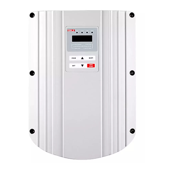
Summary of Contents for SAJ PDS23 Plus
- Page 1 PDS23 Plus Solar Pump User Manual Controller Version code : PDS23 Plus-EN-60200183-1707...
-
Page 2: Preface
PDS23 Plus Series Preface Thank you for using PDS23Plus solar pump controller. This manual provides you with relevant operation instructions and detailed description of parameters. Please read this manual carefully before installation, running, maintenance or inspection. Please make sure the wiring and the pump’s rotation direction is correct before use. -
Page 3: Table Of Contents
PDS23 Plus Series Content Preface ....................... - 1 - Notes for Safe Operation .................. - 4 - Chapter 1How It Works ................... - 6 - 1.1 Features........................- 7 - Chapter 2 General Information ..............- 9 - 2.1 Inspection ........................ - 9 - 2.2 Descriptions and Features .................. - Page 4 PDS23 Plus Series 5.2 Common Faults and Remedies ................- 31 - Chapter 6 Regular maintenance ..............- 33 - 6.1 Controller and Pump ....................- 33 - 6.2 Solar panels......................- 33 - 6.3 Cable ........................- 33 - Chapter 7 Backup AC power ..............
-
Page 5: Notes For Safe Operation
PDS23 Plus Series Notes for Safe Operation ■Before Installation WARNING Do not install or operate the controller that is damaged or has missing parts. Otherwise, it may result in equipment damage or harm life. ■ Installation CAUTION ◎ Hold the bottom ofthe controllerwhen installingormovingthe controller, can not justhold theshellto prevent theinjuredorbrokencontroller. - Page 6 PDS23 Plus Series ■ Operation CAUTION ◎ Do not open or remove the front cover when operation. Otherwise it may cause an electrical shock. ◎Before testing the pump must be installed; can not make the pump dry-run for a long time.In order to test the pump, the maximum dry-run time is not more than 15s...
-
Page 7: Chapter 1How It Works
Chapter 1How It Works PDS23 Plus solar pumping system serves to provide water in remote applications where electrical grid power is either unreliable or unavailable.PDS23 Plus solar pump controller can convert DC from the PV array to AC, and drive kinds of pumps. -
Page 8: Features
PDS23 Plus Series D. Pump and Motor E. Water Source Level Switches (optional) F. Tank Level Switches (optional) PDS23Plus solar pump controller runs at variable speed while match the changing power provided by the solar array. Variable speed operation means there is no in-rush or surge of energy during the pump/motor start-up, helping to eliminate wear on the motor and pumping system. - Page 9 Switching to Backup AC Power The input power of the PDS23 Plus solar pump controller can be switched to standby AC power through a power switch box. Note: the controllers support power input 380VAC three-phase.
-
Page 10: Chapter 2 General Information
PDS23 Plus Series Chapter 2 General Information PDS23Plus solar pump controller is a variable speed motor drive designed to run any IEC three-phase asynchronous motor. PDS23Plus solar pumping system provides water to remote locations by converting high voltage, direct current from a solar array into alternating current to run a standard three-phase asynchronous motor. -
Page 11: Protection Features
PDS23 Plus Series The controller continuously monitors system performance and incorporates a number of features for pumping system protection. In the event of a fault, the PDS23Plus solar pump controller will indicate the type of fault through the LED display mounted on the front cover of controller. -
Page 12: Pds23Plus Solar Pump Controller Model Description
PDS23 Plus Series 2.4 PDS23Plus Solar Pump Controller Model Description 2.4.1 Model Description PDS23Plus2.2K ①②③④ Segment Description Options ① PDS series 2: Series of 2nd generation. ② Series ID 3: Apply to three-phase induction motor ③ Plus Enhancement type ④... - Page 13 PDS23 Plus Series 2.4.3 Input and Output Parametersof PDS23 Plus Solar Pump Controller PDS23 PDS2Plus PDS23Pl PDS23Pl PDS23Pl Controller Model Plus 2.2K us 5.5K us 7.5K us 11K Input Data PV Source Max Input Voltage(Voc) DC800V Recommended Voltage, at MPP DC500~700V...
-
Page 14: Outline &Installation Dimensions
PDS23 Plus Series 2.5 Outline &Installation Dimensions 2.5.1 Outline &installation dimensions diagram (Unit: mm) 144.3 155.6 Figure 2 PDS23 Plus 2.2K,PDS23 Plus 4K Outline &installation dimensions diagram Figure 3PDS23 Plus 5.5K,PDS23 Plus 7.5K,PDS23 Plus 11K Outline &installation dimensions diagram - 13 -... -
Page 15: Chapter 3Mechanical And Electrical Installation
60℃, but in order to avoid failure caused by overheating, it is recommended to install the controller in shadow position. PDS23 Plus solar pump controller can be installed outdoors, but to avoid direct sunlight; it can be installed in the bracket under the solar module. -
Page 16: Electrical Installation
PDS23 Plus Series 3.2 Electrical Installation 3.2.1 Terminals The following are typical figures of terminal blocks. U V W DC/AC INPUT PUMP To reverse direction, The DC and AC can't reverse any two input at the same wires. time. Figure 5 Main terminals (The sequence may be different from actual product) - Page 17 PDS23 Plus Series WARNING Before connect DC wiring, following the steps below to prevent hazardous electric shock resulting in serious injury or device burning. • Make sure that the external DC disconnect switch is off. •Make sure that AC power is disconnected (If AC power supply is wired as backup power,AC and DC power supply can not simultaneously put into the controller, otherwise it will damage the controller.)
- Page 18 PDS23 Plus Series It is recommended that use a wire tube to protect the electric wire from the destruction of wildlife and natural weathering, and bury the wire tube into the ground to strengthen protection. If you do not use a wire tube, you can use a higher quality outdoor cable.
- Page 19 PDS23 Plus Series Floating ball switch request: 1. Three signal line 2. The minimum requirements for 1 mm² line diameter, the distance up to 600m 3. I f the application is in a long distance transmission, the need to use the shielded wire.The end of the shielding layer close to the controller needs to be grounded, the...
- Page 20 PDS23 Plus Series 3.2.9 System Wiring Diagram Pump DC/AC INPUT To reverse direction, The DC and AC reverse any two can't input at the wires same time Remote Float Low-water Switch sensor probe COM M4 M5 M6 COM U V W...
-
Page 21: Chapter 4 Start-Up And Operation
PDS23 Plus Series Chapter 4 Start-up and Operation 4.1 Keypad Description ALM1 ALM2 STOP 5 0 .0 0 Digital Display Up increase Program/exit Shift key PRGM SHIFT Data enter Run/stop ▼ STOP Down decrease Figure 10 Keypad Schematic Diagram 4.1.1 Key Functions... -
Page 22: Keypad Operation Process
PDS23 Plus Series 4.1.2Indicator Light Instruction RUN: (Always on)running instruction;(Flicker)sleep instruction STOP: stop or standby instruction ALM1: controller fault alarm ALM2: water shortage or full of water alarm 4.2 Keypad Operation Process 4.2.1 Parameter Setting : Three levels of menu are as following •... -
Page 23: Trial Operation
PDS23 Plus Series 4.2.2 Fault Reset After the controller has failed, the controller will display the relevant fault code information. The conventional fault code (E002/3/4/5/6/7/8/9/10/11/12/18) can automatically reset after 10s operation, and can also choose to reset the RUN/STOP on the keyboard. If the conventional failure persists, the controller will reset once every 10s. -
Page 24: Running Status Panel Display Parameters
PDS23 Plus Series If the pump is in dry-run, the maximum operating time can not exceed 15seconds; otherwise it may cause damage to the pump. If the pump steering error, close the DC switch, according to the pump / motor wiring to change the wiring of the motor section of the two leads. - Page 25 PDS23 Plus Series Function Modifica Function Descriptions Unit Factory Setting Code tion Type Group: Basic Parameters High limit of 〇 ~ F0.12 30.00 60.00 50.00 running frequency Low limit of ~ F0.14 0.00 F0.12 20.00 running frequency 〇 ~ F0.18...
- Page 26 PDS23 Plus Series Function Modifica Function Descriptions Unit Factory Setting Code tion Type Inverter firmware ◎ F7.10 version Accumulative ◎ ~ F7.11 9999 hour running time FA Group: Protection and Malfunction Parameters 0: No fault 1: Inverter module protection (E001) Fault record of the ◎...
- Page 27 PDS23 Plus Series Function Modifica Function Descriptions Unit Factory Setting Code tion Type Output current ◎ FA.18 when fault occurs DC bus voltage ◎ FA.19 when fault occurs FD Group: Solar pumping special parameters 10:Disable Auto start when 〇 FD.07 power on 11:Enable...
- Page 28 PDS23 Plus Series FD.07, Automatic start when power on: the factory defaults to 10 (disabled).Itcan be set to 11 (enabled), then as long as the solar module power supply, the controller will automatically start and achieve automatic operation of the whole day.
-
Page 29: Chapter 5 Diagnostics And Troubleshooting
PD20Series Chapter 5 Diagnostics and Troubleshooting The PDS23Plus solar pump controller will attempt to drive the pump to deliver water even under adverse conditions. To ensure years of reliable service, it must also protect the system components from conditions that might result in equipment damage. - Page 30 PD20Series Fault code Fault description Possible causes Remedy Too-fast deceleration Increase deceleration time Over-current Too-heavy and large-inertia Add proper braking units E003 during load deceleration Replace with higher-rating lower-rating controller controller Sudden change of load Check the load Over-current at Check the input power Too low input voltage E004...
- Page 31 PD20Series Fault code Fault description Possible causes Remedy Check input power supply Too-low input voltage or wiring E011 Motor overload Replace with higher-rating Lower-rating controller controller Broken wires in the output cable Check the wiring and E013 Output phase loss Broken wires in the motor installation winding...
-
Page 32: Common Faults And Remedies
PD20Series Fault code Fault description Possible causes Remedy Dry well or slow water Wait for water to recover E020 Well Level Fault recovery or reinstall the pump Wait until water level comes below the low level Tank Level Fault E021 High level limit is reached. - Page 33 PD20Series ① If there is no enough sun light, and the controller's input power is not enough. ② Motor wiring errors cause the pump to reverse, change the wiring. ③ The motor shaft vibratesand can not rotate, it may be caused by the wiring errors;Need to re check the motor wiring.
-
Page 34: Chapter 6 Regular Maintenance
PD20Series Chapter 6 Regular maintenance Controller and Pump • Controller Periodically checking of Status display, error code display and fault record, long term verification of cooling fan and cleaning of heat sink are needed. • pump The pump’s motor is permanently sealed, no need to maintain. Pump head is a mechanical device, may be used for a period of time, due to the sand in the water, and other impurities cause a certain wear, the performance of the pump needs to be regularly detected. -
Page 35: Chapter 7 Backup Ac Power
PD20Series Chapter 7 Backup AC power In order to ensure continuous water supply, solar water pump system can be manually switched to standby AC power supply when the light is insufficient or wet days. When switching, the need to ensure that the DC and AC power supply reliable mutual lock. - Page 36 PD20Series System Report System and Components Date ofPurchase Distributor (Contact details) System Controller Serial Number Motor Serial Numberor Power Pump Type Submersible Surface Solar Power Solar Module Manufacturers Type PeakVoltage(V mp) Open Circuit Voltage(Voc) Quantity Connection Series Parallel - 35 -...
- Page 37 PD20Series Installation Installation Date Installer (contact details) Submersible Pump Surface Pump Well Depth m/ft Head m/ft (self suction) Pump Depth m/ft Suction lift m/ft Vertical Height (well m/ft mouth to the tower top) MAX. Suction m/ft lift Static Water Level m/ft Dynamic Water Level m/ft...
- Page 38 PD20Series V1.1 Inverter - 37 -...
Need help?
Do you have a question about the PDS23 Plus and is the answer not in the manual?
Questions and answers