Table of Contents
Advertisement
Quick Links
AIR CONDITIONER
Refer to the service manual in the GSPN (see the rear cover) for the More information
SPLIT-TYPE AIR CONDITIONER
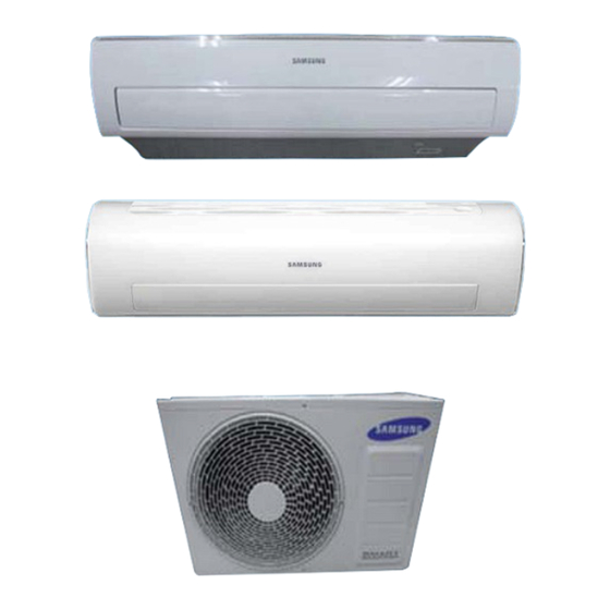
INDOOR
MODEL CODE AR09HSFNBWKNET AR09HSFNBWKXET
AR12HSFNBWKNET AR12HSFNBWKXET
AR09HSFSBWKNZE AR09HSFSBWKXZE
AR09HSFNBWKNZE AR09HSFNBWKXZE
AR12HSFSAWKNZE AR12HSFSAWKXZE
AR12HSFNBWKNZE AR12HSFNBWKXZE
AR12HSFSRWKNER AR12HSFSRWKXER
AR12HSFNRWKNER AR12HSFNRWKXER
AR09HSSDRWKNER AR09HSSDRWKXER
AR09HSFSBWKNET AR09HSFSBWKXET
BASIC CODE AR12HSFSAWKNET AR12HSFSAWKXET
CONTENTS
1
P .
e r
a c
t u
o i
s n
2. Product Specifications
3. Alignment and Adjustments
4. Disassembly and Reassembly
5. Disassembly WIFI
6. Electrical Parts List
7. Wiring Diagram
8. PCB Diagram
9. Operating Instructions
10. Troubleshooting
11. Block Diagram
12. Reference Sheet
OUTDOOR
Advertisement
Table of Contents


Need help?
Do you have a question about the AR09HSFNBWKNET and is the answer not in the manual?
Questions and answers