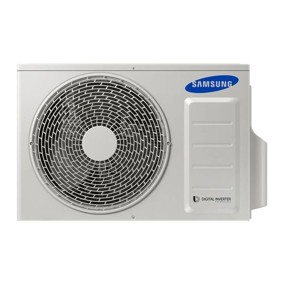
Samsung AR12HSSDBWKNEU Service Manual
Hide thumbs Also See for AR12HSSDBWKNEU:
Table of Contents

Advertisement

AR09HSSFAWKNEU
AR12HSSFAWKNEU
AR09HSSFBWKNEU
AR12HSSFBWKNEU
AR12HSSFMWKNAX
AR09HSSFAWKXEU
AR12HSSFAWKXEU
AR09HSSFBWKXEU
AR12HSSFBWKXEU
AR12HSSFMWKXAX
Basic model:
AR12HSSDBWKNEU
Model:
AR09HSSFAWK
AR12HSSFAWK
AR09HSSFBWK
AR12HSSFBWK
AR12HSSFMWK
AR09HSSFAWKNEU
AR12HSSFAWKNEU
AR09HSSFBWKNEU
AR12HSSFBWKNEU
AR12HSSFMWKNAX
AR12HSSDBWKXEU
AR09HSSFAWK
AR12HSSFAWK
AR09HSSFBWK
AR12HSSFBWK
AR12HSSFMWK
AR09HSSFAWKXEU
AR12HSSFAWKXEU
AR09HSSFBWKXEU
AR12HSSFBWKXEU
AR12HSSFMWKXAX

Advertisement

Table of Contents
loading

Summary of Contents for Samsung AR12HSSDBWKNEU

  • Page 1 AR12HSSDBWKXEU Basic model: AR12HSSDBWKNEU Model: AR09HSSFAWK AR09HSSFAWK AR12HSSFAWK AR12HSSFAWK AR09HSSFBWK AR09HSSFBWK AR12HSSFBWK AR12HSSFBWK AR12HSSFMWK AR12HSSFMWK AR09HSSFAWKNEU AR09HSSFAWKXEU AR12HSSFAWKNEU AR12HSSFAWKXEU AR09HSSFBWKNEU AR09HSSFBWKXEU AR12HSSFBWKNEU AR12HSSFBWKXEU AR12HSSFMWKNAX AR12HSSFMWKXAX AR09HSSFAWKNEU AR12HSSFAWKNEU AR09HSSFBWKNEU AR12HSSFBWKNEU AR12HSSFMWKNAX AR09HSSFAWKXEU AR12HSSFAWKXEU AR09HSSFBWKXEU AR12HSSFBWKXEU AR12HSSFMWKXAX...
  • Page 2: Table Of Contents

    6. Electrical Parts List ························································································ 6-1 6-1 INDOOR MAIN PCB (DB92-02873E) ············································· ···························································· 6-2 INDOOR SUB PBA(DB92-02874A) ················································································································· 6-3 OUTDOOR MAIN PBA(DB92-02866A)-09K··················································· · ············································· 7. Wiring Diagram ······························································································ 7-1 7-1 Indoor Unit····························································································································································· 7-2 Outdoor Unit ························································································································································ 7-3 ASSY WIFI KIT ························································································································································ Samsung Electronics...
  • Page 3 12-1 Low Refrigerant Pressure Distribution ····································································································· 12-1 12-2 Pressure & Capacity mark ······························································································································ 12-1 12-3 Q & A for Non-trouble····································································································································· 12-2 12-4 Cleaning /Filter Change ································································································································· 12-5 12-5 Installation ··························································································································································· 12-6 12-6 Installation Diagram of Indoor Unit and Outdoor Unit ···································································· 12-7 Samsung Electronics...
  • Page 4: Precautions

    Do not place a cloth or other materials over it. O Remove the batteries if you don't use the remote control for a long time. (If applicable) O Use the remote control within 7 meters from the indoor unit. (If applicable) Samsung Electronics...
  • Page 5: Disposing Of The Unit

    O Young children or infirm persons should be always supervised when they use the air conditioner. O Max current is measured according to IEC standard for safety. O Current is measured according to ISO standard for energy efficiency. Samsung Electronics...
  • Page 6: Product Specifications

    Smart Installation Smart Check - Don’t worry about the trouble-shooting in your home Triple Protector Plus - Use longer without damage in unsuitable conditions Easy Installation - Secure the easy Installation of Indoor unit and pipe connection Easy Filter Samsung Electronics...
  • Page 7: Product Specifications

    2-2 Product Specifications...
  • Page 9 DB61-06187A HOLDER...
  • Page 10: Alignment And Adjustments

    Because the teat mode operate the cool mode by force not related to the set temperature / indoor temperature, check whether each subordinate is operated normally or not after completing installation Note and must turn off the power of the air conditioner. Samsung Electronics...
  • Page 11: Indoor Display Error And Check Method

    EEPROM Data Error (Main Micom Inv Micom) E474 Heatsink Sensor Error E483 Over Voltage Protection Error E484 PFC Over Load Error E485 Input Current Sensor Error E488 AC Input Voltage Sensor Error E500 Heatsink Over Temperature Error E554 Gas Leak Error Samsung Electronics...
  • Page 12: Outdoor Led Display Error And Check Method

    Outdoor LED Display Error and Check Method Samsung Electronics...
  • Page 13: Setting Option Setup Method

    1. Tack out the batteries of remote control. 2. Press the temperature button simultaneously and insert the battery again. 3. Make sure the remote control display shown as Step 2 Enter the Options Setup mode and select your options asscording to the following procedure. Samsung Electronics...
  • Page 14 When pressing the operation ON/OFF key with the direction of remote control for unit, the sound ’’Ring’’ or ’ and the OPERATION ICON( ) lamp of the display is flickering at the same time, then the input of option is completed. (If the deriving sound isn’t heard, try again pressing the ON/OFF button.) Samsung Electronics...
  • Page 15 Every time you push the button, the display panel reads . . . repeatedly. Push the Mode button to set the display panerl to 1. Every time you push the button, the display panel reads . . . repeatedly. Samsung Electronics...
  • Page 16 Model 7~12 13~18 19~24 49~54 55~60 61~66 67~72 AR09HSSFAWK/EU 012045 156A4A 271920 372937 033E3B 102432 200000 300000 AR09HSSFBWK/EU 012045 166A6B 272338 372B35 034744 10393E 200000 300000 AR12HSSFAWK/EU 012045 156A6B 272328 372A37 034645 10383E 200000 300000 AR12HSSFBWK/EU 012045 166A4A 271920 372A35 03403B 102432 200000 300000...
  • Page 17: Setting Option Setup Method

    1. Tack out the batteries of remote control. 2. Press the temperature button simultaneously and insert the battery again. 3. Make sure the remote control display shown as Step 2 Enter the Options Setup mode and select your options asscording to the following procedure. Samsung Electronics...
  • Page 18 When pressing the operation ON/OFF key with the direction of remote control for unit, the sound ’’Ding’’ or ’ and the OPERATION ICON( ) lamp of the display is flickering at the same time, then the input of option is completed. (If the deriving sound isn’t heard, try again pressing the ON/OFF button.) Samsung Electronics...
  • Page 19 Every time you push the button, the display panel reads . . . repeatedly. Push the Mode button to set the display panerl to 1. Every time you push the button, the display panel reads . . . repeatedly. Samsung Electronics 3-10...
  • Page 20 Model 7~12 13~18 19~24 49~54 55~60 61~66 67~72 AR12HSSFMWK/AX 012045 156A6B 272328 372A34 034645 10383E 200000 300000...
  • Page 21 3-12...
  • Page 22 Download connector (10pin) 3-13...
  • Page 23: Disassembly And Reassembly

    4. Disassembly and Reassembly Q Necessary Tools Item Remark +SCREW DRIVER MONKEY SPANNER - SCREW DRIVER Samsung Electronics...
  • Page 24: Indoor Unit

    Detach FILTER PRE from the PANEL FRONT. Cover Panel is assembled on bottom of indoor unit as shown in the figure. Remove the Cap Screw as shown on the right side and then remove the screw and seperate the Cover Panel. Samsung Electronics...
  • Page 25 5) Separate the hook after pushing both end of Cover Panel as shown in the figure. (Watch out for the damage of the hook) 6) Raise front part upward obliquely as shown in the figure and then remove the hooks. Samsung Electronics...
  • Page 26 Assembly of Cover Panel after service end. - Reassembly is in the reverse order of the removal. Piping and drain hose must be careful not to damage and Progress must be done with both hands. Hook (Side) Hook (Center) Screw Cap Screw Samsung Electronics...
  • Page 27 Door is assembled to the panel front two screws. Remove the two screws as shown in the figure. Take out of the cover two screws mocha-left and right in the correct direction.Get out of the door in the figure.Remove the screw and seperate hanger. Samsung Electronics...
  • Page 28 4 HOOK Structures. When separate the hook : Use the (-) screw Driver. (-)Screw Driver Insert the hook and then pull the hook as shown on the right side. (Watch out for the damage of the hook) Samsung Electronics...
  • Page 29 Parts Samsung Electronics...
  • Page 30 Parts TRAY DRAIN Before detaching TRAY-DRAIN from the main frame,you should detach assy plate-control first and seperate the connecting line. Pull the bottom of the TRAY DRAIN towards you. Samsung Electronics...
  • Page 31 Take off the CASE-CONTROL from the main frame after loosen the remaining connector. Caution: When you separate the connector, pull pressing the locking button. EVAPORATOR detach the holder pipe 2) Unfasten the screw at the left side. (use + Screw Driver) Samsung Electronics...
  • Page 32 (use + Screw Driver) To detach Evaporator from the main frame, pull the bottom of the Evaporator towards you. FAN MOTOR 1) Unfasten the screw. (use + Screw Driver) & CROSS FAN 2) Detach the FAN Motor case. Samsung Electronics 4-10...
  • Page 33 Confirm Seal of backside necessarily after replace of Assy SPI Lamp. Seal should be close adhesion to SPI Lamp. Measure as shown on the right side replace. (If the seal is not close adhesion perfectly : Defectiveness can happen) 4-11 Samsung Electronics...
  • Page 34: Outdoor Unit

    4-2 Outdoor Unit Detach the Cabinet Upper like the picture. 4-2-1...
  • Page 35 5) Loosen 2 screw(CCW) on the right side of Cabinet Front. (Use +Screw Driver) 6) Loosen 2 screw(CCW) on the left side of Cabinet Front. (Use +Screw Driver) 7) Loosen 3 screw(CCW) on the front side of Cabinet Front. (Use +Screw Driver) 4-2-2...
  • Page 37 4-2-4...
  • Page 38 1) Release Nut at Fan Boss 2) Release 3 screws st Motor Bracket. 3) Detach Motor Wire from the Assy Control Out. 4-2-5...
  • Page 39: Wifi Case

    CASE from Case-WIFI Button Separate Case-WIFI Top BUTTON from Case-WIFI Button Detach Assy Connector Wire from Case-WIFI Button WIRE *Caution When you separate the connector , pull press -ing the locking button Separate PBA WIFI from Case-WIFI Button Samsung Electronics...
  • Page 40: Assy Control In

    DB93-14217A ASSY CONNECTOR WIRE-DC GRILL MOTOR WIRE DB93-14724A ASSY CONNECTOR WIRE-DC BLDC DB93-14209A ASSY CONNECTOR WIRE-DC DISPLAY MOTOR DB93-14723A ASSY CONNECTOR WIRE-DC STEP MOTOR DB61-05965A PLATE CONTROL-UP PLATE CONTROL-UP DB93-04695A ASSY CONNECTOR WIRE-DC DB90-07859A ASSY PLATE CONTROL RIGHT Samsung Electronics...
  • Page 41: Assy Control Out

    1 PC ASSY PCB MAIN DB92-02866A 1 PC ASSY CONNECTOR WIRE DB93-09493C 1 PC ASSY CONNECTOR WIRE DB93-09497E 1 PC ASSY CONNECTOR WIRE-POWER DB93-14275A 1 PC ASSY CONNECTOR WIRE-DC SIGNDB93-14276A 1 PC ASSY CONNECTOR WIRE-DC SIGNDB93-14277A 1 PC Samsung Electronics...
  • Page 42: Electrical Parts List

    0604-001002 PC04 PHOTO-COUPLER 0604-001002 PC05 PHOTO-COUPLER 0801-000393 IC08 IC-CMOS LOGIC 1006-001325 IC07 IC-BUS TRANSCEIVER 1202-000104 IC11 IC-VOLTAGE COMP. 1203-006245 IC03 IC-VOL. DETECTOR 1203-007526 IC02 IC-POSI.FIXED REG. 2007-000029 R850 R-CHIP 2007-000029 R851 R-CHIP 2007-000067 R713 R-CHIP 2007-000072 R717 R-CHIP Samsung Electronics...
  • Page 43 R502 R-CHIP 2007-000148 R503 R-CHIP 2007-000148 R504 R-CHIP 2007-000148 R505 R-CHIP 2007-000148 R506 R-CHIP 2007-000148 R507 R-CHIP 2007-000148 R510 R-CHIP 2007-000148 R521 R-CHIP 2007-000148 R522 R-CHIP 2007-000148 R523 R-CHIP 2007-000148 R524 R-CHIP 2007-000148 R525 R-CHIP 2007-000148 R526 R-CHIP Samsung Electronics...
  • Page 44 R410 R-CHIP 2007-001313 R811 R-CHIP 2007-001433 R618 R-CHIP 2007-007313 R401 R-CHIP 2007-007313 R402 R-CHIP 2007-007313 R403 R-CHIP 2007-009922 R301 R-CHIP 2007-009922 R302 R-CHIP 2007-009922 R303 R-CHIP 2203-000257 C705 C-CER,CHIP 2203-000257 C801 C-CER,CHIP 2203-000438 C508 C-CER,CHIP 2203-000438 C516 C-CER,CHIP Samsung Electronics...
  • Page 45 C-CER,CHIP 2203-007486 C552 C-CER,CHIP 2203-007486 C804 C-CER,CHIP 2203-007486 C808 C-CER,CHIP 2402-000120 C706 C-AL,SMD 2402-001145 C701 C-AL,SMD 2402-001145 C703 C-AL,SMD 2802-001211 X501 RESONATOR-CERAMIC DB41-01221A PCB MAIN PCB MAIN DB91-01550A IC04 ASSY MICOM 0903-001864 IC-MICROCONTROLLER DB98-31449A ASSY-LABEL MICOM ASSY-LABEL MICOM Samsung Electronics...
  • Page 46: Indoor Sub Pba(Db92-02874A)

    DB63-03547A COVER-SENSOR COVER-SENSOR DB94-04100A - ASSY PCB SMD 0406-001005 CD01 DIODE-TVS 2007-000029 J1 R-CHIP 2007-000290 R01 R-CHIP 2203-000206 C03 C-CER,CHIP 2203-000444 C02 C-CER,CHIP DB94-04099A - ASSY PCB AUTO 2401-003107 C01 C-AL 3404-001220 SW01 SWITCH-TACT DB41-01222A PCB SUB PCB SUB Samsung Electronics...
  • Page 47 POWER MODULE DB27-00097A FT001 COIL CHOKE DB61-05296A SUPPORT-IC SUPPORT-IC DB61-05916A SUPPORT-PCB SUPPORT-PCB DB68-02809A LABEL BAR CODE DB94-04084A ASSY PCB AUTO 0504-001044 Q151 TR-DIGITAL 2201-002427 C901 C-CERAMIC,DISC 2401-000303 CE162 C-AL 2401-000303 CE163 C-AL 2401-001838 CE151 C-AL 2401-002438 CE902 C-AL Samsung Electronics...
  • Page 48 Q551 TR-SMALL SIGNAL 0504-001008 Q351 TR-DIGITAL 0504-001008 Q352 TR-DIGITAL 0504-001008 Q901 TR-DIGITAL 0504-001008 Q903 TR-DIGITAL 0504-001080 Q902 TR-DIGITAL 0506-000175 IC061 TR-ARRAY 0506-000175 IC701 TR-ARRAY 0506-000175 IC702 TR-ARRAY 0601-002423 LED801 0601-002955 LED803 0601-002956 LED551 0601-002956 LED802 0604-001172 PC151 PHOTO-COUPLER Samsung Electronics...
  • Page 49 R303 R-CHIP 2007-000078 R307 R-CHIP 2007-000078 R308 R-CHIP 2007-000078 R351 R-CHIP 2007-000078 R354 R-CHIP 2007-000078 R503 R-CHIP 2007-000078 R504 R-CHIP 2007-000078 R505 R-CHIP 2007-000078 R508 R-CHIP 2007-000078 R509 R-CHIP 2007-000078 R515 R-CHIP 2007-000078 R529 R-CHIP 2007-000078 R530 R-CHIP Samsung Electronics...
  • Page 50 R304 R-CHIP 2007-000090 R305 R-CHIP 2007-000090 R528 R-CHIP 2007-000090 R532 R-CHIP 2007-000090 R533 R-CHIP 2007-000090 R551 R-CHIP 2007-000090 R552 R-CHIP 2007-000090 R553 R-CHIP 2007-000090 R554 R-CHIP 2007-000090 R555 R-CHIP 2007-000090 R559 R-CHIP 2007-000090 R565 R-CHIP 2007-000109 R531 R-CHIP Samsung Electronics...
  • Page 51 R-CHIP 2007-000614 R254 R-CHIP 2007-000614 R469 R-CHIP 2007-000614 R470 R-CHIP 2007-000614 R471 R-CHIP 2007-000614 R472 R-CHIP 2007-000614 R473 R-CHIP 2007-000614 R474 R-CHIP 2007-000651 R475 R-CHIP 2007-000683 R454 R-CHIP 2007-000683 R459 R-CHIP 2007-000683 R466 R-CHIP 2007-000763 R476 R-CHIP 6-10 Samsung Electronics...
  • Page 52 C-CER,CHIP 2203-000440 C504 C-CER,CHIP 2203-000440 C505 C-CER,CHIP 2203-000440 C506 C-CER,CHIP 2203-000440 C507 C-CER,CHIP 2203-000440 C508 C-CER,CHIP 2203-000440 C510 C-CER,CHIP 2203-000440 C512 C-CER,CHIP 2203-000440 C523 C-CER,CHIP 2203-000440 C904 C-CER,CHIP 2203-000783 C455 C-CER,CHIP 2203-000783 C458 C-CER,CHIP 2203-002002 C453 C-CER,CHIP 6-11 Samsung Electronics...
  • Page 53 C-CER,CHIP 2203-005249 C520 C-CER,CHIP 2203-005249 C521 C-CER,CHIP 2203-005249 C525 C-CER,CHIP 2203-005249 C526 C-CER,CHIP 2203-005249 C527 C-CER,CHIP 2203-005249 C701 C-CER,CHIP 2203-005249 C702 C-CER,CHIP 2203-005249 C703 C-CER,CHIP 2203-005249 C704 C-CER,CHIP 2203-005249 C903 C-CER,CHIP 2203-006158 C201 C-CER,CHIP 2203-006158 C203 C-CER,CHIP 6-12 Samsung Electronics...
  • Page 54 CE401 C-AL,SMD 2402-001368 CE402 C-AL,SMD 2402-001368 CE403 C-AL,SMD 2802-001165 X201 RESONATOR-CERAMIC 2802-001211 X501 RESONATOR-CERAMIC DB41-01227A PCB MAIN PCB MAIN DB91-01517A IC501 ASSY MICOM 0903-001843 IC-MICROCONTROLLER ASSY-LABEL DB98-31449A ASSY-LABEL MICOM MICOM DB91-01534A IC201 ASSY MICOM DB09-00596A IC MICOM 6-13 Samsung Electronics...
  • Page 55: Wiring Diagram

    7. Wiring Diagram 7-1 Indoor Unit DB68-04014A-4 Samsung Electronics...
  • Page 56: Outdoor Unit

    7-2 Outdoor Unit Samsung Electronics...
  • Page 57 #2 : N.C #1 : DC 5V #1 : DC 310V~340V #9 : GND #2 : GND #2,#3 : N.C #10 : DC 12V #3 : DC 12V #4 : DC 19V~27V #5 : AGND CN31 - DOWNLOAD DOWNLOAD Samsung Electronics...
  • Page 58: Outdoor Pcb

    #1 :REACTOR1 #1,#3 :AC220~240V #1 :N #2:N.C #2 :REACTOR2 #3:AGND #4:DC15V #5:FANRPM #6:FANFEEDBACK CN002 - POWER-L CN003 - EARTH CN150 - SMPS AC CN402 - COMP #1 :W #1 :L #1 :EARTH #1,#3 :AC220~240V #2 :V #3 :U Samsung Electronics...
  • Page 59: Wire Connecting The Indoor Unit Terminal Blocks

    If not, there exists a possibility of fire which can be caused by electric heat in the connecting part. : Good Bad : Ring terminal is connected reversely Bad : Not clamped Screw Bad : In the gap between Ring terminal & Screw Bad : Unused Ring Terminal Samsung Electronics...
  • Page 60: Operating Instructions

    Wi-Fi module Air intake Virus Doctor Lamp Virus Doctor Vertical air Horizontal air Display Temperature indicator / Filter Reset indicator Defrost indicator Power consumption indicator / Auto clean indicator Power button/ W i-Fi indicator Remote controller receiver Timer/Auto cleanindicator Samsung Electronics...
  • Page 61: Wireless Remote Control-Buttons And Display

    Filter Reset Reset the Filter Clean reminder Usage Display the amount of power consumption for few seconds on Time set the indoor unit display: Set the current time To silence the beep sound when pressing the button. Samsung Electronics...
  • Page 62 Incase you wish to cancel the options or settings that you havejustset, press the Options or Settings button again,then the most recently selected item will blink and you may simply cancel it by pressing the SET button while selected item is blinking. Samsung Electronics...
  • Page 63: Troubleshooting

    HEAT mode, and indoor fan and out- Indoor fan and outdoor fan stop operation door fan do not operate intermittently for within 20% intermittently in a HEAT mode. of the total heater operation. Samsung Electronics 10-1...
  • Page 64: Communication Error

    Is the power is normal? Exchange the PBA of no power unit (check the LED Lamp) Exchange the indoor unit PBA. Is the communication error occurred again? Terminate the service. Exchange the outdoor unit PBA. 10-2 Samsung Electronics...
  • Page 65 Is the connection of power cable supply power and measure the voltage of #1-#2 in and communication cable normal? the connector Exchange the indoor PBA Below 0.5V or Over 4.5V? Micom error or connector check Exchange the indoor PBA Samsung Electronics 10-3...
  • Page 66 Is the connection of power cable supply power and measure the voltage of #3-#4 and communication cable normal? and #5-#6 in the connector Exchange the indoor PBA Below 0.5V or Over 4.5V? Micom error or connector check Exchange the indoor PBA 10-4 Samsung Electronics...
  • Page 67 Is the connected louver wire? Does operation start when swing button of the Normal remote control unit pushed? Is the voltage changeable at the pin#2~#5 of CN61, Exchange the PBA CN62, CN63 (louver connector)? Up/Down louver motor is faulty. Samsung Electronics 10-5...
  • Page 68 Is the voltage of CN72 Exchange the Indoor PBA #3-#5 and #3-#6 with in 1Vdc~15Vdc during the operation? PBA problem or Motor problem Change the PBA first and check the operation Exchange the Fan motor 10-6 Samsung Electronics...
  • Page 69: Outdoor Temperature Sensor Error

    Is the connection of power cable supply power and measure the voltage of "B"in the connector and communication cable normal? Exchange the Outdoor PBA Below 0.5Vdc or Over 4.5Vdc? Micom error or connector check Exchange the Outdoor PBA Samsung Electronics 10-7...
  • Page 70 Is the connection of power cable supply power and measure the voltage of "B"in the and communication cable normal? connector Exchange the Outdoor PBA Below 0.5Vdc or Over 4.5Vdc? Micom error or connector check Exchange the Outdoor PBA 10-8 Samsung Electronics...
  • Page 71 Is the connection of power cable supply power and measure the voltage of "B"in the and communication cable normal? connector Exchange the Outdoor PBA Below 0.5Vdc or Over 4.5Vdc? Micom error or connector check Exchange the Outdoor PBA Samsung Electronics 10-9...
  • Page 72 Restart after power off Is the discharge over temperature Terminate the service sensor error appeared again? Download the EEPROM data Is the discharge over temperature Terminate the service sensor error appeared again? Exchange the Outdoor PBA Exchanged the Compressor 10-10 Samsung Electronics...
  • Page 73 Is the voltage of "A" #3-#5 and Exchange the Outdoor PBA #3-#6 with in 1Vdc~15Vdc during the operation? PBA problem or Motor problem Change the PBA first and check the operation Exchange the Fan motor Samsung Electronics 10-11...
  • Page 74: Compressor Starting Error

    Is the connection of compressor wire is normal? Connect the comp wire normally Download the EEPROM data Is the restart error occurred again? Terminate the service Is the compressor body and interphase Exchange the Outdoor PBA resistance insulated? Exchange the compressor 10-12 Samsung Electronics...
  • Page 75 Is the connection of compressor wire is normal? Connect the comp wire normally (PBA and Compressor) Is the restart error occurred again? Terminate the service Is the compressor body and Exchange the Outdoor PBA interphase resistance insulated? Exchange the compressor Samsung Electronics 10-13...
  • Page 76 Connect the comp wire normally Is the O.C error occurred again? Terminate the service Is the condition of indoor/outdoor temperature Restart after returning to the normal load normal load? Is the O.C error Terminate the service occurred again? 10-14 Samsung Electronics...
  • Page 77 Is the position of Correct the sensor position or temperature sensor and sensing exchange the sensor value normal? Is the compressor body and interphase resistance Exchange the Outdoor PBA insulated? Exchange the compressor Samsung Electronics 10-15...
  • Page 78 ("A") is normal in operation mode? Normal range(280Vdc~320Vdc) Is the DC_link Exchange the Outdoor PBA sensing voltage("B") is normal in operation mode? Normal range (0.2Vdc~4.8Vdc) Exchange the Outdoor PBA Is the reactor insulation damaged? Exchange the Reactor 10-16 Samsung Electronics...
  • Page 79 Start the operation (cooling mode or heating mode) Is the DC_link sensing voltage("B") is normal in operation mode? Exchange the Outdoor PBA Normal range (0.2Vdc~4.8Vdc) Is the reactor insulation damaged? Exchange the Outdoor PBA Exchange the Reactor Samsung Electronics 10-17...
  • Page 80 Check the input power in the powercord. Normal range(180Vac ~ 270Vac) Restart after power off. Start the operation (cooling mode or heating mode) Is the DC_link voltage ("A") is normal in operation mode? Check the input power Normal range(280Vdc~320Vdc) 10-18 Samsung Electronics...
  • Page 81 Is the DC_link sensing Exchange the Outdoor PBA voltage("D")is normal in operation mode? Normal range (0.2Vdc~4.0Vdc) Is the reactor insulation damaged? Exchange the Outdoor PBA Exchange the Reactor Samsung Electronics 10-19...
  • Page 82 Is the position of Correct the sensor position or temperature sensor and the sensing exchange the sensor value normal? Is the connection cable for the compressor and power Correct the cable connection terminal normal? Exchange the Outdoor PBA 10-20 Samsung Electronics...
  • Page 83 IC451 AR12HSSFMWKNAX R426,R425 R410,R411,R412 IC451 Restart after power off. Is the PFC shunt and IPM Exchange the Outdoor PBA shunt resistance value correct? Is the current sensor error appeared again? Terminate the service Exchange the Outdoor PBA Samsung Electronics 10-21...
  • Page 84 4) Is the cover assembly in control-box normal? 2. Troubleshooting procedure Restart after power off. Are there screws in PBA-heatsink? Fastening the screw (4 screws) Check the fan connection Is the fan operation normal? Change the Fan motor Exchange the Outdoor PBA 10-22 Samsung Electronics...
  • Page 85 Is the Comp Vlimit error occurred again? Terminate the service Is the condition of indoor/outdoor temperature Restart after returning to the normal load normal load? Is the O.C error Terminate the occurred again? service Samsung Electronics 10-23...
  • Page 86 Is the position of Correct the sensor position or temperature sensor and sensing exchange the sensor value normal? Is the compressor body and interphase resistance Exchange the Outdoor PBA insulated? Exchange the compressor 10-24 Samsung Electronics...
  • Page 87 2. Troubleshooting procedure MODEL "A" power off and download EEPROM data AR09(12)HSSFAWKNEU CN251 (or. Insert the service EEPROM IC) AR09(12)HSSFBWKNEU CN251 AR12HSSFMWKNAX CN251 Restart after power off Terminate the service Is the error appeared again? Exchange the Outdoor PBA Samsung Electronics 10-25...
  • Page 88 * Heating mode * * Cooling mode * Is the outdoor temperature over 40 or Is the outdoor temperature under -7 under -30 ? The temperature condition is too poor to operate. Wait until temperature is changed 10-26 Samsung Electronics...
  • Page 89 Terminate the service. Check the EEV valve operation. Is the EEV valve connection normal? Connect the EEV valve. Is the EEV valve is operation? Check the sound of EEV valve Change the EEV valve. after power on. Samsung Electronics 10-27...
  • Page 90 Check the pipe crack. Is the pressure of refrigerant normal? Fill up the refrigerant. Exchange the Indoor PBA Exchange the Outdoor PBA 10-28 Samsung Electronics...
  • Page 91 Check the fuse open or not? (F001) Exchange the Main PBA Restart after power off. Is the power normal? Check the power source. Is AC power is normal for SMPS? Exchange the Main PBA CN150 : 220Vac~240Vac Check SMPS wire connection Samsung Electronics 10-29...
  • Page 92 DC wire (3PIN RED, 3PIN BLU) with Main PBA Connector CN151, CN152, Check the DC voltage in Exchange the Main PBA Main PBA. Is the voltage is normal in Main PBA? (Main : CN151,CN152 Check) Exchange the Main PBA, SMPS PBA 10-30 Samsung Electronics...
  • Page 93 Exchange the PBA "F":270Vdc~320Vdc Is the SMPS is normal? Exchange the PBA "G" Main 5V : 4.5Vdc ~ 5.5Vdc Is the SMPS is normal? Exchange the PBA "H" Main 12V : 11Vdc ~ 13Vdc Exchange the PBA Samsung Electronics 10-31...
  • Page 94 1) Check the power condition at customer's house (Is there any power noise?) 2) Have been there power failure? 2. Troubleshooting procedure MODEL "A" AR09(12)HSSFAWKNEU AR09(12)HSSFBWKNEU AR12HSSFMWKNAX Restart after power off Is the AC line zero cross signal error appeared again? Terminate the service Exchange the Outdoor PBA 10-32 Samsung Electronics...
  • Page 95 Reset the option code again at indoor unit Is the capacity miss match error appeared again? Terminate the service Download the EEPROM data Is the capacity miss match error appeared again? Terminate the service Exchange the Outdoor PBA Exchange the Indoor PBA Samsung Electronics 10-33...
  • Page 96 2) Check the battery in remote control 3) All the lights out and check again : Change electronic typed to a fluorescent light 4) Put the set in operation and check the voltage of display PBA 5) Replace the display PBA 10-34 Samsung Electronics...
  • Page 97 Is the EEV valve is operation? Change the EEV valve. Check the sound of EEV valve after power on. Check the pipe crack. Is the pressure of refrigerant normal? Fill up the refrigerant. Exchange the Indoor PBA Exchange the Outdoor PBA Samsung Electronics 10-35...
  • Page 98 - Discharge temperature and the indoor [Execute the troubleshooting] temperature measurements confirm Check the refrigerant leaks. that the difference is more than 10 . Check the PCB Relay. - Fill up perfectly refrigerant after re-vacuum. Execute the related trouble- shooting. 10-36 Samsung Electronics...
  • Page 99: Pcb Inspection Method

    2) The fan motor of the indoor unit . Fan motor connector(CN72) is faulty. 1. Fan speed(high) doesn't run. 2. Continuous Operation 3) The power voltage between terminal #1-#3 of the . PBA is faulty. connector(CN72) is 0V. Samsung Electronics 10-37...
  • Page 100 (There is no problem with Main PBA in this case) - In the above case, the change of all-in-one Terminal Block will make Main PBA operate again. Circuit Block 3. Measurement method of fair/defective thermal fuse Fail Defective 10-38 Samsung Electronics...
  • Page 101: Block Diagram

    · BUZZER DRIVE ON,OFF TIMER · STEPPING MOTOR SELECT(UP/DOWN) - BLDAE CONTROL(H/V) TEMP/HUMI SELECT DC12V DC5V BEEP ON/OFF SELECT DISPLAY ON/OFF SELECT SMPS POWER BLOCK WPS MODE SELECT DC5V AP MODE SELECT DC12V DC15V AC230V AC INPUT Samsung Electronics 11-1...
  • Page 102: Outdoor Unit

    11-2 Outdoor unit 11-2 Samsung Electronics...
  • Page 103 2) The fan motor of the indoor unit . Fan motor connector(CN72) is 1. Fan speed(high) doesn't run faulty 2. Continuous Operation 3) The power voltage between terminal #3-#5 of the . PBA is faulty connector(CN72) is 0V Samsung Electronics 11-3...
  • Page 104 1) Normal : RED on, GRN blink, YEL off 2) Abnormal . L,N,C wire wrong wiring Check the LED lamp display - All off : check no power . Outdoor PBA is faulty - abnormal display : check error mode 11-4 Samsung Electronics...
  • Page 105: Reference Sheet

    0.001341 0.10197 0.73756 4.1868 14.286 0.0056146 0.42693 3.088 1.163 0.27778 3.9683 0.0015596 0.11859 0.85778 0.29307 0.06999 0.252 3.9302x10 0.029885 0.21616 745.7 178.11 641.19 2,544.4 76.04 9.8067 2.3423 8.4322 33.462 0.013151 7.233 1.3558 0.32383 1.0658 4.6262 0.0018182 0.13826 Samsung Electronics 12-1...
  • Page 106: Q & A For Non-Trouble

    It occurs when the drain pump is plugged out or it is out of order. Check the power of the drain pump and the position of the drain hose, and when the pump is faulty, contact the drain pump manufacturer. Samsung Electronics do not manufacture drain pumps. So, we are not able to correct the drain pump problems.
  • Page 107 Also, the remote con- troller may mot work under intensive light from a 3-wave length lamp or a neon sign due to the EMI. In this case, take the remote controller closer to the receiver. Samsung Electronics 12-3...
  • Page 108 There is a cost table. But, our service engineer needs to visit to total up the cost correctly. When you move in, make sure to contact Samsung Electronics Service Center or Authorized Service Agent in advance to streamline the process.
  • Page 109: Cleaning /Filter Change

    Clean the Air filter with a vacuum cleaner or soft brush. If dust is too heavy , rinse it with running water. Insert the air filter back in its original Dry the Air filter in a ventilated area. position it once a week. Samsung Electronics 12-5...
  • Page 110: Installation

    Electric and earth work shall meet the "Electric Facility Technology Standard" and the "Internal Wire Regulation" of the Electric Business Laws. ■ Inspection & Trial Run Upon completion of the tests, you shall make a trial run while you explain the main functions of the air conditioner to finish the installation. 12-6 Samsung Electronics...
  • Page 111: Installation Diagram Of Indoor Unit And Outdoor Unit

    3 way valve. And mount the service port cap to 3 way valve. Valve stem Stem cap 7) Check for gas leakage. (gas) - At this time, especially check for gas leakage from the 3 way valve's stem nuts, and from the service port cap. (liquid) Samsung Electronics 12-7...
  • Page 112 7) Close the cap of each valve. Relocation of the air conditioner entering. At this time, cover the valve of the outdoor unit and the other pipe using a cap or vinyl plug to avoid foreign material entering. 12-8 Samsung Electronics...
  • Page 113 1st 2nd 3rd 4th 5th 6th 7th 8th 9th 10th 11th 12th 13th 14th Project Capacity Sell Feature Series Color Unit Export Item Reference 3TH 4TH ITEM Item Item Export 12Year INVERTER HP Export 13Year INVERTER CO Export 14Year Export 15Year Export 16Year...
  • Page 114 North & Latin America gspn3.samsungcsportal.com China china.samsungportal.com This Service Manual is a property of Samsung Electronics Co., Ltd. © Samsung Electronics Co., Ltd. August. 2013. Any unauthorized use of Manual can be punished under applicable Code No. AC-00045K_1 International and/or domestic law.

Table of Contents