Advertisement
Quick Links
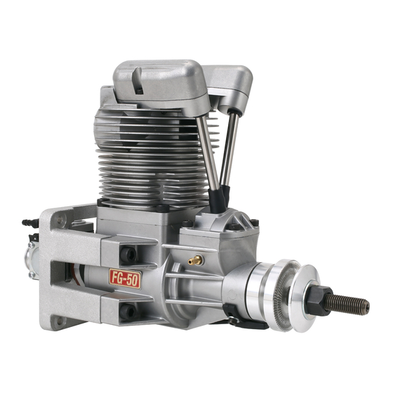
FG-50 Instruction Manual
Specifications
Bore
43.6mm
Stroke
33.6mm
Weight
Main body : 2,253g / Muffler : 62g / Ignition : 125g
(Approx.)
(including engine mount)
20"×12"〜22"×8"
CM-6
Propeller
Plug
・Spark plug[CM-6] (Attached to the engine) 1pc
Standard
・Ignition system (w/sensor)
accessories
・Choke and carburetor adjustment bar 1pc
・Filter with weight [G36-154] ・Durable tube for Gasoline (1m) [G36-155]
Optional parts
・Tappet adjusting kit [120S-161] ・Digital tachometer [G17-167]
1. Fuel
●The fuel is a mixture of regular gasoline or high-octane gasoline and high-quality 2-stroke engine oil.
●[Example of oil recommendation]
・ Klotz KL-200 Original Techniplate ・ Deluxe Materials PowerModel 2T-S ・ Castrol POWER1 RACING 2T etc.
If such oils are not available in your country, then ask the official SAITO distributor in your country for an high-quality synthetic oil specifically formulated
for 2-stroke engine fuel mixtures.
●Be sure to use the mixture "gasoline : oil =15~20 : 1" by volume ratio. (Ex. 1000ml of gasoline should be mixed with more than 50ml of oil ).
●During the break-in process, use 15:1 mixed fuel to ensure the best lubrication for initial running.
●Any damage caused by the fuel used, in which the oil ratio is lower than 20:1 will not be covered by warranty.
●Do not use gasoline containing ethanol. It may cause not only power loss but also corrosion inside the engine.
Equipped with fuel tank
Vent line
Fuel filler line
Firewall
fuel supply to carburetor
Gasoline-compatible tubing
Center of engine
Close as possible
2. Ignition
●Ignition arrangement- Place the main unit as
far from other electrical devices as possible.
(1) Plug cord (meshed high tension cord)
Insert the plug cap of the plug cord deeply into the plug
attached to the cylinder to make sure it will not come off.
(2) Sensor cord
Connect with the cord from the sensor attached to the
engine.
(3) Battery cord (black / red cord)
Use a fully charged battery that has adequate spec. (6-12V,
more than 1000mA is recommended). Between the battery
and main unit, make sure to set a heavy duty switch whose
capacity is higher than 3A.
(4)Tachometer cord
Connect the digital tachometer (Option). Otherwise the
connector is normally vacant.
3. Propeller
●Recommended propellers are Falcon 21"x10"〜22"x8" (carbon propeller) .
●Choose a reliable propeller that brings maximum rotation speed of 6,000 to 7,000 rpm on the ground. The propeller must match the airplane.
●Use a well-balanced one. Never use the propeller that has been scratched or damaged even if slightly.
●Do not use propellers that are either too small or too large in load, as this can lead to engine failure.
●After use, regularly check for any looseness in the propeller nut and tighten if it is loose. Pay special attention to wooden propellers as they are prone to
compression.
Disp.
50. 2cc
Applications
1,800 - 7,000rpm
RPM Range
Max on ground
(Approx.)
(Approx.)
6 -12V, greater than1,000mA (2-3S Lipo or LiFe)
Battery for ignition system
*Recommend 2S Lipo 20~25C
・Muffler
1pc
・Tappet adjustment tool
Hexagonal wrench (2.0mm) for Tappet adjustment
1set
・Plug wrench
1pc
spanner for Tappet adjustment
Limit gauge (0.1t) for Tappet adjustment
Vent line details
Gasoline-compatible
tank stopper
Fuel Tank
Fuel Level
Center of fuel tank
Filter with weight
To Outside of the plane
Ignition configuration
Plug cap
(1)Plug cord
Main unit
(4)Tachometer cord
(Brown/Red/Orange)
(2)Sensor cord
(Black)
Sensor
4. Method of choke
ver. July, 2024
(No need when you use starter)
※Choking is the means by which fuel is fed to the engine when you start it by hand flipping.
Thus it is unnecessary when using starter. Starting with a electric starter is recommended for safety.
●In advance, make a thin hole in the cowling to insert the choke bar / slow needle adjustment bar.
●During choking, be sure to turn off the ignition switch.
Acrobatics -2st 30㏄ class
●As shown in the fig, pass the choke bar (with M3.5 thread on its tip) through the hole in the
Scale -2st 30~50cc class
cowling. Then turn the bar to insert into the M3.5 internal thread at the center of the throttle lever.
6,000 - 7,000 rpm
●Fully close the throttle and pull the choke bar and fix it with a clip or clamp as shown in the fig
so that it may not go back to the previous position.
●Grasp the prop by hand and turn it several times in the direction of normal operation (CCW)
until the carburetor generates hissing-like sound. After hearing this sound for about 5 times,
quickly flip the prop approximately 10 times.
1set
●Remove the choke bar. Then power on the ignition system and flip the prop quickly to start
the engine. If the engine doesnʼt start, repeat the choking procedure.
5. Break-in
●Prop-recommendation : 21"x10"〜22"x8" carbon
●Use 15:1 fuel:oil ratio for break-in.
●Never make the fuel mixture lean during Break-in. It could cause seizure even during idling
or low speed running.
●Before starting the engine, open the main needle Approx. 3 turns and the slow needle
Approx. 5 turns CCW each from fully close.
●Start the engine (using a starter is recommended for safety).
●Soon after starting, Open throttle gradually up to full open, in the meantime turn the main
needle CCW. Continue to turn the main needle CCW until the RPM declines (to approx
4,000rpm), keeping the throttle fully opened.
●If RPM doesnʼt drop, turn the slow needle CCW to make mixture much richer.
●Run in this very rich condition for 1 liter of fuel.
●Now "initial" break-in is done.
6. Adjustment of carburetor after initial break-in.
●Peak adjustment
◇After the initial break-in, keeping the main needle unchanged, open the slow needle Approx. 5 turns CCW from fully closed (Then throttle should be fully closed).
Vent line
◇Start the engine (using a starter is recommended for safety).
◇Achieve the peak at full throttle. →Turn the main needle CW gradually to the position where the RPM is greatest (the peak). Turning over the needle CW
past the peak could lead to seizure so turn it slowly and carefully. Once the peak is passed, the RPM will drop suddenly. In that case immediately return
(CCW) the main needle.
◇Once achieving peak RPM, return the throttle to low speed. Adjust the slow needle following next chapter.
●Slow needle Adjustment *Please be careful not to press the slow needle too forcefully during adjustments, as this may cause the engine to stop.
◇After achieving peak, open the throttle from idle to full open quickly several times to check responce.
◇If the engine hesitates for a moment or stalls before the engine reaches max RPM, the mixture is too lean. Then turn the slow needle CCW slightly.
◇If the engine is slow to reach max RPM, the mixture is too rich. Then turn the slow needle CW slightly.
◇Adjust the slow needle in above way until RPM follows the throttle movement smoothly. The important point is to adjust the slow needle in the condition
where the main needle has been adjusted to its peak.
◇After the slow needle is adjusted, stop the engine and make a note of the main needle position at the peak. (So that you can refer to how many turns CCW
from fully closed position when you lost right position.)
●Pre-flight / Flight adjustment
Switch (not included)
◇Before flight open the main needle CCW more than a half turn from the peak position. (At least open the main needle 3 turns CCW from the position
Capacity : 3A〜
fully closed.) This is to make the fuel mixture richer in the air where the RPM get higher than on the ground.
◇After all adjustments are made, fly your aircraft and fine tune the engine according to the situation. Basically tuning should be done with the main needle.
The slow needle also requires fine tune when there is a large temperature difference, such as in summer and winter.
◇The break-in process and needle adjustment are done now. Proceed with the tappet adjustment using the following steps.
◇The best tune depends on various factors such as propeller, temperature, humidity, etc., so please adjust the needles according to the situation.
(3)Battery Cord
7. Tappet adjustment
(Red/Black)
The valve clearance should be checked and adjusted after Break-in and every after 2 hours while the engine is cold. Before adjusting tappet gaps,
tighten the screws around cylinders etc.
1
Battery (not included)
Voltage : 6-12V
Capacity : 1,000mA〜
*Recommend 2S Lipo 20~25C
1. Remove the spark plug and rocker
arm covers of a cylinder. Then turn
the prop CCW by hand to place the
piston at TDC of compression stroke.
2
3
2. Loosen the lock nut and adjust
3. Once the gap is set, tighten
the gap by hexagonal wrench
the lock nut and attach the
until you get the correct gap for
plug and covers.
both of intake & exhaust.
Chalk composition
Throttle lever
Cowling
Choke bar for
insert M3.5 screw
Choke bar
Throttle valve
(Move to the left)
Slow needle
Temporary
fixed by a clip
Carburetor adjustment
Main needle
CCW
CW
to rich
to lean
Throttle lever
Slow needle
CCW
CW
to rich
to lean
*The engine is upright
4
Correct Gap
Close to "0"
with no limit
Limit gauge (0.1mm)
Must not be inserted
4. Turn the prop by hand to check if the compression is
enough. If the gap is less than 0, the valve is always
opened sightly and lose compression. Then adjust again.
Advertisement

Subscribe to Our Youtube Channel
Related Manuals for Saito FG-50


Summary of Contents for Saito FG-50
- Page 1 FG-50 Instruction Manual 4. Method of choke ver. July, 2024 (No need when you use starter) Chalk composition Throttle lever ※Choking is the means by which fuel is fed to the engine when you start it by hand flipping. Thus it is unnecessary when using starter. Starting with a electric starter is recommended for safety. Cowling Choke bar for Specifications ●In advance, make a thin hole in the cowling to insert the choke bar / slow needle adjustment bar. insert M3.5 screw Choke bar ●During choking, be sure to turn off the ignition switch. Acrobatics -2st 30㏄ class ●As shown in the fig, pass the choke bar (with M3.5 thread on its tip) through the hole in the Bore 43.6mm Stroke 33.6mm Disp. 50. 2cc Applications Scale -2st 30~50cc class Throttle valve cowling. Then turn the bar to insert into the M3.5 internal thread at the center of the throttle lever. (Move to the left) 1,800 - 7,000rpm 6,000 - 7,000 rpm RPM Range Max on ground ●Fully close the throttle and pull the choke bar and fix it with a clip or clamp as shown in the fig Weight Main body : 2,253g / Muffler : 62g / Ignition : 125g (Approx.) (Approx.) (Approx.)...
- Page 2 Note: FG-50 Parts List ●Because it uses oil mixed gasoline, the aircraft may become dirty due to exhaust smoke. Firewall Cuttting dimension ●Use a reliable and well-balanced prop. Otherwise it may cause an abnormal vibration and could result in a serious accident. PART NAME PART NAME <View from rear> ●During operation, all engine screws can loosen due to metal heat expansion. Check and tighten occasionally. 2set Cylinder Rocker arm screw & ●When the exhaust valve gets dull by carbon or sludge especially in cold atmosphere, remove the rocker cover and apply some anti-rust spray to Please refer to the engine installation Piston 42-1,-2 the exhaust valve. Then push and return several times to help the valve to move smoothly. Piston pin Rocker arm pin ●Pay attention to the surroundings so as not to disturb others by noise and exhaust. 45-1 Intake Rocker Arm Bracket for Cylinder Piston pin retainer ●Always keep spectators behind the engine when operating the engine. 45-2 Exhaust Rocker Arm Bracket for Cylinder Piston ring ●Exhaust smoke is harmful, so be careful not to inhale or expose yourself to it as much as possible. Otherwise, it may harm your health. 46-1 Intake Valve ●Pay attention not to touch the rotating propeller when starting engine, and move to rear side of the aircraft once the engine is started. Connecting rod ●All responsibilities for the use of the engine, and other obligations and responsibilities based on laws, regulations, etc. are borne by the purchaser 46-2 Exhaust Valve Cylinder screw set 1set and the user. SAITO SEISAKUSHO CO., LTD. is exempt from any responsibilities Valve Spring, Retainer, Cotter...
Need help?
Do you have a question about the FG-50 and is the answer not in the manual?
Questions and answers