Table of Contents
Advertisement
Quick Links
Thanks for buying SAITO FG-11 4-stroke gas-engine
exclusively for model airplanes.
In order to avoid misuse, please be sure to read well this
instruction manual carefully. If there should be any deficiency,
inconvenience, etc. concerning the manufacture, our company
will repair them with responsibility.
Any failure or trouble caused by unnecessary disassembly,
modification, or other uses than those provided in the instruc-
tion manual is not subject to the warranty, however.
Moreover, all responsibilities for the use of the engine, and
other obligations and responsibilities based on laws, regula-
tions, etc. are borne by the purchaser and the user, and SAITO
SEISAKUSHO CO., LTD. is exempt from any responsibilities.
FG-11 is one of the smallest gas-engine among 4-stroke gas-engines which is designed based on the long seller- Glow
engine "FA-62". Taking same devices such as carb, spark plug, ignition system from exsiting single-gas engines such like
"FG-21" "FG-17" "FG-14C", durability, stability, and reliability are given as well.
Notification about treatment of 4-stroke model gas-engine
◎Since valve timing is designed to get high power and high speed, the overlap range is relatively wide. So sometimes fuel get flown
back from the carburetor. (It may spatter in the engine room.)
◎Since the oil for lubrication is mixed in the fuel, waste oil from the breather nipple is dirty. Depending on treatment of waste oil, it
can be spattered on the plane. (Ref. Section 9)
◎Since lubrication is through breather, sometimes the oil oozes from each joint or commissure however itʼs no problem on performance.
◎Depending on the quality of the oil, sometimes there can be rust inside the crankcase. But itʼs no problem on performance as long
as there are no abnormal noise or backlash.
Specifications
Bore
Weight
Practical speed
Propeller
Fuel
Fuel consumption
Battery for ignition system
Standard accessories
1. Propeller
Depending on the airframe, please adopt the standard size in the
data and use a reliable product which is generally on the market.
(APC13x7 is recommended)
Please maintain sufficient balance. Since an imbalanced prop is
vibratory and dangerous with
lowered performance, please maintain balance with a balancer.
Moreover, a cracked prop is dangerous. Make sure to check any
time and replace it with a new one if itʼs cracked.
*Prop and fuel consumption
If the load is large (the diameter & pitch of the prop is large) for the engine
characteristics, the air-fuel mixture should be rich. Thus the main needle has to be
opened. That is, even if the revolution is low, the fuel consumption is high.
Conversely, when the load is small and the revolution is high, the fuel consumption
is lowered because the main needle can be closed.
In order to decrease the fuel consumption and prolong the engine life, a propeller
should be used whose revolution is maximized when the throttle-valve is fully
opened, while using an airframe which enables all flights with about 90% of the
output of the propeller. In this case, the throttle valve will be further throttled
during horizontal flight. On the contrary, an airframe which can only deliver
performance in fully open condition will suffer worsening fuel consumption and life.
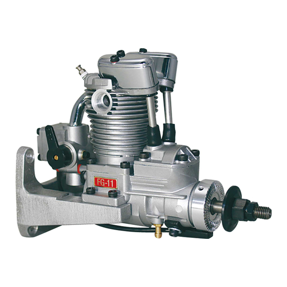
SAITO FG-11
4-Stroke Gasoline Single Engine Operating instructions
27.0mm
Body: 465g / Muffler: 50g / Ignition system: 100g / Engine mount: 110g Approx.
Approx.2,000-9,500rpm
12"x8"~13"x8"
Regular gasoline : Oil=20:1 (Volume ratio)
Approx. 7cc/min (At full throttle 8,800rpm)
*Fuel flow varies depends upon prop load. More fuel flow with larger load and less fuel flow with smaller load.
Voltage:6-8.4V higher than 1,000mA is recommended
Engine mount set
Ignition system (w/ sensor)
Spark plug [SAITO SP-1] (Attached to engine)
Muffler set
Stroke
19.0mm
Max on Gnd
Approx.8,500~8,800rpm
Static thrust
APC 13x7 Approx.1.3~1.7kgf (Depend on prop)
Applications
1set
Limit gauge (0.1t) for tappet adjustment
1set
Spanner for tappet adjusting lock nut
1pc
Hexagonal wrench set
1set
Plug wrench
Fig.1
-1-
Disp.
10.9cc
4-stroke glow 50-60 class
Outside dimensions
1pc
1pc
1set
1pc
Advertisement
Table of Contents

Related Manuals for Saito FG-11


Summary of Contents for Saito FG-11
- Page 1 SAITO FG-11 4-Stroke Gasoline Single Engine Operating instructions Thanks for buying SAITO FG-11 4-stroke gas-engine exclusively for model airplanes. In order to avoid misuse, please be sure to read well this instruction manual carefully. If there should be any deficiency, inconvenience, etc. concerning the manufacture, our company will repair them with responsibility. Any failure or trouble caused by unnecessary disassembly, modification, or other uses than those provided in the instruc- tion manual is not subject to the warranty, however. Moreover, all responsibilities for the use of the engine, and other obligations and responsibilities based on laws, regula- tions, etc. are borne by the purchaser and the user, and SAITO SEISAKUSHO CO., LTD. is exempt from any responsibilities. FG-11 is one of the smallest gas-engine among 4-stroke gas-engines which is designed based on the long seller- Glow engine “FA-62”. Taking same devices such as carb, spark plug, ignition system from exsiting single-gas engines such like “FG-21” “FG-17” “FG-14C”, durability, stability, and reliability are given as well. Notification about treatment of 4-stroke model gas-engine ◎Since valve timing is designed to get high power and high speed, the overlap range is relatively wide. So sometimes fuel get flown back from the carburetor. (It may spatter in the engine room.) ◎Since the oil for lubrication is mixed in the fuel, waste oil from the breather nipple is dirty. Depending on treatment of waste oil, it can be spattered on the plane. (Ref. Section 9) ◎Since lubrication is through breather, sometimes the oil oozes from each joint or commissure however itʼs no problem on performance. ◎Depending on the quality of the oil, sometimes there can be rust inside the crankcase. But itʼs no problem on performance as long as there are no abnormal noise or backlash. Specifications Stroke Disp. Bore 27.0mm 19.0mm 10.9cc Weight Body: 465g / Muffler: 50g / Ignition system: 100g / Engine mount: 110g Approx.
- Page 2 2. Fuel The fuel is mixture of commercial regular gasoline and reliable oil for 2-stroke. (Unleaded high-octane gasoline is not necessarily required for SAITO engine.) [Example of oil] ・ Klotz KL-200 Original Techniplate ・ Deluxe Materials PowerModel 2T-S etc. For the mixture ratio, please be sure to use “gasoline : oil =20 : 1” or richer by volume ratio. (ex. 1000ml of gasoline should be mixed with more than 50ml of oil ). Any damage caused by the fuel used, in which the oil ratio is lower than 20:1 ratio, is not warranted. Since gasoline is dangerous material, be careful of its storage, use, and transport enough. (The evaporative emission and exhaust smoke of gasoline have a harmful effect on a human body. Also, if gasoline is leaked, there is danger of fire etc.) Please note that we take no responsibility for accidents, health damages, etc which occur during storage, use and transport of gasoline. Gasoline-proof Gasoline-proof tube 3. Fuel Filter and fuel pump Pump (Option) Since commercial gasoline has many impurities, please be sure to use a reliable filter for the admission port of the gasoline-proof fuel pump (Fig.2), and in the fuel tank as well (Fig.3). Without using a filter, the performance of the carburetor is not delivered, resulting in failures. Using optional part “Filter with weight” is highly recommended. Filter with weight (Option) Fig.2 4. Fuel tank and piping Fire wall above Rubber cap for gasoline-resistant Air inhalation Air inhalation pipe Fuel level pipe Fuel tank(100~150cc) Fuel feeding pipe Fuel level to Carb nipple Gasoline-proof tube...
- Page 3 The function of each cord; (1) Plug cord (meshed high tension cord) When you put on the plug cap, insert it to the plug until you can hear clicky sound to avoid coming off during flight. And then pull the plug cap to make sure that it wonʼt come off. (2) Sensor cord (Black cord) Connect with the cord from the sensor attached to the engine. (3) Battery cord (Black/Red cord) Please use the fully charged battery that has adequate spec (6-8.4V, more than 1000mA is recommended.). Between the battery and main unit, make sure to set an ignition switch whose capacity is higher than 3A. (4) Tachometer cord (Brown/Red/Orange cord) Optional on-board tachometer can be attached. View from front Plug cap Switch (not included) Capacity: More than 3A (1)Plug cord Main unit Prop rotation (CCW) (3)Battery Cord (Red/Black) Recommended battery (4)Tachometer cord 5cell-NiMH (Brown/Red/Orange) 2cell-LiPo Voltage:6-8.4V Capacity: More than 1,000mA Advance Delay Sensor Spark timing Spark timing (2)Sensor cord Hand start (Black) easy area Fig.5 Ignition system (G17-153) ...
- Page 4 9. Engine mounting, muffler attachment, and breather waste disposal Baffle Inverted installation of the engine is recommended for lubrication however normal or side mount- ing are possible. Either way, make sure to use SAITO standard engine mount attached. As a gas-engine generates much Cool air heat, SAITO standard mount is designed to release heat effectively and vibration as well. Any other mount which is not enough robust and heat release, might cause troubles by vibration and heat. Make the firewall robust enough because this part has to endure vibration and torque caused by prop rotation. However, a test bench made of steel that doesnʼt absorb any vibration can concen- trate vibration on the engine and engine mount and there is possibility to break the engine Cowling mount in a worst case. Especially with a low load prop, engine tend to generate large vibration that Muffler outlet is very dangerous. Exhaust Therefore please use a wooden bench robust enough, never use a bench made of steel. It is preferable to apply some adhesives (such as screw lock) on the tip of each cap screw to avoid looseness when you install the engine. To ensure that cooling wind passes through the engine and muffler, the cowling should be devised. Aluminum pipe Also make the air flow outlet larger than the inlet. Building some baffles inside the cowling appropri- From Breather nipple ately will enhance the cooling efficiency. Insufficient cooling may cause engine trouble such as overheat or muffler looseness. From The muffler should be securely tightened up using two spanners.(Adhesives, such as a screw lock To outside Breather fuselage nipple agent, are effective against looseness and leakage.) Muffler right angle manifold (Option) allows muffler to set to the position as you like. Regarding the treatment of the muffler, please refer to Chapter 14. For breather treatment, attach the gasoline proof tube to the breather nipple and fix the other side of the tube on outside of the cowling. Fix a thin aluminum pipe to the outlet of the tube and bind it to the muffler outlet to diffuse the hot air together with exhaust gas into the air. Small Tissue case ...
- Page 5 *Since the richness level of the air-fuel mixture varies corresponding to the nature of the airframe, please adjust it depending on the userʼs skill. Generally, in a scale flight in which the stability of a low-speed zone is considered as important and the engine is operated slowly, adjust the air-fuel mixture to be relatively lean. In an acrobatic flight in which the early stand-up from a low speed is considered as important, adjust the air-fuel mixture to be slightly rich. (4) After the idling is set, get the throttle valve slowly fully opened. If the revolution becomes slow or goes up suddenly, adjust carefully until it changes linearly from idling to peak, by fine-tuning with the slow needle. (5) After the above adjustment is completed, open the throttle valve from idling to peak quickly. If the revolution does not achieve peak immediately but get delayed as the throttle valve is fully opened, fine-tune the main needle and perform the same process from idling to peak quickly. Repeat this carefully until the response improves. * The key to make the engine last for long life is operating with the slightly rich condition as far as it doesnʼt effect to the flight. Adjustment is needed depending on the engine attachment direction, the propeller, the fuel, the plug, the climate condition, etc. During flights, please fine-tune so that low speed, medium speed, and high speed match best with the airframe. 14. Normal operation, maintenance, and additional information (1) Just after start up the engine, perform warm up running in rich condition for about 1 minute, and just before stop run it at idling for 1 minute to cool down as well. (2) When stop the engine after the final flight of the day, be sure to stop by cutting the fuel to remove fuel from the carburetor. And remove the fuel from the tank and reserve it with special care. (3) Since the fuel contains more than 5% of oil, sometimes the exhaust valve gets dull by carbon or sludge especially in cold atmosphere. Then turn off the ignition switch and rotate the prop by electric starter. After dilute the oil content by this way, remove the fuel from inside the carb and the engine. It helps the valve to move smoothly. Or, remove the rocker cover and applying some anti-rust spray to the exhaust valve is effective as well. (4) Lubrication for piston, connecting rod, bearing or cam gear is a blow-by lubrication in which the oil in the fuel goes into the crankcase from the clearance between the cylinder and piston. Therefore the engine life is affected by the property of the fuel oil. Please use high quality oil. (5) Charge the battery for the ignition system and RC device fully. (Since the ignition system generates high tension, be careful of electrical shock.) (6) Since over closing the main needle causes overheating, adjust a little more rich than peak. Over closing leads to knocking or overheat and has an adverse effect on the connecting rod and cam gear. Where the airplane achieves peak completely at the time of ascent should be a proper peak of the engine during flight. (7) When connecting the exhaust pipe to the cylinder or attaching the prop nut, apply thin coat of silicon rubber (not exces- sively) or adhesive on the thread section before tightening. This prevents leakage or loosening. (8) Because all of SAITO gas-engines use oil-fuel mixture, there tend to be carbon buildup inside the muffler as shown in the picture. It causes some problems on the exhaust outlet and consequently reduces the power. Therefore cleaning/removing carbon every about 50 flights is recommended. Using a parts cleaning spray is effective way. Actually, it depends on the quality of the oil so when you feel the power loss, please check inside the muffler. In the case of the picture which had been done more than 70 flights, by removing the carbon buildup, the smoothness of the engine improved dramatically. ...
- Page 6 ・ Neoprene tube for gasoline(1m) [G36-155] ・ Spark plug SP-1 [G20-120] ・ Aluminum spinner nut [50-30] ・ Tappet adjusting kit [30-161] ・ Digital tachometer [G17-168] All specifications and models are subject to change without notice. http://www.saito-mfg.com SAITO SEISAKUSHO, CO., LTD. 22-7, 3-chome, Tokagi, Ichikawa-shi, Chiba prefecture 272-0024, Japan Phone: 047-378-4156 FAX: 047-378-4155...
- Page 7 SAITO FG-11 Parts List No. Description Q'ty No. Description Q'ty 01 Cylinder Valve set (In & Ex) 1set 06 Piston 46-1,-2 07 Piston pin Valve spring & Keeper & Retainer 2ea. 08 Piston pin retainer 47-1,-2,48 09 Piston ring 48 Valve retainer (Cotter) 10 Connecting rod 49 Rocker arm cover Cylinder screw set 69 Intake manifold (Intake pipe) 1set 14-1,-2 74 Muffler 15 Crankcase Muffler manifold set 1set 17 Rear cover (Back plate)
Need help?
Do you have a question about the FG-11 and is the answer not in the manual?
Questions and answers