NANO D2 Series Maintenance Service Manual
Heatless compressed air dryer
Hide thumbs
Also See for D2 Series:
- User manual (24 pages) ,
- User manual (20 pages) ,
- Maintenance service manual (29 pages)

Related Manuals for NANO D2 Series


Summary of Contents for NANO D2 Series
- Page 1 D2 SERIES HEATLESS COMPRESSED AIR DRYER MAINTENANCE & SERVICE MANUAL www.imi-precision.com...
- Page 2 Document issued created checked revision 17-100-0121 24/06/2015 Page 2...
-
Page 3: Table Of Contents
CONTENTS TITLE PAGE(S) General Information Document introduction Support & Manufacturing details Warranty guidelines Packaging Service Intervals Product Assembly Recommended Tools Dryer Shutdown Procedure Maintenance Guidelines Service ‘A’ Desiccant cartridge replacement Service ‘A’ Desiccant cartridge replacement (NDK-130 only) Service ‘A’ Inlet valve replacement 12-13 Service ‘B’... -
Page 4: General Information
This manual is copyrighted, all rights reserved. It may not, in whole or in part, be copied, photocopied, reproduced, translated, or reduced to any electronic medium or machine readable form without prior consent in writing from nano-porous solutions. It may not be distributed through the internet or computer bulletin board systems without prior consent from nano-porous solutions limited. -
Page 5: Warranty Guidelines
ES (Energy Saving) system when installed and maintained in accordance with the manufacturers guidelines. Only genuine service parts should be used and no modifications made. For further information please contact nano-porous solutions. Packaging All dryers are securely packaged in a bespoke moulded packing system. The dryer module will be secured in a horizontal position using two specifically moulded support cushions. -
Page 6: Service Intervals
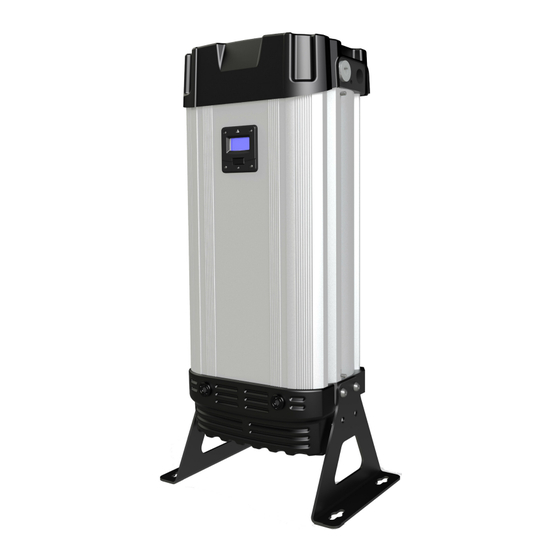
2. SERVICE INTERVALS The following table details the recommended service intervals for this product and the service kits to be used. RECOMMENDED SERVICE INTERVALS S E R V I C E TYPE 2 Years 4 Years 6 Years 8 Years 10 Years 12 Years (12000 Hrs) - Page 7 3. PRODUCT ASSEMBLY MODELS: NDL-060, 070, 080, 090, 100, 110, 120, 130 TOP COVER INLET/OUTLET (TOP) MANIFOLD ASSEMBLY DESICCANT CARTRIDGES DRYER DRYER COLUMN CONTROLLER DRYER SHROUD BOTTOM MANIFOLD ASSEMBLY SILENCER EXHAUST VALVE INLET VALVE DRYER LEGS Page 7...
-
Page 8: Product Assembly
3.1 PRODUCT ASSEMBLY MODELS: NDL-100, 110, 120, 130 TOP COVER OUTLET (TOP) MANIFOLD ASSEMBLY DESICCANT CARTRIDGES DRYER CONTROLLER DRYER COLUMN DRYER SHROUD INLET (BOTTOM) MANIFOLD ASSEMBLY SILENCER EXHAUST VALVE VALVE BLOCK DRYER LEGS INLET BLOCK Page 8... -
Page 9: Recommended Tools
Do not modify or adjust the control settings. • Only certified nano-porous solutions approved replacement parts to be used. Always check all connections for leakage and secure seating before operation. Ensure all loose parts removed during maintenance are refitted correctly before operation. -
Page 10: Service 'A' Desiccant Cartridge Replacement
7. SERVICE ‘A’ INSTRUCTIONS MODELS: NDL-050, 060, 070, 080, 090 NDL-100, 110, 120 DESICCANT CARTRIDGE REPLACEMENT NDK-060, 070, 080, 090 NDK-100, 110, 120 4x M5 SCREWS TOP COVER (Every 12,000 hrs or 24 months) 1. Ensure the dryer is shutdown and 8x M12 CAP HEAD fully depressurised before attempting any SCREWS... -
Page 11: Service 'A' Desiccant Cartridge Replacement (Ndk-130 Only)
7.1 SERVICE ‘A’ INSTRUCTIONS MODELS: NDL-130 DESICCANT CARTRIDGE REPLACEMENT NDK-130 (Every 12,000 hrs or 24 months) Please refer to Service ‘A’ instructions on page 10 of this service guide. NOTE: NDL-130 dryer has 2x cartridges per side. (See figure 2) REPLACING DESICCANT CARTRIDGES DRYER CARTRIDGE (UPPER) -
Page 12: Service 'A' Inlet Valve Replacement
8. SERVICE ‘A’ INSTRUCTIONS MODELS: NDL-100, 110, 120, 130 INLET VALVE REPLACEMENT IVK-130 1. Ensure dryer is shut down and fully depressurised before at- tempting any maintenance work. (See page 8-9) 1.1 Remove silencer box (See page 18:2) 2. Detach inlet valve tubes 1,2,3 from block. - Page 13 8. SERVICE ‘A’ INSTRUCTIONS MODELS: NDL-100, 110, 120, 130 INLET VALVE REPLACEMENT IVK-130 VALVE RIDGE DETAILS FLOW DIRECTION ARROW Figure 4. INLET VALVES SPILL PORT Figure 3. Figure 5. NOTE: The spill ports are 1.5mmØ holes within the valve block. 4.
-
Page 14: Service 'B' Outlet Valve Replacement
9. SERVICE ‘B’ INSTRUCTIONS MODELS: NDL-060, 070, 080, 090 NDL-100, 110, 120, 130 OUTLET VALVE REPLACEMENT CVK-130 (Every 24,000 hrs or 4 Years) 8x M12 CAP HEAD SCREWS MANIFOLD GASKET SEAL DU BUSH CHECK VALVE VALVE SEAT CIRCLIP Figure 1. Please refer to figure 1 1. - Page 15 9. SERVICE ‘B’ INSTRUCTIONS MODELS: NDL-060, 070, 080, 090 NDL-100, 110, 120, 130 OUTLET VALVE REPLACEMENT CVK-130 (Every 24,000 hrs or 4 Years) Figure 2. 5. Remove the valve seat by inserting the valve extraction tool through the middle of the seat valve, resting the narrow end of the tool on the dome point of the check valve.
-
Page 16: Service 'B' Inlet & Exhaust Valve Replacement
10. SERVICE ‘B’ INSTRUCTIONS MODELS: NDL-060, 070, 080, 090 INLET AND EXHAUST VALVE REPLACEMENT IVK-090 & EVK-130 & CVK-130 (Every 24,000 hrs or 4 Years) 1. Ensure the dryer is shutdown and fully depressurised before attempting any maintenance work. (See page 8-9) 2. - Page 17 10. SERVICE ‘B’ INSTRUCTIONS MODELS: NDL-060, 070, 080, 090 INLET AND EXHAUST VALVE REPLACEMENT IVK-090 & EVK-130 & CVK-130 (Every 24,000 hrs or 4 Years) BOTTOM MAN- IFOLD VALVE DIAPHRAGM EXHAUST VALVE BODIES M5 SOCKET HEAD SCREWS Figure 4. NOTE: correct valve screw tightening sequence shown.
-
Page 18: Service 'B' Exhaust Valve Replacement
11. SERVICE ‘B’ INSTRUCTIONS MODELS: NDL-100, 110, 120, 130 EXHAUST VALVE REPLACEMENT CVK-130 & EVK-130 & PVK-131 (Every 24,000 hrs or 4 Years) SILENCER 1. Ensure the dryer is shutdown and fully depressurised before attempting any maintenance work. (See page 8-9) 2. -
Page 19: Service 'B' Inlet Pilot Control Valve Replacement
12. SERVICE ‘B’ INSTRUCTIONS MODELS: NDL-100, 110, 120, 130 INLET PILOT CONTROL VALVE REPLACEMENT CVK-130 & EVK-130 & PVK-131 (Every 24,000 hrs or 4 Years) 1. Ensure dryer is shutdown and fully depressurised before maintenance work. (See page 8-9) 2. Detach solenoid plugs from solenoid coils by removing the 2x plug screws and releasing plugs. - Page 20 12. SERVICE ‘B’ INSTRUCTIONS MODELS: NDL-100, 110, 120, 130 INLET PILOT CONTROL VALVE REPLACEMENT CVK-130 & EVK-130 & PVK-131 (Every 24,000 hrs or 4 Years) 5. Remove 6x (M3x30) screws, nuts, washers and detach valves from bracket. (See figure 4) Figure 4.
-
Page 21: Service 'C' Dewpoint Sensor Replacement
13. SERVICE ‘C’ INSTRUCTIONS ES MODELS ONLY DEWPOINT SENSOR REPLACEMENT (Every 6,000 hrs or 12 months) NSK-130 M4 SCREWS CONTROLLER CHASSIS PLATE Figure 2. Figure 1. SENSOR 1. Ensure the dryer is shutdown and PLUG SCREW fully depressurised before attempting any maintenance work. - Page 22 13. SERVICE ‘C’ INSTRUCTIONS ES MODELS ONLY DEWPOINT SENSOR REPLACEMENT (Every 6,000 hrs or 12 months) NSK-130 Figure 5. Figure 6. 5. Remove the 2x fixing screws from the controller chassis plate and release the dew point sensor assembly. (See Figure 5 & 6) 6.
-
Page 23: Resetting Dryer Control
14. RESETTING DRYER CONTROLLER CONTROLLER RESET AREA Figure 1. 1. Ensure the dryer is on and running, see dryer start up procedure on page 25. 2. Place a magnet over the controller reset area shown in Figure 1 for 8-10 seconds until the dryer re-sets. -
Page 24: Manifold Tightening Sequences
15. MANIFOLD TIGHTENING SEQUENCES Top manifold Bottom manifold Page 24... -
Page 25: Dryer Start Up Procedure
16. DRYER START-UP PROCEDURE Do not allow the dryer to flow air unless powered up, switched on and cycling. Resulting effect could be cartridge contamination; requiring replacement cartridges. • Connect to mains power. • Connect all pipe work, ensure inlet & outlet valves closed. •... -
Page 26: Other Dryer Checks & Non-Serviceable Items
• Do not modify or adjust the control settings. • Only certified Nano-porous solutions approved replacement parts to be used. • Always check all connections for leakage and secure seating. • Ensure all loose parts are removed or secured to the dryer before operation. -
Page 27: Troubleshooting
18. TROUBLESHOOTING Problem Problem Cause Solution 1. Insufficient inlet pressure 1. Inlet pressure min 4 barg. If not adjust inlet pressure settings. 2. Electrical Fault 2. Ensure the power is on and the dryer front panel is illuminated; check the dryer is cycling correctly. 3. -
Page 28: Service Record & Notes
19. SERVICE RECORD & NOTES The following table allows the customer to document the service history of the product and to make notes related to each service. DRYER SERVICE RECORD PRODUCT CODE: PRODUCT SERIAL NO: ......................SERVICE TYPE SERVICED BY DATE NOTES A / B / C... - Page 29 NOTES: ........................................................................................................................................................................................................................................................................................................................ Page 29...
- Page 30 IMI Precision Engineering nano-porous solutions limited Dukesway, Team Valley Trading Estate, Gateshead NE11 0PZ. Tel: +44 (0) 1543 265 000 www.imi-precision.com...
Need help?
Do you have a question about the D2 Series and is the answer not in the manual?
Questions and answers