
Related Manuals for NANO NDL-2110


Summary of Contents for NANO NDL-2110
- Page 1 Maintenance & Service Manual heatless desiccant air dryer revision: 2021-224 document: 17-100-0141 www.n-psi.co.uk...
- Page 2 This manual is copyrighted, all rights reserved. It may not, in whole or in part, be copied, photocopied, reproduced, translated, or reduced to any electronic medium or machine readable form without prior consent in writing from nano purification solutions limited. It may not be distributed through the internet or computer bulletin board systems without prior consent from nano-purification solutions limited.
-
Page 3: Table Of Contents
MANUFACTURERS DETAILS AND SUPPORT nano-purification solutions ltd. (Manufacturer) canada - nano-purification solutions inc. address: Dukesway address 7 Petrie Street Team Valley Trading Estate Gateshead St. Catharines, NE11 0PZ Ontario United Kingdom L2P 3J6 telephone: +44 (0) 191 497 7700 Canada internet: www.n-psi.co.uk... -
Page 4: Service Intervals
1.1 SERVICE INTERVALS The following table details the recommended service intervals for this product and the service kits to be used. Recommended Service Intervals Service Type Year 1 Year 2 Year 3 Year 4 or 6.000 Hours or 12.000 Hours or 18.000 Hours or 24.000 Hours (ES Models) -
Page 5: Service Kits
1.2 SERVICE KITS Model (example) Kit number Description Service A - Replace external exhaust silencers/mufflers 40-110-GÜÜ-0000-ÜÜ BSP - 130 BSPT Exhaust Silencer element 40-110-AÜÜ-0000-ÜÜ NPT - 130 NPT Exhaust Silencer element Service B - Desiccant Replacement kit NDA-110 (x2) 40-110-ÜÜT-2110-ÜÜ 40-110-ÜÜT-2120-ÜÜ NDA-120 (x2) 40-110-ÜÜT-2130-ÜÜ NDA-130 (x2) NDA-130 (x3) 40-110-ÜÜT-3130-ÜÜ... - Page 6 Model (example) Kit number Description Service C - Valve Servicing (NOTE; you may require more than one kit) ALL MODELS EVK-6130 2 internal exhaust valves ALL MODELS IVK-6130 2 internal inlet valves ALL MODELS OVK-6130 2 internal outlet valves 40-ÜÜÜ-ÜOÜ-0000-QÜ PVKO-6130-024 24v pilot normally open operation valves 40-ÜÜÜ-ÜOÜ-0000-SÜ...
-
Page 7: Product Assembly
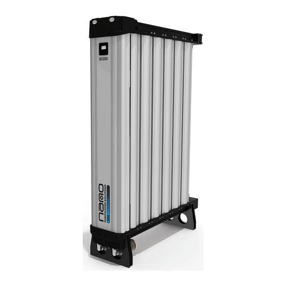
2. PRODUCT ASSEMBLY The following illustration details the basic assembly of the dryer. Model shown is an NDL-6130. Top Cover Outlet Assembly Purge Block Top Manifold PLC Display Unit Shroud Column Exhaust Manifold Inlet Manifold Bottom Cover Bottom Manifold Exhaust silencer Dryer Legs if fitted;... -
Page 8: Recommended Tools
3. RECOMMENDED TOOLS The following tools will be required to service the dryer: Strap Wrench Terminal Screw Driver 2mm, 3mm Allen Key M10, M12 Socket 8mm, 11mm, 12mm Spanner Small adjustable spanner M12 Guide pins Suitable Vacuum Cleaner Large Flat Driver 4.1 DRYER SHUT DOWN PROCEDURE Before performing any maintenance or service operations on this product, ensure the product is isolated from the compressed air supply and fully depressurised. -
Page 9: Service 'A' Instructions - Silencers/Mufflers
5. SERVICE ‘A’ INSTRUCTIONS - Silencers/Mufflers REPLACE EXTERNAL EXHAUST SILENCERS/MUFFLERS (Every year or 6,000 hours) Ensure the dryer is shut down and fully depressurised. See Page 8, section 4.1. Remove Exhaust Silencer/Mufflers from the unit and discard (figure A.1) Clean the thread and remove any sealing material debris from external exhaust elbow (figure A.3) Apply new thread sealing material to new Exhaust Silencer/Mufflers, shown in figure A.4... -
Page 10: Service 'B' Instructions - Desiccantchange
6. SERVICE ‘B’ INSTRUCTIONS - Desiccant change REPLACING DESICCANT CONTENTS (Every 2 years or 12,000 hours) Black plastic conduit Ensure the dryer is shut down and fully Tubing not present on all units. depressurised. See Page 8, section 4.1 Tubing slides in the top manifold, Remove the fixing screws from the top and around the column cover and remove cover. - Page 11 13. Remove any contaminants from the columns internal surface. 14. Using a nano suitable snow storm filler, replace the dessicant media ensuring continuous filling is maintained. A gap of 30mm must be left free at the top of each column for the column cap [figure B.5].
-
Page 12: Service 'C' Instructions - Exhaust Valves
6.1 SERVICE ‘C’ INSTRUCTIONS - Exhaust valves REPLACING EXHAUST VALVES (Every 4 years or 24,000 hours) FLOW DIRECTION ARROW VALVE RIDGE Figure C.1.1 DETAILS CO-AXIAL VALVES M10 SOCKET HEAD CAP SCREW AND WASHER EXHAUST MANIFOLD BOTTOM COVER Figure C.1 If the exhaust valves are not intented to be serviced, continue to page 13 1. -
Page 13: Service 'C' Instructions - Outlet Valves
6.2 SERVICE ‘C’ INSTRUCTIONS - Outlet valves REPLACING OUTLET NON-RETURN VALVES (Every 4 years or 24,000 hours) M10 SOCKET HEAD CAP SCREWS OUTLET MANIFOLD Figure C.2.1 Note Flow Direction on OUTLET NON the Outlet NRV RETURN VALVES TOP MANIFOLD Figure C.2 If the Outlet valves are not intented to be serviced, continue to page 14 Ensure the dryer is shut down and fully depressurised (See page 8, section 4.1). -
Page 14: Service 'C' Instructions - Inlet Valve
6.3 SERVICE ‘C’ INSTRUCTIONS - Inlet valve REPLACING INLET CONTROL VALVES (Every 4 years or 24,000 hours) Figure C.3.1 INLET VALVES 8x M10 SOCKET HEAD CAP SCREW AND WASHERS INLET MANIFOLD Figure C.3 If the Inlet valves are not intented to be serviced, continue to page 15 Ensure the dryer is shut down and fully depressurised (See page 8, section 4.1). -
Page 15: Service 'C' Instructions - Pilot Valves
6.4 SERVICE ‘C’ INSTRUCTIONS - Pilot valves REPLACING PILOT VALVES (Every 4 years or 24,000 hours) Figure C.4 If the pilot valves are not intented to be serviced, continue to start up the dryer, see page 8 Ensure the dryer is shut down and fully depressurised (See page 8, section 4.1) Disconnect and note configuration of the tubing, cables and variation between the pilot valves (Normally Open and/or Normally Closed) Remove the 4 screws to release the pilot valve assembly... -
Page 16: Service 'D' Instructions - Dew Point Sensor
7. SERVICE ‘D’ INSTRUCTIONS - Dew point sensor REPLACING OR RECALIBRATING THE DEW POINT SENSOR - ES MODELS ONLY (Every 1 year or 6,000 hours) Figure D.1.1 TOP COVER SCREWS SHROUD LATCH CONTROLLER CHASSIS PLATE 1. Ensure the dryer is shut down and fully depressurised before attempting any maintenance work. - Page 17 Figure D.3.1 Figure D.3.2 Figure D.3 Loosen the 2x M3 socket head screws from the controller chassis plate (See Figure D.3.1) and release the dew point sensor assembly. (See Figure D.3) Unscrew the dew point sensor from the sensor block and replace with the new or re-calibrated sensor making sure the mating surfaces are clean.
-
Page 18: Re-Setting The Dryer
8. RE-SETTING THE DRYER RESETTING THE PLC DISPLAY UNIT RESET AREA 1. Ensure the dryer is on and running, see dryer start up procedure on page 8. 2. Place a magnet over the controller reset area shown for 8-10 seconds until the dryer re-sets. 3. -
Page 19: Top & Bottom Manifold Tightening Sequences
9. TOP & BOTTOM MANIFOLD TIGHTENING SEQUENCES MODELS: NDL-2110, NDL-2120 & NDL-2130 MODEL(S): NDL-3130 15 8 5 13 10 1 3 11 12 4 14 6 7 16 MODEL(S): NDL-4130 Repeat torque sequence to ensure all bolts are fully seated... - Page 20 MODEL(S): NDL-6120 & NDL-6130 9.2 VALVE BLOCK TIGHTENING SEQUENCES ALL MODELS Page 20...
-
Page 21: Other Dryer Checks & Non-Serviceable Items
10. OTHER DRYER CHECKS & NON-SERVICEABLE ITEMS DAILY CHECKS Visual and functional check of the dryer should be carried out daily: • Check the dryer for any external damage. Assess and eliminate any defects found. • If the red service light appears, the dryer must be serviced. Contact the distributor service department and re- quest a dryer service kit. -
Page 22: Troubleshooting
11. TROUBLESHOOTING Problem Problem Caused Solution 1. Insufficient inlet pressure 1. Inlet pressure min 4 barg. If not adjust inlet pressure settings. 2. Electrical Fault 2. Ensure the power is on and the dryer front panel is illuminated; check the dryer is cycling correctly. 3. -
Page 23: Service Record & Notes
12. SERVICE RECORD & NOTES The following table allows the customer to document the service history of the product and to make notes related to each service. DRYER SERVICE RECORD PRODUCT SERIAL NO. PRODUCT CODE: ............................SERVICE TYPE SERVICED BY DATE NOTES A / B / C... - Page 24 Experience. Customer. Service. nano-purification solutions gateshead, united kingdom tel: +44 (0) 191 497 7700 sales@n-psi.co.uk www.n-psi.co.uk nano-purification solutions nano-purification solutions krefeld, germany st. catharines, ontario, canada tel: +49 (0) 2151 482 8218 tel: +1 905 684 6266 sales@n-psi.de support@n-psi.com www.n-psi.de www.n-psi.com...
Need help?
Do you have a question about the NDL-2110 and is the answer not in the manual?
Questions and answers