
Related Manuals for NANO D1 Series


Summary of Contents for NANO D1 Series
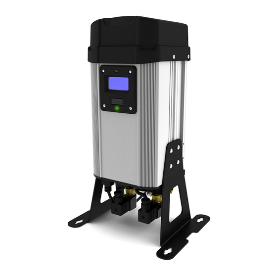
- Page 1 D1 SERIES HEATLESS COMPRESSED AIR DRYER MAINTENANCE & SERVICE MANUAL www.n-psi.co.uk...
- Page 2 Document issued created checked revision 17-100-0115 08/06/2015 17-100-0115 13/08/2018 Page 2...
-
Page 3: Table Of Contents
15-16 Resetting dryer control Manifold tightening sequences Dryer start up procedure System layout 13.1 Typical installation Hydra -D1 Series (WD1D) Process & Instrumentation diagram - WD1D-8DA-N1A~1G Other dryer checks & non-serviceable items Troubleshooting Service record & notes 23-24 Page 3... -
Page 4: General Information
Document Introduction This manual provides factory prescribed installation and maintenance procedures for a nano-purification solutions D1 Series compressed air dryer. The procedures illustrated in this document are only to be performed by fully trained competent authorised personnel. For further information regarding the procedures outlined in this document contact nano-purification solutions before proceeding. -
Page 5: General Safety
ES (Energy Saving) system when installed and maintained in accordance with the manufacturers guidelines. Only genuine service parts should be used and no modifications made. For further information please contact nano-purification solutions limited. Packaging All dryers are securely packaged in a bespoke moulded packing system. The dryer module will be secured in a horizontal position using two specifically moulded support cushions. -
Page 6: Service Intervals
2. SERVICE INTERVALS The following table details the recommended service intervals for this product and the service kits to be used. RECOMMENDED SERVICE INTERVALS S E R V I C E TYPE 2 Years 4 Years 6 Years 8 Years 10 Years 12 Years (12000 Hrs) -
Page 7: Product Assembly
MODELS: 3. PRODUCT ASSEMBLY NDL-010, 020, 030, 040, 050 TOP COVER OUTLET (TOP) MANIFOLD ASSEMBLY DESICCANT DRYER CARTRIDGES COLUMN CONTROLLER COVER (TOP) DRYER CONTROLLER DRYER SHROUD SILENCER ASSEMBLY DRYER LEGS DRYER CONTROLLER LEGS COVER (BOTTOM) VALVE BLOCK INLET (BOTTOM) MANIFOLD ASSEMBLY EXHAUST VALVES... -
Page 8: Recommended Tools
Do not modify or adjust the control settings. • Only certified nano-purification solutions approved replacement parts to be used. Always check all connections for leakage and secure seating before operation. Ensure all loose parts removed during maintenance are refitted correctly before operation. -
Page 9: Service 'A' Outlet Manifold Service
MODELS: 7. SERVICE ‘A’ INSTRUCTIONS NDL-010, 020, 030, 040, 050 NDK-010, 020, 030, 040, 050 (Every 12,000 hrs or 24 months) OUTLET MANIFOLD SERVICE (refer to figure.1) 1. Ensure the dryer is shut down and fully depressurised before attempting any maintenance 4x M5 DOME HEAD work. -
Page 10: Service 'A' Desiccant Cartridge Replacement
MODELS: 7. SERVICE ‘A’ INSTRUCTIONS NDL-010, 020, 030, 040, 050 DESICCANT CARTRIDGE REPLACEMENT AND INLET MANIFOLD SERVICE 9. Remove the 2x cartridges using the handle to withdraw them from the column. GASKET SEAL 10. Check and clean the outlet (top) manifold and dryer column as required paying particular attention to the gasket sealing areas. -
Page 11: Service 'A' Inlet Manifold Service
7. SERVICE ‘A’ INSTRUCTIONS MODELS: NDL-010, 020, 030, 040, 050 (Refer to figure 4.) Figure 3. 21. To reassemble, place the valve block on top of the inlet manifold ensuring the profiles of the screw holes line up correctly. Ensure the nitrile ball does not fall out. - Page 12 7.SERVICE ‘A’ INSTRUCTIONS MODELS: NDL-010, 020, 030, 040, 050 INLET MANIFOLD SERVICE NDK-010, 020, 030, 040, 050 (Every 12,000 hrs or 24 months) 29. Insert the new gasket seal into the gasket groove on the underside of the outlet (top) manifold ensuring it is fully retained.
-
Page 13: Service 'B' Exhaust Valve Replacement
EXHAUST VALVE REPLACEMENT (Every 24,000 hrs or 4 Years) 8. SERVICE ‘B’ INSTRUCTIONS MODELS: NDL-010, 020, 030, 040, 050 NDK-010~050 & NVK-050 VALVE SOLENOID SOLENOID PLUG SOLENOID PLUG SCREWS Figure 1. 1. Ensure the dryer is shut down and fully depressurised before attempting any maintenance work. - Page 14 8. SERVICE ‘B’ INSTRUCTIONS MODELS: NDL-010, 020, 030, 040, 050 EXHAUST VALVE REPLACEMENT NDK-010~050 & NVK-050 Figure 4. (Every 24,000 hrs or 4 Years) 4. Remove the 8x M4 long and short socket head screws and the 8x M4 spring washers and release the exhaust valve bodies and valve diaphragms from the inlet manifold.
-
Page 15: Service 'C' Outlet Valve Replacement
9. SERVICE ‘C’ INSTRUCTIONS MODELS: ES MODELS ONLY DEWPOINT SENSOR REPLACEMENT NSK-130 Figure 1. (Every 6,000 hrs or 12 months) 1. Ensure the dryer is shut down and fully depressurised before attempting any maintenance work. (See page 7-8) 2. Remove the 4x M5 screws to release the top cover and lift from assembly. - Page 16 9. SERVICE ‘C’ INSTRUCTIONS MODELS: ES MODELS ONLY DEWPOINT SENSOR REPLACEMENT NSK-130 5. Remove the dew point sensor assembly by DEW POINT SENSOR sliding the sensor bracket upwards from the BRACKET dryer shroud to expose the sensor block fixing screws. (See figure 5 & 6) DEW POINT SENSOR DEW POINT SENSOR BLOCK...
-
Page 17: Resetting Dryer Control
10. RESETTING DRYER CONTROLLER CONTROLLER RESET AREA Figure 1. 1. Ensure the dryer is on and running, see dryer start up procedure on page 19. 2. Place a magnet over the controller reset area shown in Figure 1 for 8-10 seconds until the dryer re-sets. -
Page 18: Manifold Tightening Sequences
11. MANIFOLD TIGHTENING SEQUENCE Outlet (top) manifold Inlet (bottom) manifold Page 18... -
Page 19: Dryer Start Up Procedure
The dryer will display its status and commence normal operation. • Software version number will be displayed on the screen for the first 5 seconds 13. SYSTEM LAYOUT 13.1. Typical installation D1 Series OUTLET OUTLET VALVE 0.1µm OR BETTER COALESCING FILTER... -
Page 20: Process & Instrumentation Diagram - Wd1D-8Da-N1A~1G
14. PROCESS & INSTRUMENTATION DIAGRAM 14.1. NDL-010 ~ 050 Water Separator Page 20... -
Page 21: Other Dryer Checks & Non-Serviceable Items
• Do not modify or adjust the control settings. • Only certified nano purification-solutions approved replacement parts to be used. • Always check all connections for leakage and secure seating. • Ensure all loose parts are removed or secured to the dryer before operation. -
Page 22: Troubleshooting
16. TROUBLESHOOTING Problem Problem Cause Solution 1. Insufficient inlet pressure 1. Inlet pressure min 4 barg. If not adjust inlet pressure settings. 2. Electrical Fault 2. Ensure the power is on and the dryer front panel is illuminated; check the dryer is cycling correctly. 3. -
Page 23: Service Record & Notes
17. SERVICE RECORD & NOTES The following table allows the customer to document the service history of the product and to make notes related to each service. DRYER SERVICE RECORD PRODUCT CODE: PRODUCT SERIAL NO: ......................SERVICE TYPE SERVICED BY DATE NOTES A / B / C... - Page 24 NOTES: ........................................................................................................................................................................................................................................................................................................................ Page 24...
- Page 26 Dukesway, Team Valley Trading Estate, Gateshead, Tyne and Wear, United Kingdom, NE11 0PZ Telephone: +44 (0) 191 497 7700 Internet: www.n-psi.co.uk E-mail: sales@n-psi.co.uk...
Need help?
Do you have a question about the D1 Series and is the answer not in the manual?
Questions and answers