Advertisement
Available languages
Available languages
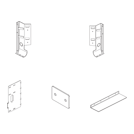
INSTRUCTIONS, CHEVY & GMC INSTALLATION KIT
CHEVY & GMC 1500 PICKUP TRUCKS, 2019-PRESENT
CHEVY & GMC 2500/3500 PICKUP TRUCKS, 2020-PRESENT
Installing and maintaining a liftgate can expose you to chemicals, including lead, which are known
to the State of California to cause cancer and birth defects or other reproductive harm. To minimize
exposure, install and maintain liftgate in a well-ventilated area and wear proper Personal protective
equipment (PPE). For more information go to www.P65Warnings.ca.gov.
MOUNTING BRACKET, LH
P/N 209329-01 (PAINTED)
P/N 209329-01G (GALVANIZED)
MAIN FRAME
MOUNTING BRACKET
P/N 209328-01 (PAINTED)
P/N 209328-01G (GALVANIZED)
QTY. 2
Estas instrucciones están disponibles en español a partir de la página 38.
LIFT CORPORATION Sht. 1 of 74 DSG#
KIT, P/N 210670-01
KIT, P/N 210670-01G (GALVANIZED)
QTY. 1
PLATE BRACKET, 3.75" X 2.5"
P/N 289545-01 (PAINTED)
P/N 289545-01G (GALVANIZED)
(T-181)
(PAINTED)
WARNING
!
QTY. 2
M-23-05
Rev. - Date: 06/20/24
MOUNTING BRACKET, RH
P/N 209329-02 (PAINTED)
P/N 209329-02G (GALVANIZED)
QTY. 1
FILLER STRIP
P/N 209325-01 (PAINTED)
P/N 209325-11 (GALVANIZED)
QTY. 3
Advertisement
Table of Contents

Related Manuals for Maxon T-181


Summary of Contents for Maxon T-181
- Page 1 M-23-05 LIFT CORPORATION Sht. 1 of 74 DSG# Rev. - Date: 06/20/24 INSTRUCTIONS, CHEVY & GMC INSTALLATION KIT (T-181) CHEVY & GMC 1500 PICKUP TRUCKS, 2019-PRESENT CHEVY & GMC 2500/3500 PICKUP TRUCKS, 2020-PRESENT KIT, P/N 210670-01 (PAINTED) KIT, P/N 210670-01G (GALVANIZED)
- Page 2 M-23-05 LIFT CORPORATION Sht. 2 of 74 DSG# Rev. - Date: 06/20/24 BOLT KIT P/N, 289488-01 BUTTONHEAD SCREW PAN HEAD SCREW HEX CAP SCREW 3/8”-16 X 1” LG. #10-24 X 3/4” LG. 3/8”-16 X 1” LG, GR5 P/N 900064-05 P/N 900753-07 P/N 900778-02 QTY.
-
Page 3: Hex Cap Screw
M-23-05 LIFT CORPORATION Sht. 3 of 74 DSG# Rev. - Date: 06/20/24 TIRE RELOCATOR KIT, P/N 289634-01 (PAINTED) TIRE RELOCATOR KIT, P/N 289634-01G (GALVANIZED) TIRE RELOCATOR (BRACKET) LOCK NUT, 1/4-20” PAN HEAD SCREW, P/N 289633-01 (PAINTED) 1/4-20 X 3/4” LG. P/N 040366 P/N 289633-01G (GALVANIZED) P/N 900002-1... -
Page 4: Circuit Breaker
M-23-05 LIFT CORPORATION Sht. 4 of 74 DSG# Rev. - Date: 06/20/24 NOTE: C2 Liftgates are shipped with the following parts kits for installing the Liftgate. The parts are stored in the main frame housing. C2 LIFTGATE SMALL PARTS & MANUAL KIT P/N 289484-01 LICENSE PLATE LIGHT... -
Page 5: Self-Tapping Screw
P/N 289484-01 CAMERA MOUNTING PLATE (GMC) CAMERA MOUNTING PLATE (TOYOTA) P/N 299602-01 P/N 299604-01 QTY. 1 QTY. 1 LOWER MOUNTING ANGLE MAXON 24/7 SUPPORT MOUNTING ANGLE DECAL P/N 289543-02 P/N 298634-01 QTY. 2 QTY. 1 BOLT BAG KIT (13180) P/N 297891-01 SELF-TAPPING SCREW 12 X 3/4”... - Page 6 M-23-05 LIFT CORPORATION Sht. 6 of 74 DSG# Rev. - Date: 06/20/24 CARGO LIGHT RELOCATION KIT, P/N 299945-01 GROMMET HOLDER GROMMET, 1-1/4” HOLE, CARGO LIGHT BRACKET P/N 210201-01 3/16’ THK, 7/8” I.D. P/N 210202-01 QTY. 2 P/N 210204-01 QTY. 2 QTY.
- Page 7 M-23-05 LIFT CORPORATION Sht. 7 of 74 DSG# Rev. - Date: 06/20/24 POWER OUTLET KIT, P/N 209844-01 (PAINTED) POWER OUTLET KIT, P/N 209844-11 (GALVANIZED) CAP SCREW OUTLET BRACKET LOCK WASHER P/N 209326-01 (PAINTED) 5/16”-18 X 3/4” LG. 5/16” X 5/64” P/N 209326-11 (GALVANIZED) P/N 900009-3 P/N 902011-3...
- Page 8 M-23-05 LIFT CORPORATION Sht. 8 of 74 DSG# Rev. - Date: 06/20/24 TRAILER PLUG KIT, P/N 209846-01 (PAINTED) TRAILER PLUG KIT, P/N 209846-11 (GALVANIZED) TRAILER PLUG BRACKET CAP SCREW LOCK WASHER P/N 209327-01 (PAINTED) 5/16”-18 X 3/4” LG. 5/16” X 5/64” P/N 209327-11 (GALVANIZED) P/N 900009-3 P/N 902011-3...
- Page 9 M-23-05 LIFT CORPORATION Sht. 9 of 74 DSG# Rev. - Date: 06/20/24 NOTE: Installer is responsible for ensuring vehicle meets Federal, State, and Local standards and regulations. BODY STRENGTH WARNING Consult vehicle body manufacturer for vehicle body strength data. Make sure the forces created by the Liftgate are within the limits prescribed by the vehicle body manufacturer.
- Page 10 M-23-05 LIFT CORPORATION Sht. 10 of 74 DSG# Rev. - Date: 06/20/24 PREPARE LIFTGATE 1. Remove mounting kits shipped with Liftgate. Refer to kits on Sheets 1 through 8. Verify mounting brackets are the correct brackets for this installation. CAUTION Liftgate will not stand upright without the shipping angles.
- Page 11 M-23-05 LIFT CORPORATION Sht. 11 of 74 DSG# Rev. - Date: 06/20/24 PREPARE LIFTGATE - Continued 4. Verify which knockouts to remove from the bottom of main frame housing (FIG. 11-1). Then, remove the knockouts as needed. KNOCKOUTS MAIN FRAME REMOVING KNOCKOUTS FROM MAIN FRAME HOUSING FIG.
- Page 12 M-23-05 LIFT CORPORATION Sht. 12 of 74 DSG# Rev. - Date: 06/20/24 BOLTING ON MAIN FRAME MOUNTING BRACKETS NOTE: Before installing main frame mounting brackets, ensure mounting bracket is positioned so the middle slot is closest to the top of the bracket. 1.
- Page 13 M-23-05 LIFT CORPORATION Sht. 13 of 74 DSG# Rev. - Date: 06/20/24 INSTALLING FILLER STRIPS NOTE: 3-piece fi ller strip must be installed prior to mounting Liftgate onto the truck. 1. Position the included fi ller strips (3) (Kit items) centered along the edge of the main frame on the Liftgate MAIN FRAME (FIG.
- Page 14 M-23-05 LIFT CORPORATION Sht. 14 of 74 DSG# Rev. - Date: 06/20/24 PREPARING PICKUP TRUCK 1. Use truck igniton key to unlock the spare tire access plug (FIG. 14-1). Remove the plug. 2. Remove spare tire from truck (FIG. 14-1). Refer to instructions in the owner’s manual and use the tools provided with truck.
- Page 15 M-23-05 LIFT CORPORATION Sht. 15 of 74 DSG# Rev. - Date: 06/20/24 CHANGING TAILLIGHT MOUNTING NOTE: Change the taillight mounting fasteners before installing Liftgate. The new fas- teners will allow both taillight lenses to be removed after Liftgate is installed. 1.
- Page 16 M-23-05 LIFT CORPORATION Sht. 16 of 74 DSG# Rev. - Date: 06/20/24 BOLTING ON SPARE TIRE RELOCATOR BRACKET NOTE: The spare tire relocator bracket provides access to the spare tire hoist after the Liftgate is installed. 1. Position relocator bracket on the inside lip of the pickup bed as shown in FIG.
- Page 17 M-23-05 LIFT CORPORATION Sht. 17 of 74 DSG# Rev. - Date: 06/20/24 INSTALLING CARGO LIGHT HOLDER & GROMMET NOTE: This section is for pickups with cargo lights on the corner posts only. 1. Remove the taillight lens from the right rear of the pickup (FIG. 17-1). CARGO LIGHT CARGO TAILLIGHT...
- Page 18 M-23-05 LIFT CORPORATION Sht. 18 of 74 DSG# Rev. - Date: 06/20/24 REMOVING POWER OUTLET NOTE: This step is for pickups with 120V power outlets on the bed sidewall. If the vehicle doesn’t have a 120V power outlet, skip this step. 1.
- Page 19 M-23-05 LIFT CORPORATION Sht. 19 of 74 DSG# Rev. - Date: 06/20/24 REMOVING TRAILER PLUG NOTE: This step is for pickups with a trailer plug on the bed sidewall. If the ve- hicle doesn’t have a trailer plug, skip this step. 1.
- Page 20 M-23-05 LIFT CORPORATION Sht. 20 of 74 DSG# Rev. - Date: 06/20/24 INSTALLING LIFTGATE NOTE: Ensure the Liftgate is in the correct position on pickup bed before marking and drilling holes. 1. Position the LH and RH mounting brack- RH MOUNTING ets (Kit items) over the cargo hooks in the BRACKET pickup bed (FIG.
- Page 21 M-23-05 LIFT CORPORATION Sht. 21 of 74 DSG# Rev. - Date: 06/20/24 INSTALLING LIFTGATE - Continued NOTE: To fi ll gaps between mounting bracket and fl oor, use 3/8” fl at washers with each bolt. HEX NUT, 3/8” 4. Let Liftgate hang from the corner posts. LOCK (2 PLACES) Allow some weight to rest on the pickup...
- Page 22 M-23-05 LIFT CORPORATION Sht. 22 of 74 DSG# Rev. - Date: 06/20/24 RELOCATING CARGO LIGHT 1. Position the cargo light bracket (Kit item) over the cargo light opening in the RH main frame mounting bracket (FIG. 22-1) and secure with #12 self-drilling screws (Kit items).
- Page 23 M-23-05 LIFT CORPORATION Sht. 23 of 74 DSG# Rev. - Date: 06/20/24 RELOCATING 120V POWER OUTLET NOTE: This step is for pickups with 120V power outlets on the bed sidewall. If the vehicle doesn’t have a 120V power outlet, skip this step. 1.
- Page 24 M-23-05 LIFT CORPORATION Sht. 24 of 74 DSG# Rev. - Date: 06/20/24 RELOCATING TRAILER PLUG NOTE: This step is for pickups with a trailer plug on the bed sidewall. If the ve- hicle doesn’t have a trailer plug, skip this step. 1.
- Page 25 M-23-05 LIFT CORPORATION Sht. 25 of 74 DSG# Rev. - Date: 06/20/24 CHECKING ACCESS TO SPARE TIRE CAUTION Do not use a battery charger for connecting power to Liftgate power cables. 1. Connect power from a 12 volt truck battery to the Liftgate power cables extending from the back of main frame housing.
- Page 26 M-23-05 LIFT CORPORATION Sht. 26 of 74 DSG# Rev. - Date: 06/20/24 CHECKING ACCESS TO SPARE TIRE - Continued LH COLUMN 4. Remove the correct black (DRIVER SIDE) plastic plugs from the cover FRONT OF LIFTGATE and main frame (FIG. 26-1). ACCESS HOLE FOR CHEVY &...
-
Page 27: Routing Power Cables
M-23-05 LIFT CORPORATION Sht. 27 of 74 DSG# Rev. - Date: 06/20/24 ROUTING POWER CABLES 1. Remove the small parts and manual kit from the housing. Refer to Sheet 4 for con- tents of the kits. 2. Install circuit breaker (FIG. 27-1) inside the en- gine compartment near truck battery (+) termi- nal and away from moving parts. - Page 28 M-23-05 LIFT CORPORATION Sht. 28 of 74 DSG# Rev. - Date: 06/20/24 C2 PICKUP LIFTGATE HYDRAULIC & ELECTRICAL SYSTEMS DIAGRAM FIG. 28-1...
- Page 29 M-23-05 LIFT CORPORATION Sht. 29 of 74 DSG# Rev. - Date: 06/20/24 INSTALLING CAMERA AND SENSORS (IF EQUIPPED) 1. Note camera mounting bracket and sensor mounting bracket locations MAIN FRAME on main frame housing (FIG. 29-1). HOUSING SENSOR MOUNTING BRACKET (4 PLACES) CAMERA MOUNTING BRACKET...
- Page 30 M-23-05 LIFT CORPORATION Sht. 30 of 74 DSG# Rev. - Date: 06/20/24 INSTALLING CAMERA AND SENSORS (IF EQUIPPED) - Continued 3. OEM camera can be attached to NYLON NUT, #10-24 CAMERA SCREWS P/N 901003 the camera mounting bracket in two (2 PLACES) (4 PLACES) ways.
- Page 31 M-23-05 LIFT CORPORATION Sht. 31 of 74 DSG# Rev. - Date: 06/20/24 INSTALLING CAMERA AND SENSORS (IF EQUIPPED) - Continued 4. Adjust camera angle (FIG. 31-1) by CAMERA MOUNTING BRACKET AND OEM bending camera mounting bracket until CAMERA image on backup camera display screen adheres to standard in FMVSS 111.
- Page 32 M-23-05 LIFT CORPORATION Sht. 32 of 74 DSG# Rev. - Date: 06/20/24 INSTALLING CAMERA AND SENSORS (IF EQUIPPED) - Continued 8. Remove camera knockout and sensor plugs (if required) from housing cover (FIG. 32-1). HOUSING COVER SENSOR PLUGS (4 PLACES) CAMERA KNOCKOUT REMOVING HOUSING COVER SENSOR PLUGS AND CAMERA KNOCKOUT...
- Page 33 M-23-05 LIFT CORPORATION Sht. 33 of 74 DSG# Rev. - Date: 06/20/24 INSTALL LOWER MOUNTS CAUTION Liftgate can be severely damaged by connecting electric welder ground lead to the wrong place. To prevent damage, always connect ground lead directly to compo- nent being welded and as close as possible to the weld.
- Page 34 M-23-05 LIFT CORPORATION Sht. 34 of 74 DSG# Rev. - Date: 06/20/24 COMPLETE LIFTGATE INSTALLATION BREATHER PLUG CAUTION Hydraulic system is fi lled at the factory with correct amount of oil. It is unnecessary to add more oil except as required for periodic maintenance of the liftgate.
- Page 35 M-23-05 LIFT CORPORATION Sht. 35 of 74 DSG# Rev. - Date: 06/20/24 COMPLETE LIFTGATE INSTALLATION - Continued 6. To use the drop-away platform feature, install drop pin and 3/8”-16 lock nut (Kit items) on the bottom of RH column (FIG. 35-1). Tighten lock nut securely. DROP PIN LOCK NUT, 3/8”-16 (P/N 901016-4)
- Page 36 M-23-05 LIFT CORPORATION Sht. 36 of 74 DSG# Rev. - Date: 06/20/24 TEST OPERATION OF LIFTGATE WARNING Keep all foreign objects out of the Liftgate main frame and away from pinch points at all times when operating Liftgate. NOTE: The LIFTGATE ACTIVATED LED illuminates when Liftgate power is on.
- Page 37 M-23-05 LIFT CORPORATION Sht. 37 of 74 DSG# Rev. - Date: 06/20/24 TEST OPERATION OF LIFTGATE - Continued 9. With the platform closed, use lock pin to secure latch to the pin on the platform (FIG. 37-1). LATCH PLATFORM PLATFORM LOCK PIN SECURING THE PLATFORM (RH SIDE)
- Page 38 LIFT CORPORATION Pág. 38 de 74 DSG# Rev. - Fecha: 06/20/24 INSTRUCCIONES, KIT DE INSTALACIÓN PARA CHEVY Y GMC (T-181) CAMIONETAS PICK UP CHEVY Y GMC 1500, 2019 - PRESENTE CAMIONETAS PICK UP CHEVY Y GMC 2500/3500, 2020 - PRESENTE...
- Page 39 MS-23-05 LIFT CORPORATION Pág. 39 de 74 DSG# Rev. - Fecha: 06/20/24 KIT DE TORNILLOS N/P, 289488-01 TORNILLO TORNILLO CON CABEZA TORNILLO DE CABEZA CABEZA DE BOTÓN HEXAGONAL REDONDA 3/8”- 16 X 1” 3/16”-16 X 1” DE LARGO, #10-24 X 3/4” DE LARGO DE LARGO GRADO 5 N/P 900753-07...
- Page 40 MS-23-05 LIFT CORPORATION Pág. 40 de 74 DSG# Rev. - Fecha: 06/20/24 KIT PARA REUBICACIÓN DE NEUMÁTICO, N/P 289634-01 (PINTADO) KIT PARA REUBICACIÓN DE NEUMÁTICO, N/P 289634-01G (GALVANIZADO) SOPORTE PARA LA TORNILLO DE CABEZA TUERCA DE SEGURIDAD, REDONDA, 1/4-20 X 3/4” LGO. 1/4-20”...
- Page 41 MS-23-05 LIFT CORPORATION Pág. 41 de 74 DSG# Rev. - Fecha: 06/20/24 NOTA: Los Elevadores C2 se envían con los siguientes kits de partes para instalar el elevador. Las partes se guardan en la carcasa del bastidor principal. KIT DE MANUAL Y PARTES PEQUEÑAS PARA ELEVADOR C2 N/P 289484-02 INSTALACIÓN DE LUCES...
- Page 42 MS-23-05 LIFT CORPORATION Pág. 42 de 74 DSG# Rev. - Fecha: 06/20/24 KIT DE MANUAL Y PARTES PEQUEÑAS PARA ELEVADOR C2 (Cont.) N/P 289484-02 PLACA DE MONTAJE PARA LA CÁMARA (GMC) PLACA DE MONTAJE PARA LA N/P 299602-01 CÁMARA (TOYOTA) CANT.
- Page 43 MS-23-05 LIFT CORPORATION Pág. 43 de 74 DSG# Rev. - Fecha: 06/20/24 KIT DE REUBICACIÓN DE LUZ DE CARGA, N/P 299945-01 SOPORTE DEL OJAL OJAL, AGUJERO DE 1-1/4”, SOPORTE DE LUZ DE CARGA N/P 210201-01 GRUESO 3/16’, 7/8” D.I. N/P 210202-01 CANT.
- Page 44 MS-23-05 LIFT CORPORATION Pág. 44 de 74 DSG# Rev. - Fecha: 06/20/24 KIT PARA TOMA DE CORRIENTE, N/P 209844-01 (PINTADO) KIT PARA TOMA DE CORRIENTE, N/P 209844-11 (GALVANIZDA) ARANDELA DE PRESIÓN SOPORTE PARA TOMA TORNILLO DE DE CORRIENTE 5/16” X 5/64” CABEZA HEX.
- Page 45 MS-23-05 LIFT CORPORATION Pág. 45 de 74 DSG# Rev. - Fecha: 06/20/24 KIT DE ENCHUFE PARA TRÁILER, N/P 209846-01 (PINTADO) KIT DE ENCHUFE PARA TRÁILER, N/P 209846-11 (GALVINAZADO) SOPORTE DE ENCHUFE TORNILLO DE CABEZA HEX. ARANDELA DE PARA TRÁILER 5/16”-18 X 3/4” LGO. PRESIÓN N/P 209327-01 (PINTADO) N/P 900009-3...
- Page 46 MS-23-05 LIFT CORPORATION Pág. 46 de 74 DSG# Rev. - Fecha: 06/20/24 NOTA: El instalador es el responsable de asegurarse que el vehículo cumpla con las leyes y estándares federales, estatales y Locales. CAPACIDAD DE LA CARROCERÍA ADVERTENCIA Consulte la capacidad de la carrocería de su vehículo con el fabricante de la carrocería.
- Page 47 MS-23-05 LIFT CORPORATION Pág. 47 de 74 DSG# Rev. - Fecha: 06/20/24 PREPARAR EL ELEVADOR 1. Retire los kits de montaje enviados con el elevador. Consulte los kits en las Páginas 39 a 45. Verifi que que los soportes de montaje sean los so- portes correctos para esta instalación.
- Page 48 MS-23-05 LIFT CORPORATION Pág. 48 de 74 DSG# Rev. - Fecha: 06/20/24 PREPARAR EL ELEVADOR - Cont. 4. Verifi que cuáles agujeros se deben perforar en la parte inferior de la carcasa en el bastidor principal (FIG. 48-1). Después remueva los que sean necesarios. AGUJEROS PARA PERFORAR BASTIDOR...
- Page 49 MS-23-05 LIFT CORPORATION Pág. 49 de 74 DSG# Rev. - Fecha: 06/20/24 ATORNILLAR SOPORTES DE MONTAJE DEL BASTIDOR PRINCIPAL NOTA: Antes de instalar los soportes de montaje del bastidor principal, asegúrese de que el soporte de montaje esté posicionado de manera que la ranura central esté...
- Page 50 MS-23-05 LIFT CORPORATION Pág. 50 de 74 DSG# Rev. - Fecha: 06/20/24 INSTALAR TIRAS DE RELLENO NOTA: Las 3 piezas de tiras de relleno deben ser instaladas antes de montar el elevador al vehículo. 1. Posicione las 3 tiras de relleno includas (arts.
- Page 51 MS-23-05 LIFT CORPORATION Pág. 51 de 74 DSG# Rev. - Fecha: 06/20/24 PREPARAR LA CAMIONETA PICKUP 1. Utilice la llave para encender la camioneta para desbloquear el tapón de acceso al neumático de repuesto (FIG. 51-1). Retire el tapón. 2. Retire el neumático de repuesto de la camioneta (FIG.
- Page 52 MS-23-05 LIFT CORPORATION Pág. 52 de 74 DSG# Rev. - Fecha: 06/20/24 CAMBIAR EL MONTAJE DE LA LUZ POSTERIOR NOTA: Cambie los sujetadores de montaje de la luz posterior antes de instalar el elevador. Los nuevos sujetadores permitirán que se retiren ambos lentes de la luz posterior después de que se instale el elevador.
- Page 53 MS-23-05 LIFT CORPORATION Pág. 53 de 74 DSG# Rev. - Fecha: 06/20/24 ATORNILLAR EL SOPORTE PARA REUBICACIÓN DEL NEUMÁTICO DE REPUESTO NOTA: El soporte para reubicación del neumático de repuesto provee acceso al mecanismo elevador del neumático de repuesto después de que se instala el elevador. 1.
- Page 54 MS-23-05 LIFT CORPORATION Pág. 54 de 74 DSG# Rev. - Fecha: 06/20/24 INSTALAR SOPORTE DE LUZ DE CARGA Y OJAL NOTA: Esta sección solo es para pickups con luces de carga en los postes de esquina. 1. Retire la lente de la luz posterior de lado AGUJERO DE LUZ DE derecho posterior de camioneta (FIG.
- Page 55 MS-23-05 LIFT CORPORATION Pág. 55 de 74 DSG# Rev. - Fecha: 06/20/24 RETIRAR TOMA DE CORRIENTE NOTA: Este paso es para pickups con toma de corriente de 120V en la pared lateral de la cama del vehículo. Si el vehículo no tiene toma de corriente de 120V, omita este paso.
- Page 56 MS-23-05 LIFT CORPORATION Pág. 56 de 74 DSG# Rev. - Fecha: 06/20/24 RETIRAR ENCHUFE DE REMOLQUE NOTA: Este paso es para pickups con enchufe de remolque en la pared lateral de la cama del vehículo. Si el vehículo no tiene un enchufe de remolque, omita este paso.
- Page 57 MS-23-05 LIFT CORPORATION Pág. 57 de 74 DSG# Rev. - Fecha: 06/20/24 INSTALAR EL ELEVADOR NOTA: Verifi que que el elevador esté en la posición correcta en la cama del pickup antes de marcar y perforar agujeros. SOPORTE 1. Coloque los soportes de montaje DE MONTAJE izquierdo y derecho (art.
- Page 58 MS-23-05 LIFT CORPORATION Pág. 58 de 74 DSG# Rev. - Fecha: 06/20/24 INSTALAR EL ELEVADOR - Cont. NOTA: Para llenar las brechas entre el soporte de montaje y el piso, utilice arandelas planas de 3/8” [9 mm] con cada perno. TUERCA HEX.
- Page 59 MS-23-05 LIFT CORPORATION Pág. 59 de 74 DSG# Rev. - Fecha: 06/20/24 REUBICAR LUZ DE CARGA 1. Coloque el soporte de luz de carga (art. del kit) sobre la apertura de la luz de carga en el soporte de montaje del bastidor principal de lado derecho (FIG.
- Page 60 MS-23-05 LIFT CORPORATION Pág. 60 de 74 DSG# Rev. - Fecha: 06/20/24 REUBICAR LA TOMA DE CORRIENTE DE 120V NOTA: Este paso es para pickips con toma de corriente de 120V en la pared lateral de la cama del vehículo. Si el vehículo no tiene una toma de corriente de 120V, omita este paso.
- Page 61 MS-23-05 LIFT CORPORATION Pág. 61 de 74 DSG# Rev. - Fecha: 06/20/24 REUBICAR ENCHUFE DE REMOLQUE NOTA: Este paso es para pickups con enchufe de remolque en la pared lateral de la cama del vehículo. Si el vehículo no tiene un enchufe de remolque, omita este paso.
- Page 62 MS-23-05 LIFT CORPORATION Pág. 62 de 74 DSG# Rev. - Fecha: 06/20/24 VERIFICAR EL ACCESO AL NEUMÁTICO DE REPUESTO PRECAUCIÓN No use un cargador de batería para conectar la energía a los cables de alimentación del Elevador. 1. Conecte la energía de una batería de 12 voltios para camioneta a los cables de alimentación del Elevador que salen de la parte posterior de ELEVADOR...
- Page 63 MS-23-05 LIFT CORPORATION Pág. 63 de 74 DSG# Rev. - Fecha: 06/20/24 VERIFICAR EL ACCESO AL NEUMÁTICO DE REPUESTO - Cont. 4. Retire los tapones correctos COLUMNA IZQ. de plástico de color negro (LADO DEL CONDUCTOR) de la carcasa y el bastidor (FIG.
- Page 64 MS-23-05 LIFT CORPORATION Pág. 64 de 74 DSG# Rev. - Fecha: 06/20/24 CANALIZAR CABLES DE ALIMENTACIÓN 1. Retire el kit de partes pequeñas y manuales de la carcasa del bastidor. Consulte los contenidos de los kits en la Página 4. 2.
- Page 65 MS-23-05 LIFT CORPORATION Pág. 65 de 74 DSG# Rev. - Fecha: 06/20/24 VÁLVULA SOLENOIDE TIERRA A ENSAMBLE DE BOMBA/MOTOR INTERRUPTOR BATERÍA DISYUNTOR SOLENOIDE DE CAMIÓN 150A CABLE #4 TIERRA A BASTIDOR DE CAMIÓN TIERRA TIERRA A BOMBA/MOTOR VERDE ROJO (ELEVAR) INTERRUPTOR NEGRO (TIERRA) CAFÉ...
- Page 66 MS-23-05 LIFT CORPORATION Pág. 66 de 74 DSG# Rev. - Fecha: 06/20/24 INSTALAR LA CÁMARA Y LOS SENSORES (SI SE EQUIPAN) 1. Observe las ubicaciones de montaje de la cámara y el soporte de montaje CARCASA DEL BASTIDOR del sensor en la carcasa del bastidor PRINCIPAL principal (FIG.
- Page 67 MS-23-05 LIFT CORPORATION Pág. 67 de 74 DSG# Rev. - Fecha: 06/20/24 INSTALAR LA CÁMARA Y LOS SENSORES (SI SE EQUIPAN) - Cont. TUERCA DE NAILON, #10-24 3. La cámara OEM se puede fi jar al N/P 901003 TORNILLOS DE soporte de montaje de la cámara (4 LUGARES) LA CÁMARA OEM...
- Page 68 MS-23-05 LIFT CORPORATION Pág. 68 de 74 DSG# Rev. - Fecha: 06/20/24 INSTALAR LA CÁMARA Y LOS SENSORES (SI SE EQUIPAN) - Cont. 4. Ajuste el ángulo de la cámara (FIG. 68-1) SOPORTE DE MONTAJE PARA LA CÁMARA doblando el soporte de montaje para la Y CÁMARA OEM cámara hasta que la imagen en la pantalla de la cámara de retroceso se adhiera al...
- Page 69 MS-23-05 LIFT CORPORATION Pág. 69 de 74 DSG# Rev. - Fecha: 06/20/24 INSTALAR LA CÁMARA Y LOS SENSORES (SI SE EQUIPAN) - Cont. 8. Retire el agujero de la cámara señalado para perforarse y los tapones de los sensores (si se requiere) de la cubierta de la carcasa (FIG.
- Page 70 MS-23-05 LIFT CORPORATION Pág. 70 de 74 DSG# Rev. - Fecha: 06/20/24 INSTALAR PLACAS DE MONTAJE INFERIORES PRECAUCIÓN El Elevador hidráulico se puede dañar severamente si la conexión a tierra de la solda- dora eléctrica está conectada en el lugar incorrecto. Para prevenirlo, siempre conecte el cable de tierra al componente que se está...
- Page 71 MS-23-05 LIFT CORPORATION Pág. 71 de 74 DSG# Rev. - Fecha: 06/20/24 FINALIZAR LA INSTALACIÓN DEL ELEVADOR TAPÓN CON PRECAUCIÓN RESPIRADERO El sistema hidráulico se llena en la fábrica con la cantidad correcta de aceite. No es necesario añadir más aceite a menos de que se requiera como parte del mantenimiento periódico del Elevador.
- Page 72 MS-23-05 LIFT CORPORATION Pág. 72 de 74 DSG# Rev. - Fecha: 06/20/24 FINALIZAR INSTALACIÓN DEL ELEVADOR - Cont. 6. Para utilizar la funcion de plata- forma desplegable, instale el pasador de caída y una tuerca de seguridad de 3/8”-16 (arts. del kit) en la parte inferior de la columna derecha (FIG.
- Page 73 MS-23-05 LIFT CORPORATION Pág. 73 de 74 DSG# Rev. - Fecha: 06/20/24 COMPROBAR FUNCIONAMIENTO DEL ELEVADOR ADVERTENCIA Mantenga todos los objetos extraños fuera del bastidor principal del elevador y lejos de los puntos de pellizco en todo momento al operar el elevador. NOTA: La luz LED de ELEVADOR ACTIVADO se ilumina cuando el elevador está...
- Page 74 MS-23-05 LIFT CORPORATION Pág. 74 de 74 DSG# Rev. - Fecha: 06/20/24 COMPROBAR FUNCIONAMIENTO DEL ELEVADOR - Cont. 9. Con la plataforma cerrada, use el pasador de bloqueo para asegurar el pestillo al pasador de la plataform (FIG. 74-1). PESTILLO PLATAFORMA PASADOR DEL ENGANCHE...
Need help?
Do you have a question about the T-181 and is the answer not in the manual?
Questions and answers