Maxon DMD-22 Operation Manual
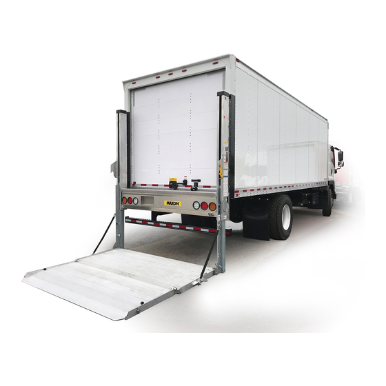
Tool truck
Hide thumbs
Also See for DMD-22:
- User maintenance manual (40 pages) ,
- Instruction manual (33 pages) ,
- Maintenance manual (51 pages)
Table of Contents
Advertisement
Quick Links
KEEP THIS MANUAL INSIDE OF VEHICLE
Register your liftgate online at http://www.maxonlift.com/support/product-registration.
For a free copy of other manuals that pertain to these liftgate models, please visit our
website at www.maxonlift.com or call Customer Service at (800) 227-4116.
To fi nd maintenance & parts information for your Tool Truck DMD Liftgate, go to
www.maxonlift.com. Click the PRODUCTS, RAILIFT & DMD buttons. Open the Main-
tenance Manual in the PRODUCT DOCUMENTATION window. For parts, click on the
PARTS PORTAL, RAILIFT & DMD buttons.
SEPTEMBER 2022
© MAXON Lift Corp. 2022
M-21-02
Advertisement
Table of Contents

Related Manuals for Maxon DMD-22


Summary of Contents for Maxon DMD-22
- Page 1 To fi nd maintenance & parts information for your Tool Truck DMD Liftgate, go to www.maxonlift.com. Click the PRODUCTS, RAILIFT & DMD buttons. Open the Main- tenance Manual in the PRODUCT DOCUMENTATION window. For parts, click on the PARTS PORTAL, RAILIFT & DMD buttons. © MAXON Lift Corp. 2022...
-
Page 3: Table Of Contents
TABLE OF CONTENTS WARNINGS ................4 LIFTGATE TERMINOLOGY .............5 RECOMMENDED DAILY OPERATION CHECKS ....6 DECALS .................8 DECALS & PLATES ..............10 FORKLIFT ADVISORY ............11 OPERATION ................12 UNFOLDING THE PLATFORM ..........12 LOADING VEHICLE ..............16 LOWERING THE PLATFORM ..........16 POSITIONING LOAD ...............16 RAISING & UNLOADING PLATFORM ........18 UNLOADING VEHICLE ............20 POSITIONING LOAD ...............20 LOWERING &... -
Page 4: Warnings
11921 Slauson Ave Santa Fe Springs, CA 90670 (800) 227-4116 2. Do not exceed rated load capacity of 2200 lb for Tool Truck DMD-22 Liftgate. 3. Do not allow any part of your body to be placed under, within, or around any portion of the moving Liftgate or its mechanisms, or in a position that would trap them between the platform and the fl... -
Page 5: Liftgate Terminology
LIFTGATE TERMINOLOGY LH COLUMN RH COLUMN MAIN FRAME RUNNER PLATFORM PLATFORM CART STOP FLIPOVER CART STOP FLIPOVER... -
Page 6: Recommended Daily Operation Checks
RECOMMENDED DAILY OPERATION CHECKS NOTE: Before you check the Liftgate, park vehicle on fl at ground and set the parking brake. NOTE: If any of the following operation checks reveal a need to service or repair Liftgate, do not operate the Liftgate until a qualifi... - Page 7 Use the operation instructions in this manual to operate the Liftgate through one cycle without a load on the platform. Raise the platform to vehicle bed height. Next, lower the platform to ground level. When raising and lowering platform, listen for unusual noises and look for a “jerking”...
-
Page 8: Decals
DECALS NOTE: Ensure there is no residue, dirt, or corrosion where decals are attached. If necessary, clean surface before attaching decals. CAPACITY DECAL P/N 220388-03 DECAL “B” P/N 211630-01 DECAL “A” P/N 211630-01 WARNING DECAL FAMILY OWNED DECAL P/N 299274-01 P/N 283445-01 RUNNER ARROW COLUMN ARROW... - Page 9 DECAL SHEET P/N 211630-01...
-
Page 10: Decals & Plates
NOTE: Preferred decal layout is shown. Decals on the Liftgate are attached at the factory, except for the 24/7 SUPPORT decal. The 24/7 SUPPORT decal is placed at customer’s or installer’s preference. MAXON 24/7 SUPPORT DECAL P/N 298634-01 SERIAL PLATE... -
Page 11: Forklift Advisory
FORKLIFT ADVISORY WARNING Keep forklift OFF of platform. FIG. 11-1 FIG. 11-2... -
Page 12: Operation
OPERATION UNFOLDING THE PLATFORM NOTE: Do RECOMMENDED DAILY OPERATION CHECKS at the beginning of this manual. 1. Raise platform stop off transit hook (FIGS. 12-1 and 12-1A) by pushing the control switch UP button (FIGS. 12-1 and 12-1B). PLATFORM PLATFORM TRANSIT STOP HOOK... - Page 13 2. Rotate transit hook away from platform stop (FIG. 13-1A). Push control switch DOWN button (FIG. 13-1B) to lower the platform until platform stop clears transit hook and arrow decals align on column and runner (FIGS. 13-1 and 13-1C). PLATFORM TRANSIT HOOK PLATFORM...
- Page 14 UNFOLDING THE PLATFORM - Continued 3. Hold power closer button and control switch DOWN button (FIGS. 14-1A and 14-1B) at the same time to unfold platform (FIG. 14-1). CONTROL SWITCH (DOWN) FIG. 14-1A PLATFORM POWER CLOSER BUTTON FIG. 14-1B UNFOLDING PLATFORM FIG.
- Page 15 4. Push latch in direction of arrow to unlock and unfold fl ipover (FIGS. 15-1 and 15-1A). LATCH FLIPOVER FIG. 15-1A UNFOLDING FLIPOVER FIG. 15-1...
-
Page 16: Loading Vehicle
LOADING VEHICLE LOWERING THE PLATFORM Press control switch DOWN button to lower platform (FIG. 16-1A). Release DOWN button when platform reaches the ground (FIG. 16-1). CONTROL SWITCH (DOWN) FIG. 16-1A FIG. 16-1 POSITIONING LOAD WARNING A load should never extend past the edges of the platform. Do not place unstable loads on platform and do not allow load to exceed lifting capacity of Liftgate. - Page 17 2. Using your foot, push the rear cart stop opener block to the REAR CART STOP open position (FIG. 17-1). (OPEN) OPENER GUIDE RAIL BLOCK (REF) OPENING REAR CART STOP FIG. 17-1 3. Place all loads against the rear cart stop, with heaviest part toward the truck body as shown in FIG.
-
Page 18: Raising & Unloading Platform
LOADING VEHICLE - Continued POSITIONING LOAD - Continued 4. To open front cart stop, push latch LATCH in direction shown in FIG. 18-1. Lift cart stop to open position (FIG. 18-1). CART STOP OPENING FRONT CART STOP (RH VIEW OF FLIP OVER) FIG. - Page 19 2. Using your foot, push the rear cart stop opener block to the closed position (FIG. 19-1). REAR CART STOP (CLOSED) OPENER BLOCK CLOSING REAR CART STOP FIG. 19-1 3. Carefully move the load into vehicle (FIG. 18-2). 4. To close front cart stop, push latch in direction shown in FIG.
-
Page 20: Unloading Vehicle
UNLOADING VEHICLE POSITIONING LOAD 1. Press control switch DOWN button to lower platform (FIG. 20-1A). Release DOWN button when platform reaches the ground (FIG. 20-1). CONTROL SWITCH (DOWN) FIG. 20-1A LOWERING PLATFORM FIG. 20-1 2. To open front cart stop, push LATCH latch in direction shown in FIG. - Page 21 3. For roll-off protection, push latch (FIG. 21-1) in direction of arrow and rotate the RH guide rail to the inboard position (FIG. 21-1). Repeat for rail on LH side of platform. GUIDE RAIL (INBOARD POSITION) LATCH GUIDE RAIL (OUTBOARD POSITION) ROTATING GUIDE RAIL TO INBOARD POSITION (RH VIEW OF PLATFORM) FIG.
- Page 22 UNLOADING VEHICLE - Continued POSITIONING LOAD - Continued WARNING A load should never extend past the edges of the platform. Do not place unstable loads on platform and do not allow load to exceed lifting capacity of Liftgate. If standing on platform, do not allow your feet to extend beyond inboard edge of platform.
- Page 23 5. Load the platform at bed level (FIG. 23-1) as follows. Push load out of the vehicle to correct position on the platform. Place all loads as close as possible to the inboard edge of the platform with heaviest part toward the ve- hicle body as shown in FIG.
-
Page 24: Lowering & Unloading Platform
UNLOADING VEHICLE - Continued LOWERING & UNLOADING PLATFORM WARNING Before lowering platform, make sure area surrounding platform is clear of people and objects. If standing on platform, do not allow your feet to extend beyond inboard edge of platform. 1. Press control switch DOWN button (FIG. - Page 25 3. Carefully move load off platform (FIG. 25-1) and then move it to a place where it will not become a hazard for people and other vehicles. If there is more to unload from vehicle, repeat the previous UNLOADING VEHICLE steps for each load. When unloading is fi...
-
Page 26: Stowing Platform
STOWING PLATFORM NOTE: Ensure platform is stowed under hydraulic pressure. 1. With platform on the ground (FIG. 26-1), push latch in direction of arrow and rotate the RH guide rail to the outboard position (FIG. 26-1A). Repeat for rail on LH side of platform. RH GUIDE RAIL (INBOARD POSITION) LATCH... - Page 27 3. Press control switch UP button to raise platform until arrow decals are aligned on runner and column (FIGS. 27-1 and 27-1A). CONTROL SWITCH (UP) FIG. 27-1A ARROW DECALS FIG. 27-1 4. Fold and lock fl ipover. (FIGS. 27-2 and 27-2A). LATCH IN LOCK POSITION FIG.
- Page 28 STOWING PLATFORM - Continued CAUTION Folding the platform with hydraulic closer requires 2 hands on the controls. This helps prevent injuries. 5. Using one hand for control switch (FIG. 28-1A) and one hand for POWER CLOSER button (FIG. 28-1B), press POWER CLOSER button and UP button together until platform is folded (FIG.
- Page 29 6. Press control switch UP button to raise platform (FIGS. 29-1 and 29-1A) until it is clear of transit hook (FIG. 29-1B). Final platform position is shown in FIG. 29-1C. TRANSIT HOOK PLATFORM FIG. 29-1B CONTROL SWITCH (UP) FIG. 29-1A FIG.
Need help?
Do you have a question about the DMD-22 and is the answer not in the manual?
Questions and answers