Advertisement
Quick Links
where inspiration flows
This instruction booklet covers models:
ELE-148D/2/SQ-CP
Wedmore Road, Cheddar, Somerset, England BS27 3EB
tel 01934 744466.
aftersales
www.vado.com
Version 1, 1-3-20
Vado
fax 01934 744345
vado.com
@
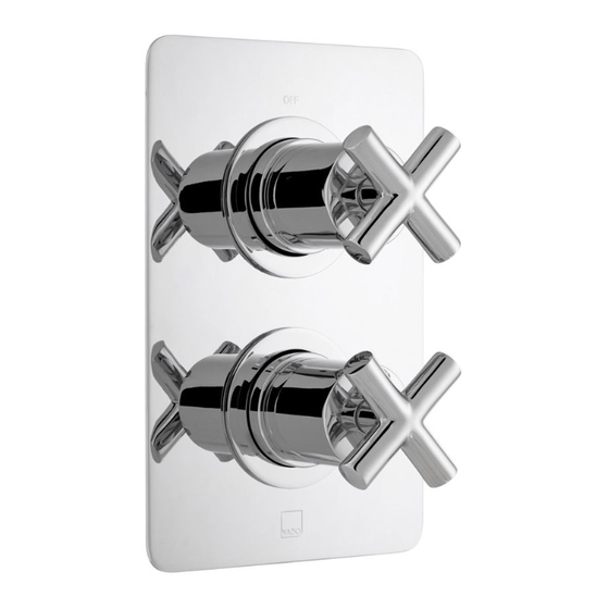
ELEMENTS
2 Outlet, 2 Handle Concealed Thermostatic Valve
Installation Guide
ELE-148D/2/SQ-CP
Keep for future reference
Advertisement

Related Manuals for VADO ELEMENTS ELE-148D/2/SQ-CP


Summary of Contents for VADO ELEMENTS ELE-148D/2/SQ-CP
- Page 1 ELEMENTS where inspiration flows 2 Outlet, 2 Handle Concealed Thermostatic Valve Installation Guide ELE-148D/2/SQ-CP This instruction booklet covers models: ELE-148D/2/SQ-CP Vado Wedmore Road, Cheddar, Somerset, England BS27 3EB tel 01934 744466. fax 01934 744345 aftersales vado.com www.vado.com Keep for future reference...
-
Page 2: Important - Please Read
Important - please read Contents of Packaging Please read these instructions carefully before starting installation and keep for future reference. Remove all packaging and check the product for missing parts or damage before starting installation. Any alterations made to this product and fittings may infringe water regulations and will invalidate the guarantee. -
Page 3: Valve Dimensions
Contents of Packaging Valve dimensions PLATE BOX HANDLE BOX Flow Handle (in cotton bag) Plate (in cotton bag) SHROUD BOX Temperature Handle (in cotton bag) Shroud & Securing ring (in cotton bag) Cover caps Hex key (in plastic bag) 70mm minimum depth 95mm maximum depth Shroud &... - Page 4 Trim dimensions Installation - Quick guide 65mm 130mm...
- Page 5 Installation - Quick guide Installation - Quick guide Step...
-
Page 6: Installation
Installation Installation Mortar guard Outlet During installation protect the parts by leaving the mortar guard on the valve to avoid damage to internal parts. Remove the mortar guard by releasing Outlet the two screws and pulling off. Cold inlet Maximum depth Hot inlet Use the supplied adapters if required. - Page 7 Installation Installation Fig. 1 Non return valve Cartridge Speedfit connector Securing ring Non return Pliers valve Important: ensure the hot and cold water supplies have been isolated. We recommend to push a speedfit Turn on at the mains, open both non return Using a pair of long-nosed pliers unscrew the securing ring and remove.
- Page 8 Installation Commissioning Note: mix water temperature at terminal fitting should never exceed 46° C. The valve has been factory set under balance pressures and hot water supply at 65°C. When your specific operating conditions are significantly different from the above, the temperature of the water may vary from the setting.
-
Page 9: Trim Installation
Trim installation Handle installation Flow control handle (top). Carefully slide the flow control handle onto the splines of the top valve. Secure the Cover plate handle with the grub screw on the underside using the supplied hex key. Flow Push on the screw cover cap. control handle Temperature control handle (bottom). -
Page 10: Maintenance
Maintenance Isolation procedure IMPORTANT: We advise that the below is carried out annually as failure to do so may result in invalidation of warranty. Please see the below procedure for isolating concealed thermostatic valves. 1. Remove handles/faceplate and trim parts allowing access to the isolation points on Shut off the water supply to both hot and cold inlets, before commencing any the valve.
Need help?
Do you have a question about the ELEMENTS ELE-148D/2/SQ-CP and is the answer not in the manual?
Questions and answers