
Related Manuals for BUSCH VACTEST TPP 701 D


Summary of Contents for BUSCH VACTEST TPP 701 D
- Page 1 Mobile Gauge Vacuum Measurement Equipment VACTEST TPP 701 D, VACTEST TPP 901 D Instruction Manual 2000196598 | -0001_en-US | Original instructions 4/22/2024...
-
Page 2: Table Of Contents
Table of Contents Table of Contents Safety ..................................VACTEST TPP 701/901 D ............................For Orientation ..............................Delivery Content..............................Product Description ............................Proper Use ................................Improper Use............................... Installation................................Notes for Installation ............................Vacuum Connection............................USB Interface ............................... Operation ................................General ................................. Handling ................................ -
Page 3: Safety
Safety | 1 Safety ● Read and follow the instructions of this manual. ● Inform yourself regarding hazards, which can be caused by the product or arise in your system. ● Comply with all safety instructions and regulations for accident prevention. ●... -
Page 4: Vactest Tpp 701/901 D
2 | VACTEST TPP 701/901 D VACTEST TPP 701/901 D For Orientation These operating instructions describe installation and operation of the VACTEST TPP 701/901 D . The article number can be found on the product’s type label. Technical modifications are reserved without prior notification. -
Page 5: Improper Use
VACTEST TPP 701/901 D | 2 Improper Use The use for purposes not mentioned above is regarded as improper, in particular: – Connection to pumps or units which are not suitable for this purpose according to their operating instructions. – Connection to components containing touchable, voltage carrying parts. In case of improper use the protection provided by the equipment may be impaired, no liability or warranty will be accepted for claims arising. -
Page 6: Installation
3 | Installation Installation NOTE The device shall be installed by trained personnel only. Unauthorized modifications of the in- strument are not allowed! Notes for Installation Installation location: Indoor Temperature: +5 °C ... +50 °C Rel. humidity: max. 80% up to 30 °C, max. 50% at 40 °C, non-condensing Vacuum Connection CAUTION Unintended opening of clamp with an overpressure in the vacuum system over 1000 mbar. -
Page 7: Usb Interface
PC or a suitable charging adapter. OPTIONAL The VACTEST TPP 701 D is equipped with a Bluetooth® Low Energy interface. It can be used for wire- less upload of measurements or stored measurement data. -
Page 8: Operation
4 | Operation Operation General Measurement Principle The VACTEST TPP 701/901 D is equipped with an internal combination of a piezo-resistive diaphragm sensor and a Pirani sensor, which uses the heat conduction of the gas for measuring vacuum. An- other piezo-resistive sensor measures ambient pressure. Under the influence of pressure, the thin diaphragm of the piezo-resistive sensor is bent, on the back of which a resistor-bridge is applied. -
Page 9: Handling
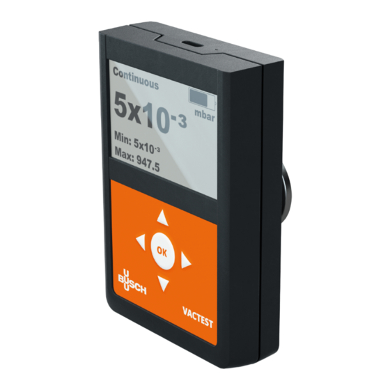
Operation | 4 Handling Press the OK-Key to switch on the device. After approx. 2 seconds the display will show the measure- ment menu with the actual pressure. To switch off the device press and hold the OK-Key for 3 sec- onds. - Page 10 4 | Operation Operating Mode In the measurement menu operating modes “Continuous“ (continuous operation) or “Auto-Off“ (au- tomatic switch-off) can be selected by means of the “Arrow Up“ key. In continuous operation the device remains powered on without limit or until an editable maximum operation time has elapsed, depending of the device configuration.
-
Page 11: Start And Stop Data Logging
Operation | 4 Start and Stop Data Logging Your VACTEST TPP 701/901 D can be operated as data logger. Multiple measurements in separate data files of type VACTEST Explorer (*.vgw) can be saved in the internal memory. Memory size will be sufficient for several million data points. -
Page 12: Graph
4 | Operation Graph The VACTEST TPP 701/901 D can plot measurements as pressure-vs-time diagram. Diagram options can be adjusted as described in section 4.6.2 Diagram-Options. [➔ 17] To start plotting measurements in a diagram select item “Graph“ from the main menu: Depending on the diagram settings pressure readings will now be plotted over time. -
Page 13: Calculation Of Leakage Rates
Operation | 4 Calculation of Leakage Rates By means of a rate-of-rise measurent the VACTEST TPP 701/901 D is able to calculate the leakage rate of a vacuum system. To start a rate-of-rise measurement select “Leakage Rate“ from the main menu: In the next step the internal volume of the vacuum vessel or system has to be entered. -
Page 14: Settings
4 | Operation Settings In order to adjust settings select item “Settings“ from the main menu. 14 | 44 Instruction Manual VACTEST TPP 701_901 D_EN_en... -
Page 15: Logging Mode
Operation | 4 4.6.1 Logging Mode Select item “Logging Mode“ in the “Settings“ menu to adjust parameters for data logger operation, i.e. logging interval and an automatic stop after a desired time limit. Logging Interval Measurement data will be stored with this adjustable time interval after the data logging is started. The edited value must finally be confirmed with the “OK“-key. - Page 16 4 | Operation CAUTION Logging interval and required logging period should match to avoid unnecessarily high data volumes! This function will terminate data logging automatically after an adjustable time limit. In the first step the function has to be enabled or disabled. To enable select “On“ and then “Arrow right“...
-
Page 17: Diagram-Options
Operation | 4 4.6.2 Diagram-Options By selecting item “Graph“ in the “Settings“ menu you can adjust parameters for the graphic display of measurements as a pressure-over-time diagram, i.e. data source, time mode and axis options. Graph Mode Under this menu item you can choose whether the pressure-over-time diagram will show all mea- surements beginning from the start of the plot (“Zoom“) or whether measurements are plotted in a rolling mode within an adjustable time frame including the current reading (“Roll“). - Page 18 4 | Operation Graph Window If a rolling mode has been selected as “Graph Mode“ this menu item will allow to set the required time frame for the diagram. The setting must finally be confirmed with the “OK“-key. Graph Axis Use this menu item to select whether the y-axis of your plot shall have linear or logarithmic scaling.
- Page 19 Operation | 4 Graph Datasource Use this menu item to select the data source for the plot, i.e. absolute or relative pressure. The set- ting must finally be confirmed with the “OK“-key. Instruction Manual VACTEST TPP 701_901 D_EN_en 19 | 44...
-
Page 20: Sensor
4 | Operation 4.6.3 Sensor Choose menu item “Settings“ / “Sensor“ to re-adjust the sensors of your VACTEST TPP 701/901 D. Further you can set parameters for gas type correction and, with combination sensors, the transi- tion mode between the sensors. Adjust This function is used to re-adjust the sensors. - Page 21 Operation | 4 NOTE To achieve optimal results of an adjustment we recommend to consider a warm-up period of at least 10 minutes at the required adjustment pressure. For adjustment at zero pressure actual pressure must be at least one decade below the lower range limit of the VACTEST TPP 701/901 D .
- Page 22 4 | Operation Gas Correction Factor The pressure reading of Pirani sensors depends on type and composition of them gas being mea- sured. The unit is adjusted for N and dry air. For other gases the pressure display can be corrected in the range below 0.5 mbar by multiplication with a related correction factor.
- Page 23 Operation | 4 Transition For devices with combination sensors use this menu item to adjust the transition mode between the two sensors: “Direct“ : Hard switch-over at an adjustable pressure “Continuous“ : Continuous transition in an adjustable pressure range “Dynamic“ : Automatic transition. Instruction Manual VACTEST TPP 701_901 D_EN_en 23 | 44...
- Page 24 4 | Operation Depending on the selected transition mode you can set the pressure range for a continuous transi- tion or the required pressure for direct switch-over under menu item “Transition Values“. Settings must finally be confirmed with the “OK“-key. 24 | 44 Instruction Manual VACTEST TPP 701_901 D_EN_en...
-
Page 25: Device Settings
Operation | 4 4.6.4 Device Settings Under menu “Settings“ / “Device“ you can change basic settings of your VACTEST TPP 701/901 D. Alarm Buzzer With this function an optic and acoustic alert function can be activated. Under “Datasource“ you can initially activate the alarm buzzer and select which measurement signal should trigger the alert. - Page 26 4 | Operation Under “Volume“ the loudness of the alert signal can be adjusted. Depending on the settings made under menu item “Switch Mode“ the alert will be triggered, as soon as an adjustable threshold is under- or overshot or if a device error has occurred: The thresholds to switch-on and switch-off the alert can be edited under menu “Switch Values“.
- Page 27 Operation | 4 All settings must finally be confirmed with the “OK“-key. Max. Operation Time This function assures that the VACTEST TPP 701/901 D will be switched-off after an adjustable maximum operation time even in operation mode “Continuous“. This will avoid unintended discharge of the bat- tery.
- Page 28 4 | Operation Clock Use these menu items for setting date format, time zone and time for the integrated real-time clock of the device: All settings must finally be confirmed with the “OK“-key. 28 | 44 Instruction Manual VACTEST TPP 701_901 D_EN_en...
- Page 29 Operation | 4 Display Instruction Manual VACTEST TPP 701_901 D_EN_en 29 | 44...
- Page 30 4 | Operation The menu is used to select menu language and display units. All settings must finally be confirmed with the “OK“-key. 30 | 44 Instruction Manual VACTEST TPP 701_901 D_EN_en...
- Page 31 Operation | 4 Interfaces This menu is used to adjust settings of the USB interface and the Bluetooth interface of the VACTEST TPP 701/901 D. Ex works the device is configured as mass storage device (“MSD Enabled“), so the stored measure- ment files will be displayed when the VACTEST TPP 701/901 D is connected to a PC.
- Page 32 4 | Operation All settings must finally be confirmed with the “OK“-key. 32 | 44 Instruction Manual VACTEST TPP 701_901 D_EN_en...
-
Page 33: Device Information
Device Information | 5 Device Information In menu “Service“ you can display information regarding device and sensor. Further it is possible to format the memory of the data logger. Device Info Instruction Manual VACTEST TPP 701_901 D_EN_en 33 | 44... - Page 34 5 | Device Information Sensor Info Under this menu item information regarding the sensor of your device is listed, for example param- eters that will help to estimate the degree of wear and tear. Displayed is a counter of operating hours as well as the number of operating hours which have elapsed since the last zero adjustment of the sensor.
-
Page 35: Vactest Explorer Software
VACTEST Explorer Software | 6 VACTEST Explorer Software VACTEST Explorer software has been especially developed for use with VACTEST gauges from Busch Vacuum Solutions and is compatible with operating system Windows. VACTEST Explorer features plotting and saving of measurement data as well as comfortable configu- ration of all device parameters. -
Page 36: Maintenance And Service
7 | Maintenance and Service Maintenance and Service DANGER Danger of possibly contaminated parts! Contaminated parts can cause personal injuries. ● Inform yourself regarding possible contamination before you start working. ● Be sure to follow the relevant instructions and take care of necessary protective measures. CAUTION The unit is not prepared for customer repair! Defective sensor heads can be exchanged on-site by calibrated replacement sensors. -
Page 37: Important Notes For Disposal
For withdrawal and free disposal of used appli- ances please contact your Busch Vacuum Solutions service or return the product with a filled-in dec- laration of contamination. Alternatively, you can dispose used appliances at officially set-up collect- ing points. -
Page 38: Technical Data
8 | Technical Data Technical Data VACTEST TPP 701 D VACTEST TPP 901 D Measurement principle piezo-resistive / heat conduction Pirani (Pirani depending on gas type) Measuring range absolute pressure: 1200 - 5.0 x 10 hPa (mbar) (900 - 5.0 x 10 Torr) relative pressure: -1060 ... - Page 39 Technical Data | 8 VACTEST TPP 701 D VACTEST TPP 901 D Vacuum connection Small flange DN 16 ISO KF Display LCD graphic display, resolution 400 x 240 Protection class IP 40 Weight 250 g Instruction Manual VACTEST TPP 701_901 D_EN_en...
-
Page 40: Eu Declaration Of Conformity
EU Declaration of Conformity The manufacturer Busch Produktions GmbH Schauinslandstr. 1 DE-79689 Maulburg declares that the gauge: VACTEST TPP 701 D; VACTEST TPP 901 D fulfill(s) all the relevant provisions from EU directives: – ‘Electromagnetic Compatibility’ (EMC) 2014/30/EU – ‘RoHS’ 2011/65/EU Restriction of the use of certain hazardous substances in electrical and electronic equipment (incl. all related applicable amend- ments) –... -
Page 41: Uk Declaration Of Conformity
UK Declaration of Conformity The manufacturer Busch Produktions GmbH Schauinslandstr. 1 DE-79689 Maulburg declares that the gauge: VACTEST TPP 701 D; VACTEST TPP 901 D fulfill(s) all the relevant provisions from UK legislations: – Electromagnetic Compatibility Regulations 2016 – Restriction of the use of certain hazardous substances in Electrical and Electronic Equipment Regulations 2012 –... - Page 42 Notes Notes 42 | 44 Instruction Manual VACTEST TPP 701_901 D_EN_en...
- Page 43 N otes Instruction Manual VACTEST TPP 701_901 D_EN_en 43 | 44...
- Page 44 With a network of over 60 companies in more than 40 countries and agencies worldwide, Busch has a global presence. In every country, highly competent local personnel delivers custom-tailored support backed by a global network of expertise. Wherever you are.
Need help?
Do you have a question about the VACTEST TPP 701 D and is the answer not in the manual?
Questions and answers