
Subscribe to Our Youtube Channel
Related Manuals for BUSCH VACTEST DTP 400 C


Summary of Contents for BUSCH VACTEST DTP 400 C
- Page 1 Instruction Manual VACTEST Vacuum Measurement Equipment Digital Transmitter DTP 400 Digital Transmitter DTP 400 C 0870205259/-0001_en / Original instructions / Modifications reserved 16/09/2021...
-
Page 2: Table Of Contents
Table of Contents Table of Contents 1 Safety ............................3 2 Product Description ........................4 2.1 Interface Illustration ......................4 2.2 Product Identification ....................... 4 2.3 Delivery Content ......................4 2.4 Proper Use ........................4 2.5 Improper Use ........................4 3 Transport and Storage.......................5 4 Installation..........................5 4.1 Installation Conditions ...................... -
Page 3: Safety
Safety | 1 Safety • Read and follow the instructions of this manual. • Inform yourself regarding hazards, which can be caused by the product or arise in your system. • Comply with all safety instructions and regulations for accident prevention. •... -
Page 4: Product Description
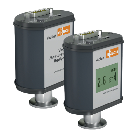
2 | Product Description Product Description The digital transmitter DTP 400 or DTP 400 C is a spiral coil filament Pirani sensor whose measurement principle is based on the thermal conductivity of gases. This sensor type provides indirect pressure measurements which are dependent on the gas nature. -
Page 5: Transport And Storage
Transport and Storage | 3 – Operation of the devices in areas with ionizing radiation. No liability or warranty will be accepted for claims arising from improper use. Transport and Storage • Check the device for transport damage. NOTICE Devices without external protection. Risk of damage to the device! •... - Page 6 4 | Installation CAUTION Overpressure in the vacuum system over 1500 mbar Damage to your health! The elastomer washers cannot withstand the pressure and can release process media. • Use sealing rings with an outer centering ring. NOTICE Dirt and damage at the vacuum flange. Impair the function of the gauge! •...
-
Page 7: Electrical Connection
Installation | 4 4.3 Electrical Connection NOTICE Establish a connection using a live cable. Risk of damage to the device! • Only connect cables when de-energised. 4.3.1 Connecting to the Active Sensor Controller For operation of the gauge with controller, a suitable measurement connection cable must be used (see accessories). -
Page 8: Connecting To The Usb/Rs485 Converter
4 | Installation 4.3.2 Connecting to the USB/RS485 Converter 24 VDC • Set the relevant address at the address selector switch, see Setting RS485 Address [► 14]. • Connect the gauge to the power supply cable. • Connect the USB/RS485 converter and secure the D-Sub connector with the screws. •... -
Page 9: I/O And Communication Port Schematic
Installation | 4 4.3.3 I/O and Communication Port Schematic The electrical connection is to be made by means of suitable cables considering EMI de- mands and according to the pin description shown below: Connector: D-Sub15, 15-pin, male Pin no. Description Pin no. -
Page 10: Change Display Unit And Orientation (Display Version Only)
5 | Operation 4.4 Change Display Unit and Orientation (Display version only) In order to change the display unit (mbar, Torr, hPa): • Hold the "Adj" pushbuton pressed while connecting power supply until the display shows "Unit". • Select the desired unit by pressing the "Adj" pushbuton. Display unit and orientation can be changed via VacTest explorer or by software com- mand, see chapter Commands Overview [► 15]. -
Page 11: Operating The Gauge
Operation | 5 5.2 Operating the Gauge The gauge is equipped with a status LED (see Interface Illustration [► 4]) signalizes the following operational states: Normal operation / Pirani (green LED flashing slowly) Error (red LED continuously on) Ready for adjustment (orange LED flashing slowly) Initializing adjustment (orange LED flashing quickly) The setpoint LEDs are on when the related relay is activated. -
Page 12: Setpoints
5 | Operation 5.3 Setpoints The gauge features 2 independent, potential-free relay contacts that can be configured via RS485 and VacTest explorer. The 2 relays are controlled by the two setpoints SP1 and SP2. Switch off Switch on Relay active Relay inactive Time 12 / 24... -
Page 13: Bake-Out
Operation | 5 5.4 Bake-out NOTICE Excessive bake-out temperature. Risk of damage to the electronics! • Baking temperatures up to 150 °C, always switch off the power supply. • Baking temperatures higher than 150 °C may damage the sensor head and electron- ics. -
Page 14: Readjustment Via Software Command
5.5.3 Readjustment via Controller See instruction manual of the controller. Communication NOTE The Busch communication protocol is available separately on request. Ask your Busch representative to get the document. 6.1 Setting RS485 Address The transmitter is equipped with a serial RS485 interface. -
Page 15: Commands Overview
Communication | 6 6.2 Commands Overview Main commands: Code Description Displays the device type. Displays the product name. Displays the device serial number . Displays the sensor head serial number. Displays the device's hardware version. Displays the device's firmware version. Displays the device's bootloader version. - Page 16 Display and set the gas correction factor for the hot cathode sensor. Display and set the gas correction factor for the cold cathode sensor. Scale the analog output characteristic of the gauge: consult the Busch com- munication protocol. 16 / 24...
-
Page 17: Setpoints
Communication | 6 6.2.1 Setpoints The gauge provides 2 independent, potential-free relay setpoints. These are available as change-over switches at the connector according to the pin assignment described in chapter I/O and Communication Port Schematic [► 9]. Relay R1, R2: The relays can be independently configured for various switching modes. The Parameter is used to query and set these switching modes. -
Page 18: Vactest Explorer Software
7 | Maintenance and Service 6.3 VacTest Explorer Software VacTest explorer software has been especially developed for use with Busch vacuum gauges and is available for Windows and Android operating systems. VacTest explorer features plotting and saving of measurement data as well as a comfort- able way of configuring all device parameters. -
Page 19: Troubleshooting
• Send unit for repair or re- ROR1" via RS485 Status LED sensor. place sensor. continuously red. Access code "7" via RS485. Error message / warning. • Contact Busch for commu- nication protocol. Instruction Manual VACTEST DTP 400_EN_en 19 / 24... -
Page 20: Spare Parts And Accessories
Software VacTest explorer - Pro version (1 license) 0870 203 191 This is only part of the available accessories, check on Busch's website or contact your Busch represen- tative for more information. 20 / 24 Instruction Manual VACTEST DTP 400_EN_en... -
Page 21: Technical Data
Technical Data | 10 10 Technical Data VacTest DTP 400 VacTest DTP 400 C Measurement principle Pirani Materials exposed to vacuum Stainless steel 1.4307, nick- Stainless steel 1.4307, nickel, el, tungsten, glass platinum / rhodium, glass Filament material Tungsten Platinum / Rhodium... -
Page 22: Gas Correction Factor
10 | Technical Data 10.1 Gas Correction Factor Correction factor for Pirani sensor: Ar ► 1.6 ► 0.89 He ► 1.0 Ne ► 1.4 CO ► 1.0 ► 0.57 ► 1.0 Kr ► 2.4 22 / 24 Instruction Manual VACTEST DTP 400_EN_en... -
Page 23: Eu Declaration Of Conformity
11 EU Declaration of Conformity This Declaration of Conformity and the CE-mark affixed to the nameplate are valid for the gauge within the Busch scope of delivery. This Declaration of Conformity is issued under the sole responsibility of the manufacturer. - Page 24 Busch Vacuum Solutions We shape vacuum for you. Argentina Denmark Malaysia South Africa info@busch.com.ar info@busch.dk busch@busch.com.my info@busch.co.za Australia Finland Mexico Spain sales@busch.com.au info@busch.fi info@busch.com.mx contacto@buschiberica.es Austria France Netherlands Sweden busch@busch.at busch@busch.fr info@busch.nl info@busch.se Bangladesh Germany New Zealand Switzerland sales@busch.com.bd info@busch.de sales@busch.co.nz...
Need help?
Do you have a question about the VACTEST DTP 400 C and is the answer not in the manual?
Questions and answers