
Related Manuals for Kohler Mira S43D


Summary of Contents for Kohler Mira S43D
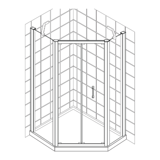
- Page 1 Leap Pentagon Enclosure (S43D) These instructions must be left with the user Installation Guide 1242344-W2-C...
- Page 2 1242344-W2-C...
-
Page 3: General Information
INTRODUCTION Thank you for purchasing a quality Mira product. To enjoy the full potential of your new product, please take time to read this guide thoroughly, having done so, keep it handy for future reference. The following pages aim to provide comprehensive installation instructions, plus advice on how to care and maintain your product. -
Page 4: Recommended Usage
Ensure the size of door/panel is suitable for the installation. Tempered safety glass cannot be cut. Ensure nothing can impact the door or glass panels during operation. When Fitting the Enclosure The wall channels must be installed onto a tiled or waterproof finished flat and even wall surface. -
Page 5: Pack Contents
PACK CONTENTS Pack 1 Pack 2 X 1 q X 1 q X 1 q X 1 q 1242344-W2-C... - Page 6 Glass Mount LH Self Adhesive Wall Mount Rubber Pad Glass Mount RH Cover Bracing Bar 1242344-W2-C...
-
Page 7: Installation
INSTALLATION 9 mm Note! Make sure that the ± 0 mm walls have been tiled down to the tray. Height of Enclosure (mm) 1900 Min/Max Frame Adjustment Enclosure Size Minimum (mm) Maximum (mm) 900 x 900 1200 x 900 1167 1197 (a) Install the shower tray in accordance with the manufacturer’s instructions. - Page 8 RH Panel Shown ± 0 mm 6 mm 9 mm (a) Position one of the panel wall channels. Using a spirit level make sure that it is upright. (b) Mark the position of the fixing holes, then remove the wall channel. (c) Drill with a 6 mm masonry bit (not supplied), and plug using the wall plugs (supplied with the door).
- Page 9 LH Panel Shown ± 0 mm 6 mm 9 mm (a) Position the second panel wall channel on the wall. Using a spirit level make sure that it is upright. (b) Mark the position of the fixing holes, then remove the wall channel. (c) Drill with a 6 mm masonry bit (not supplied), and plug using the wall plugs (supplied with the door).
- Page 10 (a) Install the side panels over the wall channels that had been secured to the wall earlier. (b) Adjust the side panels so that they are in the correct position. 1242344-W2-C...
- Page 11 Side Panel Door Panel (a) Install the door in position. (b) Push the side panel and the door frame together until the extrusions engage and lock together. 1242344-W2-C...
- Page 12 ± 0 mm (a) Centralise the door frame within the wall channels, making sure that the door frame is square. 1242344-W2-C...
- Page 13 L & R 90° (a) Using the 3.0 mm hexagonal wrench (supplied), turn through 90° clockwise in three locations to lock the door frame in position. Repeat this on the other wall channel. 1242344-W2-C...
- Page 14 Note! Ensure infill strip is installed as illustrated with thicker section towards outside of enclosure. (a) Lubricate the rubber strip with washing up liquid or a suitable lubricant to help aid installation. (b) Install the rubber strip as shown above to both sides, working from top to bottom. (c) Install the infill strip.
- Page 15 Assemble the bracing bar using the correct parts for a LH or RH enclosure. Push the glass mount and the wall mount into the end of the bracing bar and fit screws. LH Glass RH Glass Mount Mount Fixing holes should be on top of the bracing bar Wall Mount...
- Page 16 Remove the bracing bar. Make the bracing bar horizontal. Drill 2 x 6mm hole into wall. Mark the postion of the fixing holes on the wall. 5 13 5 14 Fit plugs. ±0mm Replace the bracing bar back on the glass. Fit the screws.
- Page 17 5 17 5 18 Slide the cover on to the end of the bracing bar until it locks in place. (a) Slide the cover onto the end of the (a) Fit the covers to the top of the bracing bar until it locks in place. extrusions.
- Page 18 5 20 Note! Silicone should be applied vertically where the door jamb and wall channel join on the outside of the enclosure. Note! Silicone should be applied 10cm vertically up from the base on the glass/aluminum join on the outside of the enclosure on the fixed panel. Any excess silicone should be wiped clean.
-
Page 19: Maintenance
Chrome Parts Use only cleansers expressly specified for chrome! KOHLER Glass Cleaner For occasional cleaning of glass treated with KOHLER Glass Protector or for more regular maintenance of untreated surfaces, we recommend using KOHLER Glass Cleaner. The cleaner cleans and polishes without smearing or streaking and rejuvenates the Glass Protector. -
Page 20: Spare Parts
SPARE PARTS LH Pent Panel 1781.265 Pent Panel Top Cap Pack 1781.380 Locking Mechanism Spare 1781.381 Infill Spare 1834.127 Bracing Bar Assembly 305818 Glass Cleaner 1242344-W2-C... - Page 21 RH Pent Panel 1781.265 Pent Panel Top Cap Pack 1781.380 Locking Mechanism Spare 1781.381 Infill Spare 1834.127 Bracing Bar Assembly 305818 Glass Cleaner 1242344-W2-C...
- Page 22 NOTES 1242344-W2-C...
-
Page 23: Declaration Of Performance
The performance of the products described above, are in conformity with the relevant community harmonisation legislation. This declaration of performance is issued under the sole responsibility of Kohler Mira Ltd. Signed for and on behalf of Kohler Mira Ltd. Signature:... - Page 24 United Kingdom and the Republic of Ireland). DAP 16.06.2013 5 013181 077117 Mira is a registered trade mark of Kohler Mira Limited. The company reserves the right to alter product specifi cations without notice. 1242344-W2-C © Kohler Co. January 2018...
Need help?
Do you have a question about the Mira S43D and is the answer not in the manual?
Questions and answers