Table of Contents
Advertisement
Quick Links
Advertisement
Table of Contents

Related Manuals for Luxinar MULTISCAN HE


Summary of Contents for Luxinar MULTISCAN HE
- Page 1 MULTISCAN® HE USER MANUAL laser marking system...
- Page 2 This manual is copyrighted with all rights reserved. Under copyright laws, this manual may not be copied in whole or part or reproduced in any other media without the express permission of Luxinar Ltd. Permitted copies must carry the same proprietary and copyright notices as were affixed to the original. Under law, copying includes translation into another language.
- Page 3 #409, A-dong (Bundang Suji U-Tower) 767, Sinsu-ro, Suji-gu, Yongin-si, Gyeonggi-do Republic of Korea 16827 Tel.: +82 (0)31 546 0861 www.luxinar.com/ko Luxinar Laser Technology (Shanghai) Co., Ltd (China) Room 02, 5th Floor, 8# Jiafeng Road Shanghai Pilot Free Trade Zone Shanghai, China 200131 Tel.: +86 21 6106 9917...
-
Page 5: Table Of Contents
Table of contents Preface Audience How to use this manual Admonitions Connector labels and signal names Marking and printing Safety................................1.1. General safety information......................... 1.2. Label locations.............................1 1.3. Labels..............................1.4. Maximum Permissible Exposure and Nominal Ocular Hazard Distance..........1.5. Decommissioning and disposal......................2. - Page 6 5.9. Pre-ioniser fuse replacement......................5.10. Compressed air supply........................5.11. Fume extractor..........................5.12. Product detectors..........................31 Installation..............................6.1. Unpacking and preparation.......................33 6.1.1. Delivery check..........................6.1.2. Unpacking...........................33 6.2. Mechanical Installation........................6.3. Safety guarding..........................6.4. Scanning head positioning........................ 6.5. Lens focus adjustment........................6.6. Lens protection shroud........................6.6.1.
-
Page 7: Preface Audience
Preface Audience This manual should be read by all personnel who install or operate the MULTISCAN® HE laser. Important! Read this manual carefully before operating the equipment for the first time. Pay special attention to the Safety chapter. The MULTISCAN® HE is designed and sold for integration within a marking station. The system integrator is responsible for compliance with all applicable local safety regulations. - Page 8 Preface 906-0244-00 REV 3...
-
Page 9: Safety
Luxinar Aftersales office or distributor for advice before proceeding. The installation, operation, maintenance and repair of this laser equipment must only be carried out by Luxinar service personnel or trained staff who have received correct instruction concerning the hazards associated with this particular equipment. - Page 10 Figure 2 - Main enclosure rear panel — liquid cooling Figure 3 - Main enclosure interface access panel 1. Safety 906-0244-00 REV 3...
- Page 11 Figure 4 - Main enclosure power supply Figure 5 - Main enclosure beam path covers 906-0244-00 REV 3 1. Safety...
- Page 12 Figure 6 - Laser head identification Figure 7 - Scanning head 1. Safety 906-0244-00 REV 3...
-
Page 13: Labels
1.3. Labels Figure 8 - Label 1 — Laser hazard Figure 9 - Label 2 — Class 4 laser warning 230V AC Figure 10 - Label 4 — 230V AC warning Model number Part number Serial number Input Revision Weight IP rating Figure 11 - Label 5 —... -
Page 14: Maximum Permissible Exposure And Nominal Ocular Hazard Distance
Figure 12 - Label 6 – Consult the user manual Figure 13 - Label 7 — Power supply warnings Figure 14 - Label 8 — Non-interlocked panel Figure 15 - Label 9 — Power supply identification and certification AVOID EXPOSURE INVISIBLE LASER RADIATION IS EMITTED FROM THE APERTURE Figure 16 - Laser aperture... -
Page 15: Decommissioning And Disposal
Table 2 - MULTISCAN® HE NOHD calculation Scanning head SC10 SC14 Wavelength (µm) 10.6 10.25 10.6 10.25 10.6 10.25 Lens focal length NOHD (m) (mm) — — — — — — — — — Note: Beam divergences given in the following table apply only when the marking system is operated with the complete beam delivery system attached. - Page 16 1. Safety 906-0244-00 REV 3...
-
Page 17: General Description
2. General Description 2.1. System overview The MULTISCAN® HE is a vector laser marking system comprising: • a Radio Frequency (RF) excited, diffusion cooled, CO industrial slab laser • a high-speed galvanometer scanning head • a computer-based controller to position the laser beam on the workpiece •... -
Page 18: Typical Production Line Installation
To mark characters and images, the laser beam is deflected by high-speed galvanometer mirrors controlled by a computer. The computer also switches the laser beam on and off to form individual characters. The computer is connected to a galvanometer control board via a digital interface which sends varying X and Y co-ordinate deflection values to the vector scanning head. - Page 19 The MULTISCAN® HE is intended to be used for marking materials in an industrial environment. Use of the equipment for applications other than the intended one constitutes misuse and the laser manufacturer, Luxinar Ltd does not accept liability for any damage or injury howsoever caused or arising.
-
Page 20: System Components
Position the user control panel (1) so that it is easily accessible and visible to the operator. The main enclosure (4) must be positioned so that the cooling vents have an unrestricted free flow of air to ensure adequate cooling. There must be a minimum of 0.5m clearance between the enclosure and any walls or other obstructions that could impede air flow. -
Page 21: Main Enclosure With Integrated Sr 10I Laser Head
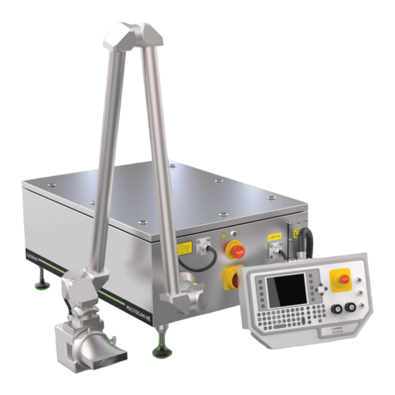
Figure 21 - MULTISCAN® HE with air/liquid cooling 2.5. Main enclosure with integrated SR 10i laser head The main enclosure contains an integrated SR 10i laser head, DC and RF power supplies, cooling system (air/liquid or liquid/liquid) and electronic control boards and interfaces for integration with the marking station. -
Page 22: Control Panel
2.8. Control panel Figure 23 - Control panel The control panel is used to programme and select the code to be marked and to control the marking process. It is connected to the main enclosure by an umbilical cable. Table 4 - Control panel features Feature Description Power on key-switch... -
Page 23: External Interface
Marking field size Final lens focal length Scanning head model (mm) (mm) 105x105 SC10 SC14 140x140 SC10 SC14 175x175 — SC10 SC14 210x210 — SC10 SC14 250x250 — — SC14 2.9.2. External interface Table 5 - External interface features Feature Description Product detector input Two independent inputs for NPN or PNP product... -
Page 24: Dimensions
2.9.3. Dimensions Table 6 - Dimensions System unit Dimensions Main enclosure — air-cooled (LxWxH) (mm) 1025x570x294 Main enclosure — liquid-cooled(LxWxH) (mm) 800x570x294 Main enclosure adjustable feet (optional) Adjustment range 85–110mm Control unit (LxWxH) (mm) 400x275.6x110 2.9.4. Weights Table 7 - Weight System unit Weight Main enclosure —... -
Page 25: Optics Purge Gas
Table 8 - Minimum laser resonator coolant temperatures Ambient temperature (°C) Relative humidity Table 9 - Coolant specification Model SR 10i Minimum flow rate (L/min) Recommended flow rate (L/min) Maximum pressure 6.0bar (88psi) Dissipation Required refrigeration capacity Coolant temperature 19–30°C (Optimum temperature 21°C. Allow 1% output power drop per 1°C increase.) Refer to document 906-0202-99 for more details. -
Page 26: Laser Characteristics
Table 11 - Environmental specifications Ambient working temperature 5–40°C (41–104°F) Storage temperature (with drained cooling circuit) 5–70°C 41–158°F) Relative humidity (non-condensing) 10–85% Maximum altitude < 2000m IP rating, all units 2.9.10. Laser characteristics The laser head is a model SR 10i sealed cavity, RF excited, diffusion cooled slab CO laser. - Page 27 SC10 SC14 Field size for 100mm focal length lens 70x70mm 70x70mm 70x70mm Field size for 150mm focal length lens 105x105mm 105x105mm 105x105mm Field size for 200mm focal length lens 140x140mm 140x140mm 140x140mm Field size for 250mm focal length lens — 175x175mm 175x175mm Field size for 300mm focal length lens...
- Page 28 2. General Description 906-0244-00 REV 3...
-
Page 29: Operation
3. Operation WARNING Risk of injury to eyes and exposed skin Use of controls or adjustments or performance of procedures other than those specified herein may result in hazardous laser radiation exposure. This is a Class 4 (Class IV) Laser and the beam is invisible to the eye. -
Page 30: Preliminary Checks
Symbol Explanation Shutter key switch: shutter closed position Shutter key switch: shutter open position Laser emission indicator Maintenance fault indicator. This fault prevents the system from marking. System standby indicator (conforms to 417-IEC-5009a). When in standby mode, the system will not mark until the operation indicated on the control panel has been performed. -
Page 31: Shut-Down
Important! Changing to different screens (status, settings, edit, etc.) incurs an additional processor load that may interrupt repetitive mark cycles. If possible, avoid changing screens during marking. 3.3. Shut-down Stop the flow of products past the detector(s). On the control panel, press F5 for Shutdown. Turn the shutter key to the Shutter closed position. -
Page 32: Restart Button
Products that trigger the detector(s) will be marked using the code displayed on the screen. • Interlock mode 1 Press the Print button. Press 'Yes' to confirm laser activation. • Interlock mode 2 This is an automatic restart mode. The system will restart and the laser will be re-enabled as soon as the interlock is reset. -
Page 33: Diagnostics And Troubleshooting
4. Diagnostics and troubleshooting 4.1. Status indicators The user interface board in the main enclosure has a set of indicator LEDs which illuminate when a fault is detected or when certain voltages are present. Table 15 - User interface board LED system status indicators Indicator number Function Interlock voltage present... - Page 34 4. Diagnostics and troubleshooting 906-0244-00 REV 3...
-
Page 35: Routine Maintenance
Every 18 months This should be carried out by a Luxinar trained engineer. Other marking system components will also require periodic inspection and cleaning. These include the compressed air supply filter, the product detectors and the fume extractor filters. The maintenance interval for these components will depend on how they are integrated into the marking station. -
Page 36: Cleaning The Final Focus Lens
Figure 26 - Key-switch covers Clean the external surfaces of the system with a mild detergent. It is advisable to use a damp cloth when cleaning the external cabinets and enclosures. Important! Take care not to allow water into the main enclosure or the final focus lens beam shroud. 5.3. -
Page 37: Interlocks
The pH value, conductivity and dissolved solids levels can be measured using a portable meter. The bacterial contamination level can be checked using a test kit. For more information and advice, contact Luxinar Aftersales. Pay particular attention to the instructions provided by the manufacturer of the NALCO water treatment kit: Drain off the contaminated cooling water. -
Page 38: Fuse Replacement
For fuse replacement specifications and details, refer to section 6.8.2. Note: If a fuse fails again when the mains supply is reconnected, this may indicate a more serious fault. For more information and advice, contact Luxinar Aftersales. 5.9. Pre-ioniser fuse replacement The MULTISCAN®... -
Page 39: Compressed Air Supply
Where the marked product materials are altered or changed after initial installation, then consult Luxinar Aftersales and the manufacturer of the fume extractor for details of any required change to the extraction filter specification. - Page 40 5. Routine maintenance 906-0244-00 REV 3...
-
Page 41: Installation
If any damage to the packaging or change to the tilt or shock labels has occurred in transit, inform both Luxinar Ltd and the shipping company before taking any other action. Insurance company inspection of the damage may be necessary before proceeding with the unpacking of the equipment. -
Page 42: Mechanical Installation
Luxinar does not accept liability for any damage or injury howsoever caused or arising. 6. Installation... -
Page 43: Safety Guarding
Before securing any item in a permanent position, it is recommended that the components are first placed in their approximate final positions to check for best orientation and location. Position the main enclosure close to the marking site on the production line. For systems with integrated laser head and the standard articulated arm, the maximum reach between the enclosure and the scanning head is approximately 1.6m. -
Page 44: Scanning Head Positioning
350mm (13.8”) between the marking point and the beam stop position. For longer separations, contact Luxinar Aftersales for advice before proceeding. The centre position of the beam stop must be positioned exactly on the centre line of the beam entry aperture. -
Page 45: Lens Protection Shroud
6.6. Lens protection shroud The lens protection shroud is used to couple a clean compressed air supply to the scanning head between the lens and the product. The compressed air creates an air curtain to prevent marking debris from contaminating the lens. Figure 29 - Lens protection shroud CAUTION Risk of optical damage in the laser head... -
Page 46: Cooling System
6.7. Cooling system 6.7.1. Internal cooling circuit — all versions Before switching on the system, the internal coolant reservoir must be filled with approved coolant. The approved coolant is Flowcool-plus mono propylene glycol, available from: ICS Cool Energy ICS House Stephenson Road Calmore Industrial Estate Totton, Southampton BD4 3SA... -
Page 47: External Cooling Circuit - Liquid-Cooled Version
6.7.2. External cooling circuit — Liquid-cooled version Figure 30 - Coolant connections Coolant drain Before transportation or storage, remove the plug and operate the coolant pump to drain all coolant from the system. Coolant in The coolant circuit includes a temperature control valve that opens when the Coolant out internal system... - Page 48 Single phase configuration 38x10mm fuse Link Figure 31 - Mains supply fuses/links Figure 32 - Power supply fuses/links Table 18 - Fuse/link configuration Fuse number Component protected Fuse rating Link FI, F2 50V power supply 3.15A (T3.15AH250V) PL1 links F1 to N F3, F4 5V/12V power supply 16A (T16AH250V)
-
Page 49: Lens Protection Air Supply
‘push in’ connector on the side of the shroud. An air purification kit meeting these requirements is available from Luxinar. This consists of a two-stage regulating filter unit. The first stage regulates the factory line pressure down to 2.4bar (20 psig) and 906-0244-00 REV 3 6. -
Page 50: Fume Extractor
These may include health and safety and environmental pollution standards. A stand-alone fume extraction system, suitable for a marking installation, is available from Luxinar. The system consists of a stand-alone fume extractor with a large-bore flexible hose and extraction nozzle designed for debris and fume removal. -
Page 51: Transport And Recommissioning
7. Transport and recommissioning 7.1. Internal cooling circuit draining — all versions Switch off the system at the mains isolator on the front panel of the main enclosure. Connect a short piece of flexible hose to the water outlet at the drain manifold. Position a suitable container to collect coolant as it drains from the system. - Page 52 7. Transport and recommissioning 906-0244-00 REV 3...
-
Page 53: Interfacing
8. Interfacing PC module Laser head Power supply Coolant reservoir User interface PCB Mains supply terminal block and fuses Figure 35 - MULTISCAN® HE main enclosure layout 906-0244-00 REV 3 8. Interfacing... -
Page 54: User Interface Pcb
8.1. User interface PCB The user interface PCB is located in the main enclosure. All control signals, monitoring outputs and interlocks are terminated on this board. Figure 36 - User interface PCB layout 8.2. Interlocks and security The MULTISCAN® HE Interlock circuits are designed to meet the requirements of EN 13849. Two sets of interlocks are provided for connection of remote guard interlocks and remote stop circuits. -
Page 55: Scanning Head To Main Enclosure Cable
Type Function External emergency stop 1, return input 24VDC interlock circuit Remote interlock 1 input 12/24VDC interlock circuit Remote interlock 1, return input 12/24VDC interlock circuit Not used Not used Interlock chain 2, J37 Emergency stop 2, volt-free output Emergency stop contact Emergency stop 2 return, volt-free output Emergency stop contact External emergency stop 2 input... -
Page 56: Product Detector
8.4. Product detector A signal indicating the presence of a product at the marking position is required to trigger product marking. The signal can be provided by: • An external product detector • A product present signal from the production line controller Where a product detector is used, it should be mounted on an adjustable bracket close to the marking position. -
Page 57: Dual Detector Installation
Figure 40 - Detector edge selection Many types of product detectors are available and must be selected for reliable operation with the product or surface to be marked. For advice about selection of product detectors, contact Luxinar Aftersales. 8.4.1. Dual detector installation The MULTISCAN®... -
Page 58: Tacho
8.5. Tacho A tacho (usually a shaft encoder) can be used to control the code length when marking on a variable speed production line. It is not required if the MULTISCAN® HE is installed on a constant speed conveyor section of the production line, where the speed past the marking position does not vary during a production run. -
Page 59: Additional Interface Connections
Refer to the Software manual for more details concerning calculation of the shaft encoder (tacho) resolution. For more information about shaft encoder options contact Luxinar Aftersales. 8.6. Additional interface connections Shutter status output J12 The Shutter status output monitors the position of the internal safety shutter. The shutter remains closed until the system is ready to print. - Page 60 Type Function 12V (protected) 12V source Open collector 100mA current drain 5–30V (external source) 12V (internal source) Open emitter 100mA current source 5–30V (external source) 12V (internal source) Common ground — Memory select input J11 The Memory select input is a 4-bit signal used to control the current code selection and/or to reset configured counter/increment fields .
- Page 61 Type Function Normally closed relay contact Volt free contact Normally open relay contact Volt free contact Common relay contact Volt free contact • System on The System on output becomes active when the main marking application is running (via the system watchdog).
- Page 62 6 DSR 7 RTS 7 RTS 8 RTS 8 RTS 9 RI 9 RI RS232 connections to RS232 connections to external device (PC, controller, etc.) interface board J7 Ethernet Contact Luxinar Aftersales for further information. 8. Interfacing 906-0244-00 REV 3...
-
Page 63: Software Configuration
9.1. Service menu Software configuration options are available on the Service menu screen. Access to this screen is only possible using the Service password. Contact Luxinar Aftersales for password details and advice. To access the screen: From the home screen, Press F9 for Menu. - Page 64 Enter the Service password and press F10 for OK. The main menu displays with Setup activated. Press F2 for Setup. The setup menu displays. Press F2 for Service. The service menu displays. • Press F1 for PC options — see section •...
-
Page 65: Pc Options
9.2. PC options Use the up/down arrows or function keys to select fields and values. Shutdown type Select the termination method for MVSEditor. Shutdown system on quit closes all operations so that the system can be switched off. Exit to Windows on quit closes MSVEditor and returns control to the operating system. -
Page 66: Print Screen Configuration
Cancel Press F5 for Cancel to discard any changes and return to the previous menu. 9.2.1. Print Screen Configuration The CTRL and ALT keys can be configured to perform various functions within the main Print screen. Disable Both keys are disabled and have no effect when pressed. Detector delay (Available in software version MVS5.50.003 and above) Press and hold CTRL/ALT keys for direct access to the Detector delay setting, without the need to fully edit the current mark code. -
Page 67: Setup I/O
Galvo scaling This field selects a scaling factor to adjust the overall mark size. Edge factor scaling This is an advanced laser setting used to prevent burn-in effects. Tube type This field selects the laser type integrated in the system. Maximum overall duty This field selects the maximum overall duty for the system. - Page 68 Maximum Buffered Triggers This field sets the maximum number of trigger signals that can be buffered before initiating a mark. Buffered Trigger Reset Mode Select the buffered trigger reset mode. Reset on pause clears any buffered trigger signals when the system enters a paused state (e.g. when an external interlock is opened).
-
Page 69: Appendix A. Coolant Requirements And Additives
<1000cfu/ml The pH value, conductivity and dissolved solids levels can be measured with a portable meter and the bacteria level can be checked with a test kit. For more information contact your local Luxinar Aftersales office. A.2. Suspended particle removal To remove particulate contamination, an in-line filter with a pore size of 100µm must be fitted as close... - Page 70 • Disposal of used material Ensure that the disposal of all the materials used in this product is conducted according to all local and national regulations. • Instructions for use Completely empty both inhibitor bottles which are included with the NALCO kit into the cooling water reservoir tank.
-
Page 71: Appendix B. Cooling System Pressure Drop Curve
Appendix B. Cooling system pressure drop curve Flow (litres/min) Figure 44 - MULTISCAN® HE pressure drop curve 906-0244-00 REV 3 B. Cooling system pressure drop curve... - Page 72 B. Cooling system pressure drop curve 906-0244-00 REV 3...
-
Page 73: Appendix C. Dimensional Drawings
Appendix C. Dimensional drawings Figure 45 - Main enclosure — liquid-cooled 906-0244-00 REV 3 C. Dimensional drawings... - Page 74 Figure 46 - Main enclosure — air-cooled C. Dimensional drawings 906-0244-00 REV 3...
- Page 75 Figure 47 - Articulated arm beam delivery — 470mm 906-0244-00 REV 3 C. Dimensional drawings...
- Page 76 Figure 48 - Articulated arm beam delivery — 640mm C. Dimensional drawings 906-0244-00 REV 3...
-
Page 77: Appendix D. Calculations For Laser Safety Glasses Selection
Appendix D. Calculations for laser safety glasses selection The Maximum Permissible Exposure (MPE) is the level of radiation to which, under normal circumstances, persons may be exposed without adverse effects. The MPE represents the maximum level to which the eye or skin can be exposed without consequential injury and is related to the wavelength of the laser radiation, the pulse duration or exposure duration, and the tissue at risk. - Page 78 Scanning head Final lens focal Beam NOHD (m) Irradiance Radiant Optical density aperture (mm) length (mm) diameter (mm) exposure 0.20 1.8x10 1.2x10 0.30 8.1x10 5.4x10 0.41 4.5x10 3.0x10 0.51 2.9x10 1.9x10 0.62 2.0x10 1.3x10 0.75 1.3x10 9.0x10 0.11 6.7x10 4.4x10 0.14 3.7x10 2.5x10...
- Page 79 Table 27 - Optical density calculation for the MULTISCAN® HE with SC7, SC10 and SC14 scanning heads — wavelength 9.3µm Scanning head Final lens focal Beam NOHD (m) Irradiance Radiant Optical density aperture (mm) length (mm) diameter (mm) exposure 0.18 1.7x10 1.1x10 0.25...
- Page 80 Visible and Invisible laser radiation and schematics contained herein are subject to change without notice. Avoid eye or skin exposure to direct or scattered radiation Luxinar Ltd Tel: +44 1482 650088 Meadow Road sales.uk@luxinar.com Bridgehead Business Park www.luxinar.com...
Need help?
Do you have a question about the MULTISCAN HE and is the answer not in the manual?
Questions and answers