
Related Manuals for Dexcowin iRayA6


Summary of Contents for Dexcowin iRayA6
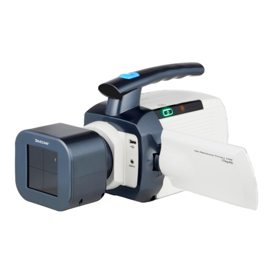
- Page 1 ADX6000s VER. 0050.4 iRayA6 (ADX6000s) User Manual More Safe / More Convenient / More Durable...
-
Page 2: Table Of Contents
Table of Contents Notice 1. General Information Introduction Symbols Used In this Manual Symbols Marked on the iRayA6 2. Warning and Instructions Precautions to Take When Using Precautions to Take When Storing Symbols and Details 3. Caution and Instructions Precautions to Take When Using and Storing Other Precautions to Take 4. - Page 3 Items to Inspect Before Requesting for Requesting for Repairs 10. Product Specification 10-1 Product Specifications and Product Warranty 10-2 Product Warranty 11. iRayA6 Technical 11-1 High Voltage Generator Documents 11-2 Electromagnetic Compatibility 11-3 Product transportation, storage conditions. and conditions of use...
-
Page 4: General Information
1. General Information Notice DEXCOWIN CO., LTD. Email: info@dexcowin.com Phone: (+82) 2 3402 5500 Fax: (+82) 2 3402 5539 Model: ADX6000S Version: 0050.4 (EN) Country: USA (EN) Initial Date: 11-06-2020 Revision Date: 29-07-2024... - Page 5 Introduction ▪ ▪...
- Page 6 Indications for Use ▪ ▪ ▪ technician. WARNING...
- Page 7 Prescription-Use Statement ▪ Contraindication ▪ This product is a medical device, and it should only be used as portable radiography device to take X-rays. This X-ray unit may be dangerous to patients and operators unless safety measures, operating instructions and maintenance schedules are observed.
- Page 8 Symbols Used in this Manual RADIATION WARNING WARNING CAUTION CHECK Symbols Used on iRayD6’s Packaging KEEP AWAY FROM RAIN FRAGILE THIS WAY UP...
- Page 9 Symbols Marked on the iRayA6 ELECTRICAL PROTECTION RADIATION WARNING WARNING CONSULT ACCOMPANYING DOCUMENTS This symbol indicates the device's model number MODEL NUMBER MANUFACTURER INFORMATION MANUFACTURE DATE SERIAL NUMBER REPRESENTATIVES The manufacturer's EU representative information is INFORMATION indicated along with this symbol.
-
Page 10: Warning And Instructions
2. Warning and Instructions Symbols and Details This sign indicates that the operator may experience physical harm or even death while operating the device. Precautions to Take When Using This X-ray unit must be operated by trained personnel in a controlled setting. - Page 11 Warnings for Battery Usage ▪ ▪ ▪ ▪ ▪ ▪ Precautions to Take When Inspecting the Product ▪ ▪ Precautions to Take When Storing Precautions to Take When Storing the Device ▪ ▪ ▪ ▪ ▪ ▪ ▪...
-
Page 12: Caution And Instructions
3. Caution and Instructions Symbols and Details CAUTION This sign indicates the possibility of incurring damage to the body if the device is used incorrectly. Precautions to Take When Using and Storing Precautions to Take When Storing the Device ▪ ▪... - Page 13 Other Precautions to Take ▪ ▪ ▪...
-
Page 14: Items To Check
4. Items to Check Symbol and Details CHECK This symbol indicates directions must be followed for product installation, operation, and maintenance. Items to Check ▪ ▪ ▪ ▪ ▪ ▪ ▪ ▪... - Page 15 Features ▪ Medical Device Name Portable X-ray System ▪ Model Name ADX6000s ▪ Product Name iRayA6 ▪ Display 4.3” Touch Panel TFT-LCD ▪ Software Self manufactured, UI and handling possible ▪ Exposure Ranges from 0.05-1.50 seconds; the time can be adjusted in 0.01 Second intervals ▪...
-
Page 16: Device
Product Specifications Product Specifications ▪ Device Main Body • Item name: Portable X-ray Radiography Device • Grade: Class Ⅱb (MDD 93/42/EEC as amended by 2007/47/EC) • Tube voltage: 50 – 80 kV (variable) • Tube current: 1 – 5 mA (variable) •... - Page 17 Battery Pack Charging Adapter ▪ Model Name: JBL7451212000302FJ ▪ Input Voltage: 100 - 240VAC, 50 - 60Hz, 1.0A ▪ Output Voltage: DC 21V ▪ Output Current: 2.0A Loading Factors Optimal Radioscopy and Radiography Settings: Utilizing the highest available x-ray tube current from the medical equipment, the specified nominal x-ray tube voltage for both radioscopy and radiography is set at 80kV and 5mA.
- Page 18 6. Product Composition Outline Product Composition ▪ ▪ ▪ ▪ ▪ ▪ ▪ ▪ ▪ ▪ ▪...
- Page 19 Main Body Battery Pack Charging Cradle Battery Charger/ Detachable Handle Wired Remote Control AC Power Cord (optional) SSD Cage/Back Scatter Storage Case User Manual/ Shield (optional) Product Warranty [Figure 6.1 Product Composition]...
- Page 20 Product Explanation Description of Main Body ▪ Radiation Field 4.3" Touch Panel Detachable Handle TFT LCD [Figure 6.2 Description of Main Body]...
- Page 21 Radiation Field Name ▪ Labels for the radiation field are displayed below. Exposure Base Line Exposure Area [Figure 6.3 Labels for the Radiation Field] GUI Screen Composition and Functions ▪ kV Display Based mA Value Based on Settings Menu Icon on Settings Set Settings Set Battery Status Icon...
-
Page 22: Power On/Off
[ Figure 7.2 Main Menu Screen] CAUTION iRayA6 has an automatic power shut off function to reduce battery consumption. The default setting is set so that the device shuts off after not having been used for five minutes and can be changed. -
Page 23: X-Ray Radiography
X-Ray Radiography Tube Voltage Settings ▪ Icon That Increases Tube Voltage in Tube Voltage Increments of 10kV Icon/Displays Current Tube Voltage Value Icon That Increases Tube Voltage in Increments of 1kV Icon That Decreases Icon That Decreases Tube Voltage in Tube Voltage in Increments of 10kV Increments of 1kV... - Page 24 Tube Current Settings ▪ ▪ Icon That Increases Tube Current in 1mA Increments Tube Current Icon Icon That Increases Tube Current in 0.1mA Increments Icon That Decreases Icon That Decreases Tube Current in Tube Current in 1mA 0.1mA Increments Increments [ Figure 7.4 Icons to Change Tube Current Value] ▪...
- Page 25 Exposure Time Settings ▪ ▪ Icon that Increases the Exposure Time in 0.1 Exposure Time Second Increments Icon/Displays Current Exposure Time Value Icon That Increases the Exposure Time in 0.01 Second Increments Icon That Decreases Icon That Decreases the the Exposure Time in Exposure Time in 0.01 0.1 Second Increments Second Increments...
- Page 26 Memory Settings [Figure 7.6 Memory Icons] Based on the selected memory setting, the values are optimized for the specific anatomical region being imaged. Users who prefer to customize these parameters can do so by utilizing the arrow keys adjacent to the "Exposure Times" icon. The following information delineates each memory icon along with its corresponding values and the anatomical region that is optimized for imaging with each respective icon.
- Page 27 X-ray Exposure ▪ [Figure 7.9 Messages That Are Displayed When Generating an X-ray] ▪ ▪ [Figure 7.10 X-ray Is Ready to be Generated]...
- Page 28 ▪ Exposure Base Line Exposure Area Display (bright part) Exposure Area Display (bright part) Subject [Figure 7.11 X-ray Exposure Field Settings] If the SSD cage is to be used, do not remove the SSD cage to bring the X-ray source closer to the patient. Do NOT make any other modifications to the device.
- Page 29 ▪ ▪ CHECK The iRayA6 emits radiation only when the EX button is pressed. Once the button is released (in the middle of irradiation), X-ray generation is suspended. ▪ [Figure 7.12 Main Menu Screen After Radiation Is Emitted]...
- Page 30 Relation between X-ray Generating Time ▪ ▪ ▪ Table 7-1 Diagnostic Reference Level ** Additional * Approximate Comparable to lifetime risk of Procedure: effective radiation natural background fatal cancer from dose: radiation for: examination: Radiography 1.5 mSv 6 months Very Low (X-ray)-Spine BONE Radiography...
- Page 31 Settings Menu Settings Menu ▪ [Figure 7.13 Settings Menu Screen] ➊ ➋ ➌ ➍...
- Page 32 Wired Remote Control Wired Remote Control Usage ▪ ▪ ▪ ▪ [Figure 7.14 Wired Remote Control Connection]...
- Page 33 Battery Inserting the Battery into the Main Body ▪ ▪ CHECK device will shut down automatically if the battery is not ▪ [Figure 7.15 Detaching the Battery Cover]...
- Page 34 ▪ [ Figure 7.16 Inserting the Battery Pack] ▪ ▪ The user should use the battery designated by the manufacturer. If the user uses a different battery, it may cause the device to malfunction.
- Page 35 Battery Level and Charging the Battery ▪ ▪ ▪ ▪ 0~10% 11~30% 31~55% 56~80% 81~100% [ Figure 7.17 Battery Level Display] ▪ ▪ ▪ ▪...
- Page 36 ▪ Adapter ※ When charging the Dexcowin's battery or [Figure 7.18 Battery Cradle and Charger Adapter] [Figure 7.19 Battery Cradle and Battery Settlings]...
- Page 37 CAUTION Use only Dexcowin's adapter and cord originally packaged with the device to prevent damage to the battery or accidents from occurring. Otherwise, the warranty will be void and the manufacturer will be exempt from any liability. The user should use the battery charger specified by the manufacturer when charging the battery.
-
Page 38: Ssd Cage
SSD Cage [Figure 7.20 SSD Cage] ▪ ▪ the iRayA6 to bring the X-ray source closer to the patient. Do NOT make any other modifications to the device. Do NOT place to bring the X-ray source closer to the patient, as this only increases the patient’s exposure to radiation. In... - Page 39 How to Assemble [Figure 7.21 How to Attach the SSD Cage]...
-
Page 40: Maintenance, Storage, And Repair
8. Maintenance, Storage, and Repair Maintenance and Storage ▪ ▪ ▪ ▪ ▪ Storage Method Check for Product Storage ▪ ▪ ▪ ▪ ▪ ▪ Charger Adapter Storage ▪ ▪ ▪... -
Page 41: Maintenance Schedule
Maintenance Schedule On-going Maintenance ▪ ▪ ▪ ▪ ▪ ▪... - Page 42 Annual User Check ▪ ▪ ▪ ▪ ▪ ▪ ▪ ▪ ▪ ▪...
- Page 43 Annual (Optional) Calibration ▪ ▪ ▪ ▪ ▪ Table 8-1. Acceptable Test Ranges Exposure Time (mSec) Test Acceptance Description Limits 50ms 100ms 300ms 1350ms...
- Page 44 Maintenance Log Sheets Year 1 Year 2 Year 3 Year 4 Year 5 Year 6 Maintenance Test Date Date Date Date Date Date /Initial /Initial /Initial /Initial /Initial /Initial...
- Page 45 Repair ▪ ▪ ▪ ▪...
-
Page 46: Items To Inspect Before Requesting For
9. Items to Inspect Before Requesting for Repairs Items to Inspect Before Requesting for Repairs SYMPTOM STEPS TO TAKE Power Defect Exposure Defect Radiation Field Defect Others... -
Page 47: Product Specifications
10. Product Specifications and Product Warranty 10-1 Product Specifications CLASSIFICATION DETAILS Product Name Grade Ⅱ Input Power Waterproof Rating Fireproof Mode of Operation Tube Voltage Tube Current Focal Point Size Voltage Consumption Voltage Usage Minimum Source to Skin Distance Cooling System Total Filtration Time Setting KV setting... -
Page 48: Product Warranty
10-2 Product Warranty ▪ ▪ ▪ ▪ ▪ ▪ ▪ ▪ S.B. Pharma GmbH... -
Page 49: High Voltage Generator
11. iRayA6 Technical Document 11-1 High Voltage Generator X-RAY Tube: D-0813B ➊ ➋ ▪ ▪ ▪ ➌ ▪ [Figure 11.1 Dimensions of the X-ray Tube]... - Page 50 ▪ ▪ ▪ ▪ [Figure 11.2 Anode Heating/Cooling Curve] ➍ ▪ ➎...
- Page 51 [Figure 11.3 Maximum Tube Current Curve by Exposure Time] ▪ Maximum Filament Current ....................3.0 A [ Figure 11.4 Emission & Filament Characteristics]...
-
Page 52: Electromagnetic Compatibility
Electromagnetic Compatibility Other cables and accessories may negatively affect EMC performance. The iRayA6 should not be used adjacent to or stacked with other equipment and if adjacent or stacked use is necessary, the iRayA6 should be observed to verify normal operation in the configuration in which it will be used. -
Page 53: Product Transportation, Storage Conditions
11-3 Product Transportation, Storage Conditions and Conditions of Use Transportation and Storage Conditions ➊ ℃ ➋ ➌ ➍ Optimal Conditions of Use ➊ ℃ ➋ ➌... -
Page 54: Labels
11-4 Labels Product Label [Figure 11.5 Product Label] High Voltage Tank (X-ray generator) Label [Figure 11.6 High Voltage Tank Label]... - Page 55 Collimator Label [Figure 11.7 Collimator Label]...
- Page 56 Charging Cradle Label [Figure 11.8 Charging Cradle Label]...
-
Page 57: Radiation Protection
Radiation Protection 11-5 WARNING This X-ray device must be operated by trained personnel in a controlled setting. -
Page 59: Sid For Proper Usage
11-6 SID for Proper Use ▪ ▪ ▪ ▪ [ Figure 11.10 Exposure Description]... -
Page 60: Leakage Radiation
Pediatric Technique Chart • • • • • Leakage Radiation 11-7 Measurement 1[m] from Focal Spot ▪ ▪... - Page 61 0˚ 270˚ 90˚ 90˚ 180˚ 0˚ 180˚ 270˚ [ Figure 11.11 Measurement Direction 1[m] from the Focal Spot]...
- Page 62 Table 11-34 Leakage Radiation 1[m] from the Focal Spot DIRECTION HORIZONTAL VERTICAL Unit: [mR/h, (mGy/h)] ND: Not Detected Measurement 1[cm] from the Case’s Surface ▪ ▪ ▪...
- Page 63 [Figure 11.12 Measurement Points 1[cm] from the Case’s Surface]...
- Page 64 Table 11-35 Leakage Radiation 1[cm] from the Case Surface TEST 1 TEST 2 TEST 3 NUMBER mR/h mGy/h mR/h mGy/h mR/h mGy/h 5.31 0.0531 5.36 0.0536 5.38 0.0538 6.03 0.0603 5.98 0.0598 5.99 0.0599 10.54 0.1054 10.57 0.1057 10.61 0.1067 11.01 0.1101 10.98...
- Page 65 200[cm] 60[cm] 60[cm] Figure 11.13 [Significant Zone of Occupancy]...
- Page 66 Test method and result of stray radiation • • • • • Figure 11.14 [Test Method of Stray Radiation] •...
- Page 67 Table 11-36 Stray Radiation 16[cm] from the Focal Spot POINT A POINT B POINT C POINT D POINT E POINT F 0 cm 20 cm 40 cm 60 cm 80 cm 100 cm 120 cm 140 cm 160 cm 180 cm 200 cm 24.000 22.000...
- Page 68 • The measurement results of stray radiation at 50cm from the focal spot are shown in Table 11-37. Table 11-37 Stray Radiation 50[cm] from the Focal Spot POINT A POINT B POINT C POINT D POINT E POINT F 0 cm 20 cm 40 cm 60 cm...
- Page 69 M o r e S a f e + M o r e C o n v e n i e n t + M o r e D u r a b l e DEXCOWIN.CO.,LTD. #901-905, 25, Gasan digital 1-ro Geumcheon-gu, Seoul, 08594 Korea...
Need help?
Do you have a question about the iRayA6 and is the answer not in the manual?
Questions and answers