Advertisement
Quick Links
Installation Guide
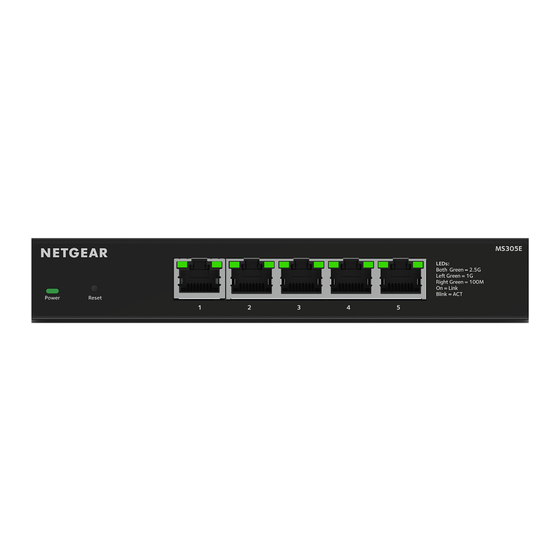
5-Port or 8-Port 2.5G Multi-Gigabit Ethernet
Plus Switch
Model MS305E
Model MS308E
Package contents
• NETGEAR 5-Port or 8-Port 2.5G Multi-Gigabit Ethernet Plus Switch
• Power adapter (varies by region)
• Wall-mount installation kit
• Rubber feet
• Installation Guide
1. Register the switch
1. From a computer or mobile device that is connected to the Internet, visit
my.netgear.com.
2. Log in to your NETGEAR account.
NOTE: If you don't have a free NETGEAR account, you can create one.
The My Products page displays.
3. From the menu on the left, select Register a Product.
4. In the Serial Number field, type the serial number of your switch.
The serial number is 13 digits long. It is printed on the switch label.
5. From the Date of Purchase menu, select the date that you purchased the
switch.
6. Click the REGISTER button.
Your switch is registered to your NETGEAR account.
A confirmation email is sent to your NETGEAR account email address.
2. Connect the switch
Computer
Laptop
NOTE: In this example, the access point (AP) requires a power adapter because
the switch does not provide PoE power.
NOTE: All switch ports support 2.5 Gbps, 1 Gbps, and 100 Mbps. You can
connect any device to any switch port. We recommend that you use Category 5e
(Cat 5e) cables or higher-rated cables for your connections.
June 2024
Sample connections
MS308E switch
Internet
Router
Smart TV
WAX610 AP
This switch is designed for indoor use only. If you want to connect it to a
device located outdoors, the outdoor device must be properly grounded
and surge protected, and you must install an Ethernet surge protector inline
between the switch and the outdoor device. Failure to do so can damage the
switch.
WARNING:
Before connecting this switch to outdoor cables or devices, see
https://kb.netgear.com/000057103 for safety and warranty information.
3. Check the LEDs
When you connect the power cord to the switch and plug it into an electrical
outlet, the LEDs indicate the status:
LED
Description
Power
The switch is powered on and operating normally.
LED
The switch is starting.
Power is not supplied to the switch.
Left
Right
Combined, these RJ-45 port LEDs indicate link, speed, and
port LED
port LED
activity.
2.5 Gbps link is established.
The port is transmitting or receiving packets at 2.5 Gbps.
1 Gbps link is established.
The port is transmitting or receiving packets at 1 Gbps.
100 Mbps link is established.
The port is transmitting or receiving packets at 100 Mbps.
No link is established.
Advertisement

Related Manuals for NETGEAR MS305E


Summary of Contents for NETGEAR MS305E
- Page 1 1. Register the switch This switch is designed for indoor use only. If you want to connect it to a device located outdoors, the outdoor device must be properly grounded and surge protected, and you must install an Ethernet surge protector inline 1. From a computer or mobile device that is connected to the Internet, visit between the switch and the outdoor device. Failure to do so can damage the my.netgear.com. switch. 2. Log in to your NETGEAR account. Installation Guide NOTE: If you don’t have a free NETGEAR account, you can create one. WARNING: Before connecting this switch to outdoor cables or devices, see The My Products page displays. https://kb.netgear.com/000057103 for safety and warranty information. 3. From the menu on the left, select Register a Product. 5-Port or 8-Port 2.5G Multi-Gigabit Ethernet 3. Check the LEDs 4. In the Serial Number field, type the serial number of your switch. Plus Switch The serial number is 13 digits long. It is printed on the switch label.
- Page 2 Applicable to 6 GHz devices only: Only use the device indoors. The operation you can insert the screws into the holes on the bottom panel. of 6 GHz devices is prohibited on oil platforms, cars, trains, boats, and aircraft, 8. From the Choose a Connection menu, select the network for this switch. except that operation of this device is permitted in large aircraft while flying NOTE: The screws are 0.25 in. (6.5 mm) in diameter, 0.63 in. (16 mm) in 9. Click the Start Searching button. length. above 10,000 feet. Operation of transmitters in the 5.925-7.125 GHz band is prohibited for control of or communications with unmanned aircraft systems. The NDT displays the IP addresses of the switches that it discovers. NOTE: The mounting holes on the switch are VESA-compliant. You can obtain a 75 mm VESA-compliant mount and mount the switch to a location 10. Click the ADMIN PAGE button. other than a wall. The login page of the device UI displays. © NETGEAR, Inc., NETGEAR and the NETGEAR, Inc. NETGEAR INTERNATIONAL LTD NETGEAR Logo are trademarks of 350 East Plumeria Drive Floor 6, Penrose Two, NETGEAR, Inc. Any non-NETGEAR San Jose, CA 95134, USA Penrose Dock, Cork, trademarks are used for reference T23 YY09, Ireland purposes only.
Need help?
Do you have a question about the MS305E and is the answer not in the manual?
Questions and answers