Table of Contents
Advertisement
Quick Links
INSTALLATION AND SERVICING
MANUAL
SOLAR 80E and 96E
Wall Mounted Combination Boiler
providing
Central Heating and Mains Fed Domestic Hot Water
Solar 80E GC Appliance No. 47 015 01
Solar 96E GC Appliance No. 47 015 02
For use with Natural Gas (G20) - Natural Gas model only
or Propane (G31) - Propane model only
EC Certificated for Safety and Performance
It is important that the boiler is installed and serviced
as described in these instructions
After installing the boiler leave these instructions with the User
Advertisement
Table of Contents

Related Manuals for ICI Caldaie SOLAR 80E


Summary of Contents for ICI Caldaie SOLAR 80E
- Page 1 Wall Mounted Combination Boiler providing Central Heating and Mains Fed Domestic Hot Water Solar 80E GC Appliance No. 47 015 01 Solar 96E GC Appliance No. 47 015 02 For use with Natural Gas (G20) - Natural Gas model only...
-
Page 2: Table Of Contents
LIST OF CONTENTS Section Subject Page Technical information......……. 3 General boiler information.....…… Boiler installation........……. 13 Fill and vent the system......…… 17 Commissioning........…….. 18 Information for the user......…… 20 Boiler servicing........…….. 20 Draining the boiler........……. 23 Replacement of components....……. 24 Wiring diagrams........………. 33 Sequence of operation charts....………... -
Page 3: Technical Information
TECHNICAL INFORMATION 1.1 TECHNICAL DATA Model Min. domestic hot water flow rate 3.0 litres/min Design domestic hot water performance 9.5 litres/min raised 35° 11.6 litres/min raised 35° C Max. mains water inlet pressure 6.0 bar Min. mains water intlet pressure 1.0 bar (remove flow restriction if <... - Page 4 23.04 78 600 2.20 28.40 96 900 34.32 117 100 11.9 3.27 PUMP PERFORMANCE Solar 80E & 96E Available Pump Head Pump Head (pump speed at setting 3) (metres water) Flow Rate (litres/h) Model Output Pump head Flow rate Btu/h...
-
Page 5: General Boiler Information
GENERAL BOILER INFORMATION BOILER DESCRIPTION The Solar 80E and 96E are room-sealed combination boilers using a small multi-directional fan-assisted balanced flue. The boilers, providing both central heating and instantaneous domestic hot water at mains pressure, have been designed for use with a sealed water central heating system. See section 2.11. - Page 6 GENERAL BOILER INFORMATION NATURAL GAS (G20) SUPPLY - Refer to section 15 for Propane (G31) The maximum natural gas requirement of the boiler is 3.27 m³/h. The meter and supply pipes must be capable of delivering this quantity of gas in addition to the demand from any other appliances in the house.
- Page 7 GENERAL BOILER INFORMATION Fig. 1 Terminal position Min. distance Directly below an opening, air brick, window, etc. 300 mm Below gutters, soil pipes or drain pipes 75 mm Below eaves 200 mm Below balconies or car port roof 200 mm From a vertical drain pipe or soil pipe 75 mm From an internal or external corner...
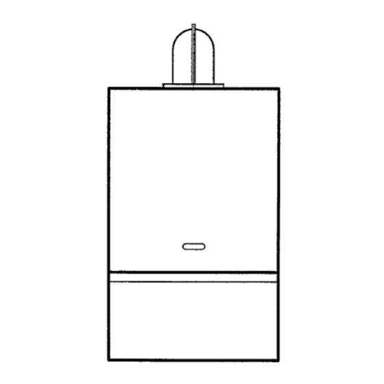
- Page 8 Take care when removing the caps as the boiler may still contain a small amount of water. Note: The descaling points at the front and rear have brass blanking caps and should not be confused with pipe connections. Fig. 2 2.10 BOILER DIMENSIONS (See Fig. 3) BOILER DIMENSION MODEL SOLAR 80E SOLAR 96E Fig. 3...
- Page 9 GENERAL BOILER INFORMATION 2.11 CENTRAL HEATING SYSTEM - SEALED SYSTEMS ONLY (See Fig. 4) The boiler is only suitable for use with a sealed system complying with the requirements of BS 5449 and 6798. The maximum temperature of the central heating water is 90 +0 - 5°C. Design notes - when designing the system, especially at the maximum output (23.3 to 28.4 kW) the pump head, expansion vessel size, radiator mean temperature, etc.
- Page 10 11 It is a condition of the manufacturers warranty that a suitable inhibitor is added to the system after the final (hot) flushing and is maintained in service. For further information concerning inhibitors contact ICI Caldaie (UK) Limited. Manual filling and make-up Fig.
- Page 11 GENERAL BOILER INFORMATION 2.13 METHOD OF OPERATION The boiler operating mode Is controlled by the ‘Heating’ switch on the control panel. When set to Hot Water Only, the boiler will only operate in the Domestic Hot Water mode. When set to Heating & Hot Water, it will operate in the Domestic Hot Water and Central Heating mode.
- Page 12 GENERAL BOILER INFORMATION The burner output is then automatically adjusted to match the system demand. As the temperature in the boiler approaches that set by the adjustable temperature selector, the burner output is automatically reduced. When the set water temperature is reached, the burner is turned off. The pump continues to run, circulating water around the system, for as long as both the timer and room thermostat (if fitted) are calling for heat.
-
Page 13: Boiler Installation
BOILER INSTALLATION UNPACK THE BOILER (See Fig. 8) Open the top of the boiler carton and remove the following loose items: 1. Boiler fittings and accessories pack Literature pack and Wall template Wall mounting template Flue restrictor Check the contents of the pack against the packing list (see section 14). - Page 14 BOILER INSTALLATION Noting the pipe positions from the labels on the boiler, secure all the valves/fittings to the boiler with the operating spindles facing forward, then connect the pipework. Use the fibre washers supplied when connecting the bent pipe connectors to the water connections on the boiler.
- Page 15 BOILER INSTALLATION 11 Position the 'O' rings (supplied in the flue accessories pack) into the recesses at each end of the inner tube of the flue elbow. Note: If the flue length is less than 1 m, fit the flue restrictor supplied into the inlet socket of the flue as shown in Fig.
- Page 16 BOILER INSTALLATION Ensure the ‘red’ rubber seals are fitted. Position the gasket (supplied with the accessories pack) over the fan spigot on top of the boiler, lining it up with the screw holes. Lubricate the rubber seals in both ends of the elbow with soap/silicon solution to aid assembly. Secure the elbow to the boiler (using the inner set of screw holes) with screws supplied in accessories pack.
-
Page 17: Fill And Vent The System
FILL AND VENT THE SYSTEM EXPANSION VESSEL PRESSURE The expansion vessel fitted Is supplied with a charge pressure of 1.0 bar (equivalent to a static head of 10.2 metres). The charge pressure must not be less than the static head at the point of connection (see Fig. 4). Do not pressurise the vessel above 1.5 bar. -
Page 18: Commissioning
COMMISSIONING Refer to Fig.14 Fig. 14 TEST FOR GAS SOUNDNESS AND PURGE THE SUPPL Y With the boiler service cock (see Fig. 14) closed (slot in operating spindle horizontal), pressure test the gas supply and inlet pipework connection to the boiler service cock for soundness in accordance with BS 6891. - Page 19 COMMISSIONING CHECK THE BURNER PRESSURES 1. With the boiler alight and operating in the central heating mode, allow it to run for 10 to 15 minutes. 2. Set the On/Off switch to Off to turn off the boiler. 3. Remove the two screws securing the top of the control panel fascia and carefully hinge it down to gain access to the burner setting pressure test point screw on the gas valve (accessible through the small hole in the rear of the control box).
-
Page 20: Information For The User
INFORMATION FOR THE USER The User must be advised (and demonstrated if necessary) of the following important points:- 1 How to light and turn off the boiler and how to operate the system controls. 2 The precautions necessary to prevent damage to the central heating system and to the building, in the event of the boiler not being used during frost conditions. - Page 21 BOILER SERVICING DISMANTLING PRIOR TO SERVICING (See Fig. 16) Open the control panel cover (hinges down). Remove the two screws at the top of the case front panel securing it to the boiler. Slide the panel up as far as possible (25 mm) and withdraw it forwards away from the boiler. Remove the eight screws securing the inner case front panel and remove the panel, take care not to damage the gasket.
- Page 22 BOILER SERVICING 5 Check the condition of the electrodes, clean with a soft brush if necessary. Replace any cracked or damaged electrodes - refer to section 9.4. Check the electrode gaps and positions (see Fig. 17) ensuring that the ignition electrode tips are:- Directly over a flame port.
-
Page 23: Draining The Boiler
DRAINING THE BOILER Refer to Figs. 14 and 19 Set the On/Off switch to Off and isolate the electricity supply. Central heating circuit Make a note of the system pressure, then dose the central heating flow and return valves. See Fig. 14. Using a suitable screwdriver, turn the operating spindles fully clockwise (34 of a turn). -
Page 24: Replacement Of Components
REPLACEMENT OF COMPONENTS It is the law that any service work must be carried out by CORGI registered personnel. Warning: Before replacing any boiler components, set the On/Off switch to Off, isolate the electricity supply and dose the boiler gas service cock (see Fig. 14). Allow the boiler to cool. Important notes when removing or replacing components: Always test for gas soundness after replacing any gas carrying components or disturbing any gas connections. - Page 25 REPLACEMENT OF COMPONENTS ELECTRODE LEAD(S) Ensure that the electricity supply has been isolated. Remove the two screws at the top of the case front panel securing it to the boiler. Slide the panel up as far as possible (25 mm) and withdraw it forwards away from the boiler. Remove the eight screws securing the inner case front panel and remove the pane!, take care not to damage the gasket.
- Page 26 REPLACEMENT OF COMPONENTS T1MER 1. Ensure that the electricity supply has been isolated. 2. Open the control panel cover (hinges down). Remove the two screws securing the control panel fascia and hinge down the fascia. 3. Remove the two screws securing the timer to the control panel fascia. 4.
- Page 27 REPLACEMENT OF COMPONENTS 9.13 MAIN DRIVER BOARD The main driver board Is positioned in the control box at the back R/H side. Ensure that the electricity supply has been isolated. Open the control panel cover (hinges down). Remove the two screws securing the control panel fascia and hinge down the fascia.
- Page 28 REPLACEMENT OF COMPONENTS 9.15.2 SET THE BURNER PRESSURES After replacing the gas valve or Modureg head, first test for gas soundness then set the burner pressures as follow: 1. Open the boiler gas service cock and test the union and inlet manifold connection to the gas valve for gas soundness.
- Page 29 REPLACEMENT OF COMPONENTS 9.17 PUMP - a replacement pump must be set at setting 3 Ensure that the electricity supply has been isolated. Dram the central heating circuit of the boiler as described in section 8. Open the control panel cover (hinges down). Remove the two screws securing the control panel fascia and hinge down the fascia.
- Page 30 REPLACEMENT OF COMPONENTS 4. Disconnect the electrical leads from the DHW sensor. 5. Unscrew the sensor and fit a replacement, using a small amount of thread sealant. Take care removing the sensor as the 3-way valve might still contain a small amount of water. Reconnect the electrical leads (polarity is not important) and re-assemble in reverse order.
- Page 31 REPLACEMENT OF COMPONENTS 9.23 AUTOMA TIC AIR VENT The automatic air vent Is positioned at the back of the boiler on the upper left hand side and Is accessible without removing the case. Ensure that the electricity supply has been isolated. Dram the central heating circuit of the boiler as described in section 8.
- Page 32 REPLACEMENT OF COMPONENTS 9.26 MAIN HEA T EXCHANGER Take care when handling the new heat exchanger not to damage the fins. Ensure that the electricity supply has been isolated. Dram the central heating circuit of the boiler as described in section 8. Remove the two screws at the top of the case front panel securing it to the boiler.
-
Page 33: Wiring Diagrams
WIRING DIAGRAMS 10.1 ILLUSTRATED WIRING DIAGRAM... - Page 34 WIRING DIAGRAMS 10.2 FUNCTIONAL FLOW WIRING DIAGRAM...
-
Page 35: Sequence Of Operation Charts
SEQUENCE OF OPERATION CHARTS 11.1 AUTOMATIC IGNITION SEQUENCE... - Page 36 SEQUENCE OF OPERATION CHARTS 11.2 OPERATION IN CENTRAL HEATING MODE...
- Page 37 SEQUENCE OF OPERATION CHARTS 11.3 OPERATION IN DOMESTIC HOT WATER MODE...
-
Page 38: Fault Finding
FAULT FINDING During the fault finding procedure the first electrical checks to be carried out are:- Short circuit, Polarity, Earth continuity and Resistance to earth. After completing a service or fault finding task which has required the breaking and remaking of electrical connections, the electrical checks must be repeated. Preliminary check of mains voltage and switches –... - Page 39 FAULT FINDING BURNER LIGHTS AND THEN GOES TO LOCK-OUT Possible cause Remedy Flame not detected Check position of electrode and adjust as necessary Check sensing lead connections, rectify as necessary Check sensing lead continuity, replace if necessary Ignition module faulty - replace Polarity of electrical supply reversed Check and rectify as necessary BURNER WILL NOT LIGHT FOR HOT WATER...
-
Page 40: Exploded Views And Parts Lists
EXPLODED VIEWS AND PARTS LISTS 13.1 CASING AND ELECTRICS P. No. 80E P. No. 96E Q.ty Description 50000553 51000554 CHASSIS 50000472 SIDE PANEL-RH 50000270 MAGNETIC CATCH 50000895 OVERHEAT THERMOSTAT 50000483 51000484 CASE UPPER FRONT PANEL 50000600 51000601 CASE LOWER FRONT PANEL 50000400 LOWER FRONT PANEL HINGE 50000063... - Page 41 EXPLODED VIEWS AND PARTS LISTS 13.2 GAS COMPONENTS P. No. 80E P. No. 96E Q.ty Description 18030310 LOCKING NUT 3/4” BSP 18022084 FLAME DETECTION ELECTRODE LEAD 50000613 GAS VALVE INLET MANIFOLD 50000630 GAS VALVE MANIFOLD GASKET (NG) 50000730 GAS VALVE NG/LPG 50000940 IGNITION CONTROL UNIT COVER 50000870...
- Page 42 EXPLODED VIEWS AND PARTS LISTS 13.3 SEALED COMBUSTION CHAMBER P. No. 80E P. No. 96E Description Q.ty 50000045 51000046 SEALED CHAMBER FRONT COVER 18010225 SEALED CHAMBER SEAL 4x6 40000960 PRESSURE SWITCH SENSING TUBE (CLEAR) 4x8 L=240 40000963 PRESSURE SWITCH SENSING TUBE (RED) 4x8 L=240 40000923 PRESSURE SWITCH COVER 50000030...
- Page 43 EXPLODED VIEWS AND PARTS LISTS 13.4 WATER COMPONENTS P. No. 80E P. No. 96E Q.ty Description 50000119 DIVERTER VALVE ASSEMBLY 40000390 PRESSURE GAUGE 18020150 AUTOMATIC AIR VENT 3/8” 18020200 SAFETY VALVE 1/2” 3 bar 18021033 PRIMARY WATER FLOW MICROSWITCH 40000410 ELBOW 50000160 CH/HW TEMPERATURE SENSOR...
- Page 44 EXPLODED VIEWS AND PARTS LISTS 13.5 HORIZONTAL FLUE (CO-AXIAL) P.No. Description FH004 Outer wall seal FH002 Concentric flue pipe 100/80 mm FHV005 Inner wall seal (optional) FHV008 Flue clamp - Elbow to pipe FHV009 Stepped flue seal - elbow to pipe FHV007 'O' ring 80 mm - inner flue seal FHV006...
-
Page 45: Packing Lists
PACKING LISTS 14.1 BOILER PACK Containing: Qty. Part No. Boiler complete with timer Installation and Servicing manual 18000050 Users Operating manual 18000060 Guarantee card 18000110 Wall mounting template 50000925 Wall mounting bracket 50000975 Flue restrictor (standard co-axial flue) 80E 50000755 Flue restrictor (standard co-axial flue) 96E 51000756 14.2... -
Page 46: Information For Propane Boilers
When replacing the main driver board set the gas jumper to position 1 and 2, see wiring diagram section 10.2. The Solar 80E and 96E burner injectors are size 75, (13 off for 80E, 15 off for 96E), part no.18011102. - Page 47 NOTE...
- Page 48 All goods sold are subject to our official Conditions of Sale, a copy of which may be obtained on application. © ICI Caldaie UK Ltd 1998. No part of this manual may be reproduced by any means without prior written consent.
Need help?
Do you have a question about the SOLAR 80E and is the answer not in the manual?
Questions and answers