Table of Contents
Advertisement
Quick Links
Advertisement
Table of Contents

Related Manuals for Level Pro Ultrapro-500


Summary of Contents for Level Pro Ultrapro-500
- Page 1 INSTRUCTION MANUAL průmyslová elektronika Ultrapro– 500 ltrasonic evel eters Before the first use of the level meter please read carefully the instructions provided in this User's Guide and keep it for future use. The manufacturer reserves the right to make changes without previous notice.
-
Page 3: Table Of Contents
TABLE OF CONTENTS 1 . Safety ............................4 2 . Packing, transportation and storage ..................4 3 . Measuring principle ........................5 4 . Range of application ........................5 5 . Features of variants ........................5 6 . Dimensional drawings ........................6 7 . I nstallation and putting into operation ..................6 8 . I nstallation instructions.......................7 9 ... -
Page 4: Safety
SEd SymBOLS In order to provide maximum safety of processes, we have defined the following safety and informa- tion instructions. Each of the instructions is marked with an icon. Alert, warning, danger This symbol informs about particularly important instructions for installation and operation of the equipment or about dangerous situations that may occur during installation and op- eration. Failure to comply with the instructions may cause failures, damage or destruction of the equipment, or may cause injuries to persons. Information This symbol informs about particularly important characteristics of the equipment. 1 . S AFETy Any operations described in this User's Guide may only be performed by trained person- nel or by an authorized person. Warranty and post-warranty repairs shall be performed exclusively on the manufacturer's site. -
Page 5: Measuring Principle
3 . m EASUriNg PriNCiPLE The UPS Series ultrasonic level sensors are compact measure-ment devices containing an electro-acoustic transducer and an electronic module. Using the electro-acoustic transducer, level meters and level sensors transmit a series of ultrasonic puls-es that spread towards the surface. The transducer then receives the reflected acoustic ... -
Page 6: Dimensional Drawings
6 . d imENSiONAL drAwiNgS UPS_–53_–01–_ UPS_–53_–02–_ UPS_–53_–06–_ UPS_–53_–20–_ UPS_–53_–10–_ ground terminal Al alloy 7 . i NSTALLATiON ANd PUTTiNg iNTO OPErATiON This procedure includes the following three steps. • NSTALLATiON • LECTriC CONNECTiON • ETTiNg... -
Page 7: I Nstallation Instructions
8 . I nstallatIon InstructIons a) The device is installed in a vertical position into the upper lid of the tank or reservoir using a lug, a fastening nut or a flange in such a way that the axis of the device is perpendicular to the surface level of the measured liquid (Fig. 1). Tightening of the level meter in the welding flange (or. by the fixing nut) is done by hand *. The device shall be installed in places with no risk of mechanical damage to the front of the sensor. b) The minimum dimensional parameters when installing into the lid or the ceiling of the tank are listed in Fig. 3. c) When installing in an open channel (sump, drain, etc.), install the device onto a console as close as possible to the expected maximum level. Fig. 1: Correct installation of the sensor, perpendicular to the liquid surface d) The reference plane for the measurement is the lower edge of the transducer (Fig.2). In compliance with the... - Page 8 the inlet neck are listed in Fig. 4. g) Foam may be produced on the surface of the meas- ured liquid during filling, mixing and other processes. The thick foam significantly absorbs the ultrasound signal and may cause malfunction of the device (Fig. 5). In those cases it is necessary to test the device in advance and, if necessary, to contact the manufacturer. h) The site for installing the level meter needs to be chosen so that the emitted acoustic signal is not affected by nearby objects (reinforcements, sup- ports, brackets, ladders, heating elements, mixers, Fig. 5: Thick foam on the surface etc.). These obstacles may result in false rebounds, x > c/12 UPS_–53–01 ;02 ;...
- Page 9 loose materials with the manufacturer. k) The measuring device shall not be installed in places with direct sunlight and shall be protected against weather conditions. If installation in places with direct sunlight is inevitable, it is necessary to mount a shielding cover above the device (Fig. 8). m) It is advisable to keep cable under the cable gland (sag- ging down) as shown in Fig. 9 to prevent penetration of moisture. Rain and condensing water can be therefore drained away freely. Fig. 8: Shielding cover against direct n) The cable gland as well as the connector shall be tightened sunlight sufficiently to prevent penetration of moisture.
-
Page 10: Electrical Connection
• If the level sensor is moun- ventilation ted to bottlenecks and places holes with barriers, or near uneven walls or the filling area, where the transmission signal could be distorted, we recommend using a guide tube (acous- tic horn). The tube must be made from a single material sleeves for ... - Page 11 BN ( ) 1 BU (3) BN ( ) 1 BK (3) Uout BU ( ) 2 BN ( ) 1 BN ( ) 1 BK (4) Uout BU (3) BU ( ) 2 BN (1) BN ( ) 1 BK (3) BU (2) BU (3)
- Page 12 BN ( ) 1 BK (3) Uout BU ( ) 2 BN ( ) 1 BN ( ) 1 BU ( ) 2 BK (4) Uout BU (3) BN ( ) 1 BN (1) BU (3) BK (3) BU (2) BN ( ) 1 BK (3) BN (1)
- Page 13 BU ( ) 2 BN ( ) 1 BU (3) BN ( ) 1 BK (3) Uout BU ( ) 2 BN ( ) 1 BK (4) Uout BU (3) BN (1) BK (3) BU (2) BN (1) BK (4) BU (3) Type UPS-500_–_ _–_–M–B(H)–_ Level meters are designed for connection to the ...
-
Page 14: Set-Up Elements
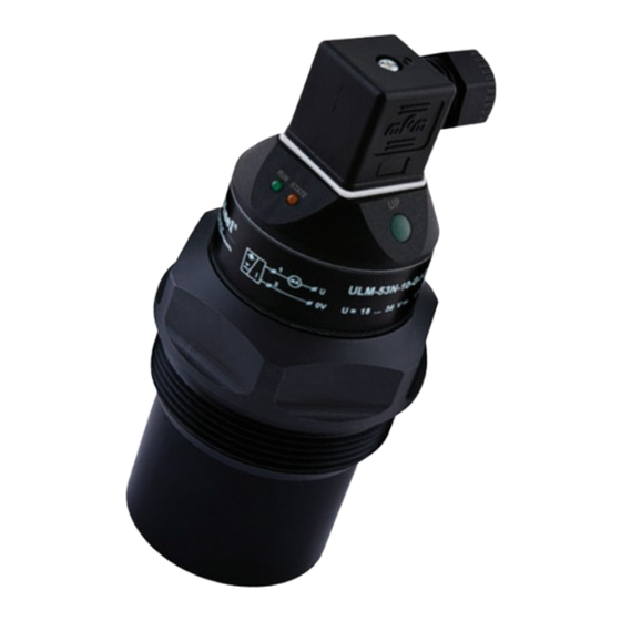
10 . S UP ELEmENTS Valid for: UPS_-53_-_ _-_-_-_-T Device type with setting using buttons DOWN button for ULM (or "OFF" for ULS) • open the setting mode connector • for ULM: direct setting of the value 4 mA (0 V) DOWN button ("OFF") • for ULS: setting limit for output disconnection UP button ("ON") • decrease of values in defined steps locking screw UP button for ULM (or "ON" for ULS) • open the setting mode LED indicator “STATE” •... -
Page 15: Status Signalization
11 . S TATUS iNdiCATiON LED indicator Colour Function short flashing (repeated depending on the measurement interval approx. 1 ... 2 s) - correct function, receipt of signal (echo) reflected from the measured surface fast flashing – the measured surface is in the dead zone of the level meter or the "RUN"... -
Page 16: Setting Procedure For Level Meters Ups-500
12 .1 . P UPS-500 rocedure manual setting level meter Connect the level meter to the supply source. Check the output value - current or voltage - using the measuring device or a connected instrument. 12.1.1. Setting using buttons (version “T”) a) Basic mode (level measurement) Setting of lower limit 4 mA (0 V) Drain the tank to the lower measured surface level. Press the DOWN button for at least 2 s to activate the setting mode (the STATE indicator LED flashes slowly). Keep the DOWN button pressed for at least additional 3 s to set the value to 4 mA (0 V) directly. In that case you can skip step 3. Press the DOWN and UP buttons to accurately set any value in individual increments (hold the relevant button to increase the adjustment step gradually). Press both buttons simultaneously for at least 1 s to confirm the set values. The STATE indica- tor LED briefly flashes three times. - Page 17 12.1.2. Setting using a magnetic pen (version “M”) a) Basic mode (level measurement) Setting of lower limit 4 mA (0 V) Drain the tank to the lower measured surface level. Set the level meter output to the value of 4 mA (0 V) by applying the magnetic pen to the EMP- TY sensitive area for at least 2 s. The STATE indicator LED flashes slowly. Hold the magnetic pen on the flat area for at least additional 3 s to confirm the set value and store it in the internal memory of the level meter. The STATE indicator LED briefly flashes three times. Any other setting is possible 2 s after the magnetic pen is removed from the sensitive area. Setting of upper limit 20 mA (10 V) Fill the tank up to the upper measured surface level. Set the level meter output to the value of 20 mA (10 V) by applying the magnetic pen to the FULL sensitive area for at least 2 s. The STATE indicator LED flashes slowly. Hold the mag- netic pen on the flat area for at least additional 3 s to confirm the set value and store it in the internal memory of the level meter. The STATE indicator LED briefly flashes three times. Any other setting is possible 2 s after the magnetic pen is removed from the sensitive area. Factory default settings Disconnect the level meter from supply voltage (e.g. by disconnecting the connector).
- Page 18 12 .2 . P UPS-500 rocedure manual setting sensor The UPS-700 sensor can work in two modes: a) Mode O (closed output when the maximum level is exceeded) - the sensor output is closed when the level rises to the upper set point and open when the level drops to the lower set point b) Mode C (open output when the maximum level is exceeded) - the sensor output is open when the level rises to the upper set point and closed when the level drops to the lower set point Connect ...
- Page 19 12.2.2. Setting using a magnetic pen (version “M”) a) Mode O (closed output when the maximum level is exceeded) Setting of disconnected output Drain the tank to the lower measured surface level. Open the sensor output by placing the magnetic pen to the OFF sensitive area for at least 2 s. The STATE indicator LED flashes slowly. Hold the magnetic pen on the OFF flat area for at least additional 3 s to confirm the set value and store it in the internal memory of the level meter. The STATE indicator LED briefly flashes three times. Any other setting is possible 2 s after the magnetic pen is removed from the sensitive area. Setting of connected output Fill the tank up to the upper measured surface level. Closed the sensor output by placing the magnetic pen to the ON sensitive area for at least 2 s. The STATE indicator LED flashes quickly. Hold the magnetic pen on the ON flat area for at least additional 3 s to confirm the set value and store it in the internal memory of the level meter. The STATE indicator LED briefly flashes three times. Any other setting is possible 2 s after the magnetic pen is removed from the sensitive area. Factory default settings Disconnect the sensor from supply voltage (e.g. by disconnecting the connector).
Need help?
Do you have a question about the Ultrapro-500 and is the answer not in the manual?
Questions and answers