Chapters
Table of Contents

Related Manuals for Beko HIAW 64225 SX


Summary of Contents for Beko HIAW 64225 SX
- Page 1 Built-in Hob / User Manual Einbau-Kochfeld / Bedienungsanleitung Table de cuisson encastrable / Manuel d’utilisation HIAW 64225 SX 185910381_1/ EN/ DE/ FR/ R.AI/ 11.06.24 17:37 7751688343...
- Page 2 Welcome! Dear Customer, Thank you for choosing the Beko product. We want your product, manufactured with high quality and technology, to offer you the best efficiency. Therefore, carefully read this manual and any other documentation provided before using the product.
-
Page 3: Table Of Contents
Cleaning the hob ......31 Table of Contents Cleaning the Control Panel.... 32 1 Safety Instructions......9 Troubleshooting ......32 Intended Use........Child, Vulnerable Person and Pet Safety ..........Electrical Safety......Safety While Working with Gas..Transportation Safety ....Installation Safety......Safety of Use ......... -
Page 4: Safety Instructions
1 Safety Instructions • This section includes the Intended Use safety instructions necessary • This product is designed to be to prevent the risk of personal used at home. It is not suitable injury or material damage. for commercial use. •... -
Page 5: Electrical Safety
• This product should not be 2. Cut off the power cable and used by people with limited disconnect it with the plug physical, sensory or mental ca- from the product. pacity (including children), un- 3. Take precautions to prevent less they are kept under super- children from entering the vision or receive the necessary... - Page 6 • Plug the product into an outlet • Portable power sources or that meets the voltage and fre- multiple plugs may overheat quency values specified on the and catch fire. Keep multiple type label. plugs and portable power • (If your product does not have sources away from the a mains cable) only use the product.
-
Page 7: Safety While Working With Gas
Safety While Work- tion, carbon monoxide (CO) might develop. Carbon monox- ing with Gas ide is a colourless, odourless • CAUTION: The use of gas and very toxic gas, which has a cooking products causes the lethal effect even in very small formation of substances re- doses. -
Page 8: Transportation Safety
• Request information about gas ial or thick cardboard and tape emergency telephone numbers it tightly. Secure the moving and safety measures in case parts of the product firmly to of gas smell from you local prevent damage. gas provider. •... -
Page 9: Safety Of Use
• Do not install the product near does not get caught when the a window. There is a risk that moving parts move (eg the hob flame will ignite cur- drawer). In addition, the gas tains and flammable materials hose should not be placed in around the hob. -
Page 10: Temperature Warnings
• Never use the product when • CAUTION: In solid or liquid oil your judgement or coordina- cooking, it is dangerous to tion is impaired by the use of leave the hob unattended, alcohol and/or drugs. which may cause a fire. NEVER •... -
Page 11: Environmental Instructions
2 Environmental Instructions 2.1 Waste Directive 2.2 Package Information Packaging materials of the product are 2.1.1 Compliance with the WEEE Dir- manufactured from recyclable materials in ective and Disposing of the accordance with our National Environment Waste Product Regulations. Do not dispose of the pack- This product complies with EU WEEE Dir- aging waste with the household or other ective (2012/19/EU). -
Page 12: Product Introduction
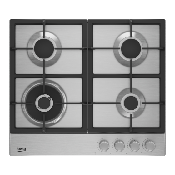
3.1 Product introduction 1 Normal burner 2 Auxiliary burner 3 Hob control knobs 4 Wok burner 5 Normal burner 3.2 Product Accessories There are various accessories in your product. Depending on the product model, the supplied accessory varies. All accessor- ies described in the user’s manual may not be available in your product. -
Page 13: Technical Specifications
3.3 Technical Specifications General Specifications of Hob Product external dimensions (height/width/depth) (mm) 46 / 580 / 510 Hob installation dimensions (width / depth) (mm) 560 / 480-490 Voltage/Frequency 220-240 V ~ 50 Hz Cable type and section used/suitable for use in the min. - Page 14 Values stated on the product labels or in the documentation accompanying it are obtained in laboratory conditions in accordance with relevant standards. Depend- ing on operational and environmental conditions of the product, these values may vary. Country gas categories/types/pressure You can find the gas type, pressure and gas category that can be used for the country where the product will be installed in the table below.
- Page 15 COUNTRY CATEGORY GAS TYPE AND PRESSURE CODES Cat II 2H3B/P G20,20 mbar G30,30 mbar Cat II 2H3B/P G20,20 mbar G30,30 mbar Cat II 2H3B/P G20,20 mbar G30,30 mbar Cat II 2H3B/P G20,20 mbar G30,30 mbar Cat II 2H3B/P G20,20 mbar G30,30 mbar Cat II 2H3B/P...
-
Page 16: Installation
4 Installation 4.1 Right place for installation General warnings • The hob is designed for installation into • Refer to the nearest Authorised Service commercially available work tops. A Agent for installation of the product. safety distance must be left between the Make sure that the electric and gas in- appliance and the kitchen walls and fur- stallations are in place before calling the... - Page 17 Minimum distance between the cut-out and the Minimum distance between the rear edge of the side wall. cut-out and the rear wall. Hob Control Type Burner Plate Type Hob Width# (mm) X (mm) Y (mm) Side knob control Metal 580 / 610 Side knob control Glass 590 / 600 / 601 / 641 / 646...
-
Page 18: Electrical Connection
4.2 Electrical connection 10-11,5 11,5-13 General warnings 13-15,5 • Disconnect the product from the electric 15,5-17 connection before starting any work on 17-19 1000 the electrical installation. There is an 19-24 1250 electric shock hazard. Rooms that do not have openable doors •... -
Page 19: Gas Connection
ted through fixed electrical installation Risks of fire: directly without using plug and socket • If you do not make the connection ac- outlet/line. cording to the instructions below, there will be the risk of gas leakage and fire. If your appliance has a cord and plug: Our company cannot be held responsible Perform the electrical connection of your for damages resulting from this. - Page 20 3. You must check for leakage of the con- nection part after connection. EN 10226 R1/2” type connection 1. Place the new seal in the connection Gas outlet connection piece : piece and make sure the seal is seated correctly. 2.
- Page 21 • Gas appliances and systems must be Leakage check at the connection point regularly checked for proper functioning. • Make sure that all knobs on the product Regulator, hose and its clamp must be are turned off. Make sure that the gas checked regularly and replaced within the supply is open.
- Page 22 with integrated sealing joint. When repla- Check if the rubber sealing washer is cing or moving the cooker, the standard re- properly seated in the union of the quires that the flexible connector is re- elastomer flexible connector. placed by a new flexible connecter of the Hand tighten the elastomer flexible new generation.
- Page 23 Cylindrical thread Fixed connection BGV-APPROVED Gas appliance Gas appliance G 1/2 taps G 1/2 cylindrical according according to NBN 115 to NBN 115 Fixed connection of the flexible connector The connection may not be made with a angle piece coupling with cylindrical thread as used in the past in flexible connections (see case A).
-
Page 24: Installing The Product
4.4 Installing the product Rear view (connection holes) Location of the connection holes shown in 1. Remove burners, burner caps and grills the below figure are schematic,may vary on the hob from the product. depending on the product model. Fix them 2. -
Page 25: Gas Conversion
4.5 Gas Conversion General warnings • Before starting any work on the gas in- stallation, disconnect the gas main sup- ply. There is the risk of explosion! • All gas injectors must be replaced and the burning adjustment of the gas taps must be made in reduced flow rate posi- tion in order to make the product suitable for use with another gas. - Page 26 Unless there is an abnormal condi- tion, do not attempt to remove the gas burner taps. You must call an Authorised service agent or techni- cian with licence if it is necessary Exchange of injector for the burners to change the taps. 1.
-
Page 27: First Use
connection the soapy water will begin to froth. In this case, tighten the in- jector with a reasonable force and re- peat step 3 process once again. Flow rate adjustment screw Leakage check at the injectors If the froth still persist you must turn Before carrying out the conversion on the off the gas apply to the product imme- product, ensure all control knobs are turned... -
Page 28: How To Use The Hob
NOTICE: During the first use, smoke and odour may come up for several hours. This is normal and you just need good ventila- tion to remove it. Avoid directly inhaling the smoke and odours that form. 6 How to use the hob 6.1 General information on hob usage •... -
Page 29: Operation Of The Hobs
6.2 Operation of the hobs 6. Adjust your desired power level. Turning off the gas burners Gas burner control knob Bring the burner knob to off position (top). If the flames of the burner are extin- guished inadvertently, turn off the burner control knob. -
Page 30: General Information About Baking
7 General Information About Baking You can find tips on preparing and cooking catches fire, cover it with a fire blanket or your food in this section. damp cloth. Turn off the hob if it is safe to do so and call the fire department. 7.1 General warnings about cooking •... -
Page 31: Cleaning Accessories
• Stainless-inox surface may change col- Plastic parts and painted surfaces our in time. This is normal. After each op- • Clean plastic parts and painted surfaces eration, clean with a detergent suitable using dishwashing detergent, warm wa- for the stainless or inox surface. ter and a soft cloth or sponge and dry •... - Page 32 7. You may use the Quick&Shine cleaning 2. Place the burner head ensuring that it agents for the oven interiors and grills, passes through the burner spark plug used on enamelled surfaces and recom- (4). Turn the burner head right and left mended by the authorized service, espe- to make sure that it is seated in the cially for persistent stains on enamelled...
- Page 33 Arcelik A.S. Karaağaç Caddesi No:2-6 Sütlüce, 34445, Turkey Made in TURKEY Importer in Russia: «BEKO LLC» Address: Selskaya street, 49, Fedorovskoe village, Pershinskoe rural settlement, Kirzhach district, Vladimir region, Russian Federation 601021 The manufacture date is included in the serial number of a product specified on rating label, which is located on a product, namely: first two figures of serial number indicate the year of manufacture, and last two –...
- Page 34 Wilkommen! Sehr geehrter Kunde, sehr geehrte Kundin, Vielen Dank, dass Sie sich für das Beko Produkt entschieden haben. Wir stellen Ihnen die- ses Produkt vor, das mit hoher Qualität und Technologie hergestellt wurde, um Ihnen die beste Effizienz zu bieten. Lesen Sie dieses Handbuch und alle anderen mitgelieferten Do- kumentationen sorgfältig durch, bevor Sie das Produkt verwenden.
- Page 35 Allgemeine Reinigungshinweise ... 64 Inhaltsverzeichnis Reinigung des Zubehörs....66 1 Sicherheitshinweise ....... 36 Reinigung des Kochfelds....66 Verwendungszweck ...... 36 Bedienfeld reinigen ......67 Besondere Sicherheitshinweise 9 Fehlerbehebung ......67 rund um Kinder, schutzbedürftige Menschen und Haustiere....Sicherheitshinweise zu Elektroge- räten ..........
-
Page 36: Sicherheitshinweise
1 Sicherheitshinweise • Dieser Abschnitt enthält die Si- • Nehmen Sie keine technischen cherheitshinweise, die erfor- Veränderungen am Produkt derlich sind, um die Gefahr von vor. Personen- oder Sachschäden Verwendungszweck zu vermeiden. • Bei Weitergabe des Produkts • Dieses Produkt wurde für die an eine andere Person zum Verwendung zu Hause entwi- persönlichen Gebrauch oder... -
Page 37: Sicherheitshinweise Zu Elektrogeräten
über die möglichen Gefahren • Drehen Sie den Griff der Töpfe des Gerätes und einen siche- und Pfannen zur Seite der The- ren Umgang damit aufgeklärt ke, damit Kinder nicht greifen wurden. Dies gilt natürlich und verbrennen können. auch für sämtliche sonstigen •... - Page 38 den Angaben auf dem Typen- • Klemmen Sie das Netzkabel schild des Gerätes passt. Las- nicht unter oder hinter das Ge- sen Sie die Erdung von einem rät. Stellen Sie keine schweren qualifizierten Elektriker erledi- Gegenstände auf dem Netzka- gen. Benutzen Sie das Gerät bel ab.
-
Page 39: Safety While Working With Gas
geraten. Halten Sie Mehrfach- • Ziehen Sie den Stecker aus der steckdosen und tragbare Steckdose, indem Sie das Ge- Stromquellen vom Gerät fern. häuse des Steckers und nicht • Falls das Netzkabel beschä- das Kabel selbst benutzen. digt wird, muss es vom Her- Safety While Wor- steller, dem autorisierten Kun- king with Gas... - Page 40 verfügt. Stellen Sie sicher, dass ler empfohlenen Zeiträume der Kohlenmonoxidsensor ord- oder bei Bedarf ausgetauscht nungsgemäß funktioniert, und werden. warten Sie den Sensor regel- • Reinigen Sie die Gaskochzo- mäßig. Der Kohlenmonoxid- nen regelmäßig. Achten Sie sensor sollte nicht weiter als 2 darauf, dass das Gas nach Meter vom Produkt entfernt dem Reinigen sauber ver-...
-
Page 41: Sicherheit Beim Transport
• Schalten Sie alle Ventile an • Überprüfen Sie das Produkt vor Gaskochgeräten und am Gas- der Installation auf eventuelle zähler am Hauptsteuerventil Transportschäden. Wenden ab, es sei denn, es befindet Sie sich bei Schäden an den sich in einem geschlossenen Importeur oder das autorisierte Raum oder Keller. - Page 42 • Halten Sie die Umgebung aller • Der Anschluss des Gerätes an Lüftungskanäle des Produkts die Gasversorgung darf nur offen. von qualifizierten Fachkräften • Stellen Sie das Produkt nicht in vorgenommen werden. Falls der Nähe eines Fensters auf. Installations- oder Reparaturtä- Es besteht die Gefahr, dass die tigkeiten von Laien ausgeführt Flamme des Kochfeldes Vor-...
-
Page 43: Sicher Bedienen
Warnhinweise zu Sicher bedienen hohen Temperaturen • Stellen Sie sicher, dass das • WARNUNG: Wenn das Produkt Produkt nach jedem Gebrauch in Gebrauch ist, werden das ausgeschaltet ist. Produkt und die zugänglichen • Wenn Sie das Gerät über einen Teile heiß. Es ist darauf zu ach- längeren Zeitraum nicht benut- ten, das Produkt und die Heiz- zen, ziehen Sie den Netzste-... -
Page 44: Sicherheitshinweise Zum Reinigen Und Pflegen
Stromversorgung, ersticken 1.10 Sicherheitshinweise Sie die Flammen mit einem zum Reinigen und Feuerlöschlappen, einer Pflegen schwer entflammbaren Decke • Warten Sie, bis das Produkt ab- oder dergleichen. gekühlt ist, bevor Sie es reini- • Seien Sie vorsichtig, wenn Sie gen. Heiße Oberflächen verur- alkoholische Getränke in Ihren sachen Verbrennungen! Gerichten verwenden. -
Page 45: Tipps Zum Energiesparen
2.3 Tipps zum Energiesparen • Benutzen Sie Töpfe und Pfannen, deren Größe und Deckel für die Kochzone ge- Gemäß EU 66/2014 sind die Informationen eignet sind. Wählen Sie immer die richti- zur Energieeffizienz auf der mit dem Pro- ge Kochgeschirrgröße für Ihre Speisen. dukt gelieferten Quittung zu finden. -
Page 46: Technische Spezifikationen
3.3 Technische Spezifikationen Allgemeine Informationen zum Herd Produkt-Außenabmessungen (Höhe/Breite/Tiefe) (mm) 46 /580 /510 Einbaumaße des Kochfeldes (Breite / Tiefe) (mm) 560 / 480-490 Spannung / Frequenz 220-240 V ~ 50 Hz Verwendeter/geeigneter Kabeltyp und -querschnitt geeig- min. H05V2V2-FG 3 x 0,75 mm2 net für die Verwendung im Produkt Gesamter Gasverbrauch (kW) 7,8 (567 g/h - G30) - Page 47 Die auf den Produktetiketten oder in der Begleitdokumentation angegebenen Werte werden unter Laborbedingungen in Übereinstimmung mit den einschlägigen Nor- men ermittelt. Je nach Betriebs- und Umgebungsbedingungen des Produkts kön- nen diese Werte variieren. Länder-Gaskategorien/-typen/-Druck In der nachstehenden Tabelle finden Sie die Gasart, den Druck und die Gaskategorie, die in dem Land, in dem das Produkt installiert wird, verwendet werden können.
- Page 48 LÄNDER CO- KATEGORIE GASART UND -DRUCK Cat II 2H3B/P G20,20 mbar G30,30 mbar Cat II 2H3B/P G20,20 mbar G30,30 mbar Cat II 2H3B/P G20,20 mbar G30,30 mbar Cat II 2H3B/P G20,20 mbar G30,30 mbar Cat II 2H3B/P G20,20 mbar G30,30 mbar Cat II 2H3B/P G20,20 mbar...
-
Page 49: Installation
4 Installation • Überprüfen Sie das Gerät vor der Installa- Allgemeine Warnungen tion auf etwaige Schäden. Lassen Sie es • Wenden Sie sich für die Installation des nicht installieren, wenn das Gerät beschä- Produkts an den nächstgelegenen autori- digt ist. Beschädigte Produkte stellen ein sierten Servicepartner. - Page 50 Mindestabstand zwischen dem Ausschnitt und Mindestabstand zwischen der Hinterkante des der Seitenwand. Ausschnitts und der Rückwand. Steuerungstyp des Koch- Brennerplattentyp Kochfeldbreite# (mm) X (mm) Y (mm) felds Seitenknopfsteuerung Metall 580 / 610 Seitenknopfsteuerung Glas 590 / 600 / 601 / 641 / 646 580 / 585 / 590 / 600 / 601 / Vorderknopfsteuerung Metall / Glas...
-
Page 51: Elektrische Verbindung
Installieren Sie dieses Gerät nicht in einem Raum unter der Erdoberfläche, es sei denn, es ist auf mindestens einer Seite zur Erd- oberfläche hin offen. 8-10 10-11,5 4.2 Elektrische Verbindung 11,5-13 13-15,5 Allgemeine Warnungen 15,5-17 • Trennen Sie das Produkt vom Stroman- 17-19 1000 schluss, bevor Sie mit Arbeiten an der... -
Page 52: Gasanschluss
wenden Sie für den Stromanschluss kei- • Der Hersteller haftet nicht für Schäden, ne Verlängerungs- oder Mehrfachsteck- die durch Eingriffe entstehen, die von un- dosen. befugten/nicht lizenzierten/unqualifizier- • und müssen die entsprechende Steckdo- ten Personen oder Technikern durchge- se/Leitung und den entsprechenden Ste- führt wurden. - Page 53 • Für den Gasanschluss und die Umstel- • Stellen Sie sicher, dass das Erdgasventil lung muss ein Schraubenschlüssel ver- leicht zugänglich ist. wendet werden. • Schließen Sie Ihr Produkt mit einem fle- • Für den Gasanschluss muss ein Schrau- xiblen Gasschlauch, der den örtlichen benschlüssel verwendet werden.
- Page 54 • Beim Herstellen des Gasanschlusses muss eine neue Dichtung verwendet wer- den. • Der Gasanschluss muss über einen Gas- schlauch oder einen Festanschluss erfol- gen. Anschluss mit geklemmtem (gewindelo- 3. Setzen Sie die neue Dichtung in den Si- sem) Gasschlauch cherheitsgasschlauch/-rohr ein.
- Page 55 Dichtheitsprüfung an der Verbindungsstel- dürfen nur Verbindungsstücke aus geprüf- tem Elastomermaterial verwendet werden, diese sind mit „AGB/BGV“ gekennzeichnet. • Stellen Sie sicher, dass alle Knöpfe am Verbindungsstücke in zwei unterschiedli- Produkt ausgeschaltet sind. Stellen Sie chen Ausführungen sicher, dass die Gaszufuhr geöffnet ist. Bereiten Sie Seifenschaum vor und tra- Die Verbindungsstücke der älteren Genera- gen Sie ihn auf den Anschlusspunkt des...
- Page 56 Das Verbingdungsstück besteht aus einem elastischen Schlauch und zwei mechanischen Anschlusstutzen, einer mit Überwurfmutter und der andere mit fester Mutter. Verbindungsstück AGB/BGV Verbindungsstück Übergangsstück Überwurfmutter Verbindungsstück AGB/BGV Free nut Für den Zusammenbau muss der fixe Anschluss un bedingt als erstes am Eingang den Gaskochers angeschraubt werden, nachdem man dort je nach Geometrie des Anschlussstutzens die geeigneten Dichtmaterialien angebracht bzw.
-
Page 57: Geräte Installieren
Konisches Gewinde Zylindrisches Gewinde Vorhandenes nach ISO 7-1 nach ISO 228-1 Gewinde am Gaskocher? Befestigung des Übergangsstücks am Gaskocher (ISO 7-1 Innengewinde, konisch und Außengewinde, zylindrisch). Die Verbindung wird mit einem Dichtungsprodukt abgedichtet. Befestigung des Verbindungsstücks auf der Seite des Gaskochers und auf der Seite des Absperrhahns mit einem Außengewinde. - Page 58 5. Zentrieren Sie das Produkt auf der Ar- Das Kochfeld enthält Komponen- beitsplatte. ten, die mit Gas und Strom arbeiten. Aus diesem Grund darf das Koch- 6. Fixieren Sie das Kochfeld durch die Aus- feld nur durch die Befestigungslö- sparungen im Unterteil hindurch mit den cher unter ausschließlichem Ein- Montageklemmen.
-
Page 59: Gasumwandlung
umwandeln können. Sie können in dieser Tabelle nicht in nicht spezifizierte Gasar- ten umrechnen. • Ein für die Gasart, die Sie umwandeln möchten, geeigneter Ersatzinjektor ist min. 15 mm möglicherweise nicht im Lieferumfang des Produkts enthalten. Sie erhalten die Endkontrolle Injektoren beim autorisierten Service 1. - Page 60 Reduzierte Gasdurchflusseinstellung für Kochfeldhähne 1. Zünden Sie den Brenner an, der einge- stellt werden soll, und drehen Sie den Knopf auf die reduzierte Position. 2. Entfernen Sie den Knopf vom Gashahn. 5. Wenn Ihr Produkt über eine Wok-Brenn- 3. Verwenden Sie einen Schraubendreher kammer mit seitlichem Injektor verfügt, geeigneter Größe, um die Einstellschrau- entfernen Sie den Injektor mit einem...
-
Page 61: Erste Verwendung
schluss Gas austritt, beginnt das Sei- fenwasser zu schäumen. Ziehen Sie in diesem Fall den Injektor mit angemes- sener Kraft fest und wiederholen Sie Schritt 3 noch einmal. Einstellschraube für die Durchflussmenge Dichtheitsprüfung an den Einspritzdüsen Bevor Sie den Umbau am Produkt durch- Wenn der Schaum immer noch anhält, führen, stellen Sie sicher, dass alle Bedien- müssen Sie die Gaszufuhr zum Produkt... -
Page 62: Bedienung Kochfeld
2. Wischen Sie die Außenflächen des Gerä- HINWEIS: Bei der ersten Anwendung kann tes mit einem feuchten Tuch oder es über mehrere Stunden zu Rauch- und Schwamm ab, trocknen Sie mit einem Geruchsentwicklung kommen. Dies ist nor- trockenen Tuch nach. mal, und Sie brauchen nur eine gute Belüf- tung, um diese zu entfernen. -
Page 63: Bedienung Der Kochfelder
Verwenden Sie keine Töpfe/Pfannen, die 3. Mit dem entstehenden Funken wird das die oben angegebenen Abmessungen über- Gas entzündet. schreiten. Die Verwendung größerer Pfan- 4. Halten Sie nach der Erstzündung den nen/Töpfe als angegeben kann zu einer Knopf 3-5 Sekunden lang gedrückt. Kohlenmonoxidvergiftung und Überhitzung 5. -
Page 64: Allgemeine Reinigungshinweise
tiefe und flache Bratpfanne aus Blech, in Lassen Sie den Knopf los, wenn der der gehacktes Gemüse und Fleisch in kurz- Brenner nicht innerhalb von 15 Se- er Zeit auf starker Flamme gegart wird. kunden gezündet wird. Warten Sie Da die Speisen in solchen Pfannen, die die mindestens 1 Minute, bevor Sie es Hitze schnell und gleichmäßig leiten, in kur- erneut versuchen. - Page 65 Kratzbürsten, Draht, Schwämme, Reini- • Reinigen Sie sie mit einem weichen gungstücher mit Schmutz- und Wasch- Schwammtuch und einem flüssigen mittelrückständen). (nicht kratzenden) Reinigungsmittel, das • Bei der Reinigung nach jedem Gebrauch für Edelstahl-Oberflächen geeignet ist, wird kein spezielles Reinigungsmaterial und wischen Sie sie in eine Richtung ab.
-
Page 66: Reinigung Des Zubehörs
• Verfärbungen und Flecken auf den Glas- 5. Reinigen Sie die Brennerkappen und flächen treten im Laufe der Zeit unwei- -köpfe nach jedem Vorgang mit Reini- gerlich auf, dies ist völlig normal. gungswasser und trocknen Sie sie an- schließend ab. Kunststoff- und lackierte Teile •... -
Page 67: Bedienfeld Reinigen
Brennerkopf Brennerkammer Zündkerze (bei Modellen mit Zündung) 8.4 Bedienfeld reinigen • Wischen Sie die Panele und die Knöpfe mit einem feuchten, weichen Tuch ab und trocknen Sie sie mit einem trockenen Tuch. Entfernen Sie nicht die darunter lie- genden Knöpfe und Dichtungen, umdas Bedienfeld zu reinigen. - Page 68 • Das Gerät darf nicht an eine (geerdete) Steckdose angeschlossen werden. >>> Prüfen Sie, ob das Gerät an der Steckdo- se angeschlossen ist. • (Falls Ihr Gerät über eine Zeitschaltuhr verfügt) Die Tasten auf dem Bedienfeld funktionieren nicht. >>> Wenn Ihr Produkt über eine Tastensperre verfügt, ist die Tastensperre möglicherweise aktiviert, deaktivieren Sie die Tastensperre.
- Page 70 Bienvenue ! Cher client, chère cliente Nous vous remercions d’avoir choisi l’appareil Beko. Nous voulons que votre appareil de haute qualité et doté d’une technologie de pointe vous offre une efficacité optimale. Pour ce faire, lisez attentivement ce manuel et tout autre document fourni avant d’utiliser l’appa- reil.
- Page 71 7 Informations générales sur la cui- Table des matières sine..........1 Consignes de sécurité....72 Avertissements généraux sur la Utilisation prévue......72 cuisson avec la table de cuisson.. Sécurité des enfants, des per- 8 Entretien et nettoyage....100 sonnes vulnérables et des ani- Consignes de nettoyage géné- maux domestiques......
-
Page 72: Consignes De Sécurité
1 Consignes de sécurité • Cette section contient les ins- • N’apportez pas de modifica- tructions de sécurité néces- tions techniques à l’appareil. saires à la prévention des Utilisation prévue risques de dommage corporel ou de dommage matériel. • Cet appareil est conçu pour •... -
Page 73: Sécurité Électrique
connaissances, à condition • AVERTISSEMENT : pendant qu’ils soient encadrés ou for- l’utilisation, les surfaces acces- més à l’utilisation sécuritaire et sibles de l’appareil sont aux dangers de l’appareil. chaudes. Tenez les enfants à • Les enfants ne doivent pas l’écart de l’appareil. jouer avec l’appareil. - Page 74 • La fiche ou les raccords élec- • Assurez-vous de ne pas coin- triques de l’appareil doivent cer le câble d’alimentation lors être facilement accessibles. Si de la mise en place de l’appa- cela est impossible, il doit y reil après le montage ou le net- avoir un mécanisme (fusible, toyage.
-
Page 75: Sécurité Lors Du Travail Avec Du Gaz
• Ne branchez jamais la fiche de teur mécanique). Une utilisa- l’appareil dans une prise cas- tion intensive du produit pen- sée, détachée ou démontée. dant une longue période peut Assurez-vous que la fiche est nécessiter une ventilation sup- entièrement insérée dans la plémentaire : par exemple, l'ou- prise. - Page 76 le gaz brûle bien si les • Demandez des informations flammes sont continues et sur les numéros de téléphone bleues. Si les flammes sont d'urgence de gaz et les me- ondulées, coupées et intensé- sures de sécurité en cas ment jaunes, le gaz ne brûle d'odeur de gaz à...
-
Page 77: Sécurité Des Transports
Sécurité des trans- • Avant d'installer l'appareil, véri- fiez s’il présente des dom- ports mages. Ne faites pas installer • Avant de transporter l’appareil, l'appareil si celui-ci est endom- débranchez-le du secteur et magé. déconnectez les raccorde- • Évitez d'utiliser des matériaux ments de gaz. -
Page 78: Sécurité D'utilisation
• Il ne doit pas y avoir de tuyau reil et des ustensiles de cuis- de gaz, de tuyau d'eau en plas- son de l’appareil. L’endomma- tique ou de prise sur le mur ar- gement du tuyau à gaz peut rière ou latéral de l'endroit où... -
Page 79: Alertes De Température
ments est altéré par la Consignes de sécu- consommation d’alcool et/ou rité relatives à la cuis- de drogues. • Les objets inflammables ne • AVERTISSEMENT : Veuillez doivent pas être conservés à respecter le processus de cuis- l'intérieur et autour de la zone son. -
Page 80: Sécurité Relative À L'entretien Et Au Nettoyage
1.10 Sécurité relative à • Ne lavez jamais l’appareil par pulvérisation ou aspersion l’entretien et au net- d’eau ! Il existe un risque toyage d’électrocution ! • Attendez que l’appareil refroi- • N’utilisez pas de nettoyeur va- disse avant de le nettoyer. Les peur pour nettoyer l’appareil, surfaces chaudes peuvent cau- car il peut provoquer un choc... -
Page 81: Votre Appareil
3 Votre appareil Dans cette section, vous trouverez une vue d'ensemble du produit. Les images et cer- taines caractéristiques peuvent varier selon le type d’appareil. 3.1 Présentation de l’appareil 1 Brûleur normal 2 Brûleur auxiliaire 3 Boutons de commande de la plaque 4 Brûleur wok de cuisson 5 Brûleur normal... -
Page 82: Spécifications Techniques
3.3 Spécifications techniques Caractéristiques générales de Hob Dimension externe de l’appareil (hauteur/largeur/profon- 46 / 580 / 510 deur)(mm) Dimensions d'installation de la table de cuisson (largeur / 560 / 480-490 profondeur) (mm) Tension/fréquence 220-240 V ~ 50 Hz Type et section du câble utilisé / adapté à l’utilisation min. - Page 83 Les valeurs indiquées sur les étiquettes de l’appareil ou dans la documentation ac- compagnant l’appareil sont obtenues dans des conditions de laboratoire, en conformité avec les normes applicables. Ces valeurs peuvent varier en fonction des conditions d’utilisation et l’environnement de l’appareil. Catégories/types/pressions de gaz par pays Vous trouverez dans le tableau ci-dessous le type de gaz, la pression et la catégorie de gaz qui peuvent être utilisés dans le pays où...
- Page 84 CODES PAYS CATÉGORIE TYPE DE GAZ ET PRESSION Cat II 2H3B/P G20,20 mbar G30.30 mbar Cat II 2H3B/P G20,20 mbar G30.30 mbar Cat II 2H3B/P G20,20 mbar G30.30 mbar Cat II 2H3B/P G20,20 mbar G30.30 mbar Cat II 2H3B/P G20,20 mbar G30.30 mbar Cat II 2H3B/P...
-
Page 85: Installation
4 Installation 4.1 Avant l'installation Avertissements généraux • Cette table de cuisson est destinée à être • Adressez-vous à l'agent de service agréé installée sur un plan de travail en vente le plus proche pour l'installation du pro- dans le commerce. Une distance de sé- duit. - Page 86 Distance minimale entre la découpe et la paroi la- Distance minimale entre le bord arrière de la dé- térale. coupe et la paroi arrière. Type de contrôle de la Type de plaque de Largeur de la plaque de cuis- X (mm) Y (mm) plaque de cuisson brûleur...
-
Page 87: Connexion Électrique
ture de ventilation fixe peut comprendre tels que les tapis et autres revêtements de des ouvertures pour les briques Airbriques sol, etc., n'affectent pas le dégagement existantes, la dimension de l'ouverture de la lorsque la porte est fermée. gaine de la hotte d'extraction etc La cuisinière peut être située dans une cui- sine, une cuisine/salle à... -
Page 88: Raccordement Au Gaz
• Les données d'alimentation secteur • Le produit ne peut être connecté au sys- doivent correspondre aux données spéci- tème d'alimentation en gaz que par une fiées sur l'étiquette de type du produit. personne ou un technicien autorisé/licen- L'étiquette de type se trouve à l'arrière du cié/qualifié. - Page 89 par exemple). En outre, il ne doit pas être doit y avoir une vanne de gaz naturel à la placé dans des espaces où il pourrait sortie du système de gaz à raccorder au être pressé. produit. • Ne déplacez pas le produit dont le raccor- •...
- Page 90 • Le raccordement au gaz doit être effec- tué via un tuyau de gaz ou un raccord fixe. Raccord avec flexible de gaz serré (sans fi- letage) 1. Placez le nouveau joint dans la pièce de raccordement pour gaz liquide et assu- 3.
- Page 91 rez de la mousse savonneuse et appli- Deux générations de flexibles en élasto- quez-la sur le point de raccordement du mère tuyau pour contrôler les fuites de gaz. L’ancienne génération de flexibles en élas- • Une partie savonneuse moussera en cas tomère est équipé...
- Page 92 Le flexible se compose d’un tuyau souple et de deuxx raccords mécaniques. L’un des raccords est avec écrou libre et l’autre avec raccord fixe. Tuyauterie flexible AGB/BGV Tuyauterie flexible Ecrcu libre Pièce de transition Tuyauterie flexible AGB/BGV Free nut Pour le montage, il est indispensable de visser en premier lieu le raccord fixe du flexible sur l’entrée de l’appareil à gaz après y avoir monté...
-
Page 93: Installation Des Produits
Filet conique suivant Filet cylindrique suivant Type de filet la norme ISO 7-1 sur I’appareil à gaz ? la norme ISO 228-1 Monter la pièce de transition (filetage conique intérieure ISO 7-1 vers filetage cylindrique extérieure) sur I’appareil. L’étanchéité dans le filet est obtenue au moyen d’un prodult d’étanchéité. Monter la flexible du cóté... - Page 94 6. Utiliser des colliers d'installation fixe la La hotte comporte des éléments plaque en ajustant les orifices sur l'em- fonctionnant à l’électricité et au placement inférieur. gaz. À cet effet, il convient de la fixer au plan de travail uniquement par les orifices de fixation, en utili- sant seulement les éléments et vis de fixation fournis, et en suivant les...
-
Page 95: Conversion De Gaz
tir dans votre région. Vous ne pouvez pas convertir en types de gaz non spécifiés dans cette table. • L'injecteur de rechange adapté au type de gaz que vous souhaitez convertir peut ne min. 15 mm pas être fourni avec le produit. Vous pou- vez vous procurer les injecteurs auprès Vérification finale du service agréé... - Page 96 2. Retirez le bouton du robinet de gaz. 3. Utiliser un tournevis de taille appropriée pour régler la vis de réglage du débit. 4. Pour le GPL (butane - propane), tourner la vis dans le sens horaire. Pour le gaz naturel, vous devez tourner la vis dans le sens inverse des aiguilles d'une montre 5.
-
Page 97: Première Utilisation
Contrôle de fuite au niveau des injecteurs Avant d'effectuer la conversion sur le pro- duit, assurez-vous que tous les boutons de commande sont en position arrêt. Après la conversion correcte des injecteurs, pour chaque injecteur doit être vérifié la fuite de gaz. -
Page 98: Utilisation De La Table De Cuisson
6 Utilisation de la table de cuisson 6.1 Informations générales sur l’utili- ture de sortir des casseroles/poêles et vous n’aurez pas besoin de les nettoyer sation de la table de cuisson inutilement. Avertissements généraux • Ne placez pas les couvercles des casse- •... -
Page 99: Fonctionnement Des Plaques De Cuisson
6.2 Fonctionnement des plaques de Relâchez le bouton si le brûleur cuisson n’est pas allumé au bout de 15 se- condes. Attendez au moins 1 mi- Bouton de commande de brûleur à gaz nute avant de réessayer. Il y a risque d’accumulation de gaz et d’explosion ! 6. -
Page 100: Informations Générales Sur La Cuisine
Brûleur wok mément, la valeur nutritive des aliments est préservée et les légumes restent crous- Les brûleurs wok vous aident à cuisiner tillants. plus rapidement. Le wok, qui est particuliè- Vous pouvez également utiliser le brûleur rement utilisé dans la cuisine asiatique, est wok pour les casseroles ordinaires. - Page 101 • Aucun produit de nettoyage spécial n'est • La surface en acier inoxydable ou en inox nécessaire lors du nettoyage effectué peut changer de couleur avec le temps. après chaque utilisation. Nettoyez l'appa- C’est normal. Après chaque opération, reil à l'aide d'un détergent pour lave-vais- nettoyez avec un détergent adapté...
-
Page 102: Accessoires De Nettoyage
qu’il agisse correctement. Nettoyez en- Veillez à ce que la bougie d’allumage et suite la surface en verre à l’aide d’un chif- l’élément thermique soient complète- fon humide. ment secs. • Les décolorations et les taches sur la sur- 5. Après chaque opération, nettoyez les face en verre sont normales et ne pré- couvercles et les têtes de brûleurs avec sentent pas de défauts. -
Page 103: Nettoyage Du Bandeau De Com- Mande
Tête de brûleur Chambre de combustion Bougie d’allumage (dans les modèles avec al- lumage) 8.4 Nettoyage du bandeau de com- mande • Lors du nettoyage du bandeau de com- mande, essuyez celui-ci à l’aide d’un chif- fon doux humide et séchez-les à l’aide d’un chiffon sec. - Page 104 • (Si votre appareil est équipé d’une minu- terie) Les touches du panneau de com- mande ne fonctionnent pas. >>> Si le ca- denas est allumé, désactiver la sécurité comme indiqué au chapitre : Activation du verrouillage de touches. Il n'y a pas d'étincelle d'allumage. •...
Need help?
Do you have a question about the HIAW 64225 SX and is the answer not in the manual?
Questions and answers