Table of Contents
Advertisement
Quick Links
Advertisement
Table of Contents

Subscribe to Our Youtube Channel
Related Manuals for Fisher-Price Power Wheels Eliminator 73180


Summary of Contents for Fisher-Price Power Wheels Eliminator 73180
- Page 1 This Owner's Manual is provided and hosted by Appliance Factory Parts. FISHER PRICE 73180 Owner's Manual Shop genuine replacement parts for FISHER PRICE 73180 Find Your FISHER PRICE Ride On Parts - Select From 999 Models -------- Manual continues below --------...
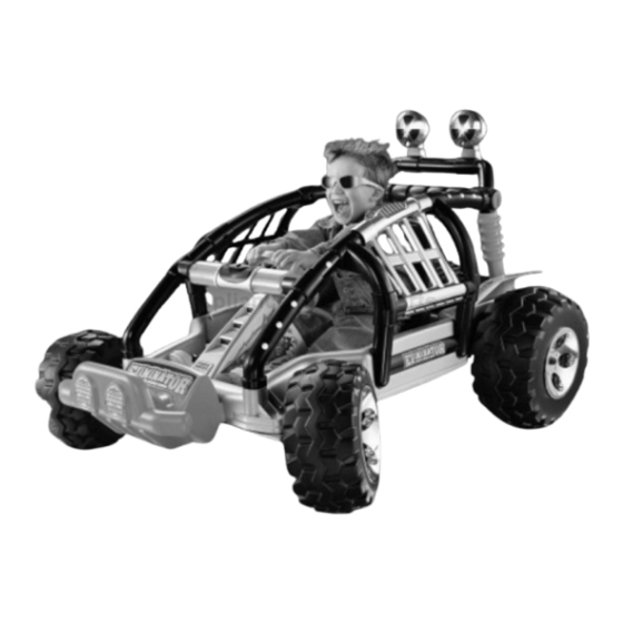
- Page 2 Product features may vary from the picture above. Owner’s Manual with Assembly Instructions Please read this manual and save it with your original sales receipt. For Model 73180 Tools needed for assembly: Phillips Screwdriver, Hammer, Pliers, and Safety Scissors (not included). Use only with a Power Wheels ®...
-
Page 3: Table Of Contents
Table of Contents Important Information ..............2 Warnings and Cautions . -
Page 4: Warnings And Cautions
Warnings and Cautions ELECTRICAL HAZARD WARNING • Battery can fall out and injure a child if vehicle tips over. Always use battery clamp. • PREVENT FIRE - Never modify the electrical system. Alterations could cause a fire resulting in serious injury and could also ruin the electrical system. -
Page 5: Parts
Parts • If you experience a problem with this product, or are missing a part, please call us at 1-800-348-0751, rather than return this product to the store. • Please identify all parts before assembly and save all packaging material until assembly is complete to ensure that no parts are discarded. - Page 6 Parts Roll Cage - Right Side Roll Cage - Left Side Door Handle ™ Light Cover - 2 Door Hinge Shock Set - 2 (Left and Right) Door Sound Bar Battery Clamp Light Rack Steering Wheel Collar Steering Wheel Cap Brush Guard Steering Column Steering Wheel...
- Page 7 Parts Radio Knob - 3 Key Assembly 12 Volt Battery 12 Volt Charger Hex Bushing - 6 Not Shown: Label Sheet - 2 #8 x " Screw - 24* #8 x " Screw - 2 #8 x 1 " Screw - 4 "...
-
Page 8: Parts Diagram
Parts Diagram Note: Some parts shown are assembled Steering Column/Brush Guard Assembly on both sides of the vehicle. Door Hinge Steering Linkage Bar Vehicle Body Door Handle Front Axle - 2 Steering Column Sound Bar .354 (Small Diameter) Cap Nut Front Wheel - 2 Light Rack Rear Axle... -
Page 9: Battery Charging
Battery Charging ELECTRICAL HAZARD WARNING CAUTION • Battery can fall out and injure a child Use the charger in dry locations only. if vehicle tips over. Always use battery clamp. About Thermal Fuses • PREVENT FIRE Your Power Wheels ® 12 volt battery is equipped with a - Never modify the electrical system. -
Page 10: Assembly
Assembly Battery Charging WARNING Battery Children can be harmed by small parts, sharp edges and sharp points in the vehi- cle’s unassembled state, or by electrical items. Care should be taken in unpacking and assembly of the vehicle. Children should not handle parts, including the bat- tery, or help in assembly of the vehicle. - Page 11 Assembly Door Assembly Right Fender Left Roll Cage Connector Post Cross Support Left Fender • Position the left roll cage with the connector post facing up. • Using safety scissors, separate the right and left fen- • Fit the cupped end of the door against the cross support ders from the plastic connector.
- Page 12 Assembly Door Left Roll Cage Right Roll Cage Door Hinge • Place the right roll cage on a flat surface with the inside facing up. • Insert two #8 x " screws through the holes in the door hinge and into the door. •...
- Page 13 Assembly Light Rack Light Rack Assembly Right Roll Cage Left Roll Cage Left Inner Shock Half Button Front View • Insert two #8 x " screws into the inner half of the shock set. • Tighten the screws with a Phillips screwdriver. Do not Sound Bar over-tighten.
- Page 14 Assembly Roll Cage Assembly Light Rack Assembly Sound Bar Vehicle Body Motors • Insert four #8 x " screws through the roll cage and into the light rack assembly and sound bar. IMPORTANT! • Tighten the screws with a Phillips screwdriver. - The front axles have been placed in the motors for Do not over-tighten.
- Page 15 Assembly Rear Axle .437 Cap Nut • Insert four #8 x " screws through the vehicle body and into the roll cage assembly, as shown. • Tighten the screws with a Phillips screwdriver. Do not • Position a .437 cap nut on a flat surface and fit one end over-tighten.
- Page 16 Assembly Driver Rear (Large) Wheel Bushing Rear Driver Ribs Driver Driver Rear Barrel Side Motor Axle Hubcap Gearbox Teeth .437 Cap Nut Hex Bushing Hint: You may want the help of another adult to complete rear axle assembly steps 19 - 21. •...
- Page 17 Assembly Barrel Ring Side Side Steering Large Large Washer Washer Hex Bushing Pivot Pivot Short Short Steering Linkage Front Axle Front Axle Front Axle Bushing Large Washer • Position the steering linkage with the pivots on the Hubcap bottom of the steering linkage. Make sure the pivots are positioned exactly as shown above.
- Page 18 Assembly Light Covers Light Rack Brush Guard • Align the tabs on the insides of the KC ™ light covers with the notches on the light rack housings and snap the light covers to the housings. • Hold the brush guard in place and position the vehicle body upright.
- Page 19 Assembly Brushguard Hole Square Opening Lock Nut #8 x " screws Steering Linkage Assembly Lock Nut Steering Column Bottom View • Holding the brush guard and bolts in place, carefully Bottom View position the vehicle body on its side. • Hand-tighten a lock nut on the end of each bolt. •...
- Page 20 Assembly .354 Cap Nut Steering Steering Wheel Wheel Cap Steering Wheel Collar Steering Column • Fit the steering wheel cap into the center of the steering wheel. • Insert two #8 x " screws into the steering wheel cap. “UP” •...
- Page 21 Assembly 12 Volt Battery Battery Clamp Looped Arms Battery Compartment Slots • Once the battery is charged, it is ready to be installed in Slots your vehicle. • Place the battery between the motors. Make sure that the motor harness connector is not under the battery. Battery Square Slot Clamp...
- Page 22 Assembly • Seat your child in the vehicle to check foot to pedal dis- tance to make sure the seat is positioned correctly for your child. • Once the seat is correctly positioned, insert two #8 x “ screws through the holes in the seat and into the vehicle body.
- Page 23 Assembly 1.5V x 3 “AA” (LR6) SHOWN ACTUAL SIZE Rear Battery Press Compartment Here Rear Slot Sound Bar Slot Decorative Battery Engine Compartment Door • Press down to fit the tabs on the rear of the decorative engine into the slots in the back of the vehicle body. Note: To disassemble the decorative engine and access •...
-
Page 24: Label Decoration
Label Decoration Proper label application will help to keep the labels looking their best! When applying labels, keep the following guidelines in mind: • Wash your hands before applying the labels. • Before applying the labels, wipe the surface of the vehicle with a clean, dry cloth to remove any dust or oils. •... -
Page 25: Battery Care And Disposal
Battery Care and Disposal Disposal Care If a battery leak develops, avoid contact with the leaking • Your Power Wheels ® battery is a sealed lead-acid acid and place the damaged battery in a plastic bag. See battery. It must be recycled or disposed of in an environ- information below for proper disposal. -
Page 26: Rules For Safe Driving
Rules for Safe Driving RIDING HAZARD WARNING Prevent Injuries and Deaths • Direct Adult Supervision Required • Keep Children Within Safe Riding Areas These areas must be: - away from swimming pools and other bodies of water to prevent drownings - generally level to prevent tipovers Use vehicle on generally level ground ONLY! - away from steps, driveways, roads... -
Page 27: How To Operate Your Vehicle
How to Operate Your Vehicle Beginner Use - Low Speed Drive To Back Up As assembled, your vehicle is ready to roll in low speed mph, maximum). It has been pre-set so it will only operate in low speed. After your child has mastered the basic skills of driving and understands the rules for safe driving, it’s time to disconnect the high speed lock-out to allow the vehicle to operate in low or high speed. -
Page 28: Caring For Your Vehicle
How to Operate Your Vehicle Caring For Your Vehicle Advanced Use - High Speed Drive • Check all screws and cap nuts, and their protective cov- erings regularly and tighten as required. Check plastic parts on a regular basis for cracks or broken pieces. •... -
Page 29: Problems And Solutions Guide
Problems and Solutions Guide IMPORTANT! If you experience a problem with your vehicle, first check the Problems and Solutions Guide below. If you still experience a problem, please contact Power Wheels ® Consumer Relations, toll-free at 1-800-348-0751 between 8 AM and 6 PM (EST) Monday through Friday. Or, contact your local Power Wheels authorized service center. - Page 30 Problems and Solutions Guide Problem Possible Cause Solution Vehicle was running but Loose wire or loose connectors Check all wires and connectors. Make sure the motor suddenly stopped harness connector is plugged into the battery, and that there are no loose wires around the motors. Tripped thermal fuse Each Power Wheels ®...
- Page 31 Problems and Solutions Guide Problem Possible Cause Solution Vehicle runs sluggishly Undercharged battery Charge the battery. A new battery should have been charged for at least 18 hours before using the vehicle for the first time. After first-time use, recharge the battery for at least 14 hours after each use.
- Page 32 Problems and Solutions Guide Problem Possible Cause Solution When the foot pedal is pressed, Loose wire or connector Check all wires around the motors and all connectors the vehicle won’t run without to make sure they are tight. a push “Dead Spot”...
-
Page 33: M Statement Of Limited Warranty
Bumper-to-Bumper* Limited Warranty *One year limited warranty from the date of purchase on the Power Wheels vehicle. ® Six month limited warranty on the 12 volt battery. For the original purchaser, this one year limited warranty covers the Power Wheels ride-on vehicle (purchased from ®... - Page 34 Authorized Service Centers DELAWARE TIFTON - Western Auto, 354 South Main Street, 31794, KANSAS (912) 382-5767 SELBYVILLE - Ahern & Son, Inc., #2 S. Dupont Hwy Rt. 2, COLBY - Gavon’s Electronics, 1870 South Range, 67701, VALDOSTA - Harry B. Anderson, Inc. Western Auto, 19975, (302) 436-4100 (785) 462-6601 31601, (912) 242-5945...
- Page 35 Authorized Service Centers MICHIGAN MONTANA SEA CLIFF - Shabra Electronics, 400 Glen Cove Avenue, 11579, (516) 671-2218 ALMONT - Almont Do It Center #421, 4545 Van Dyke, BILLINGS - Radio Equipment Company, 1205 Monad STATEN ISLAND - Springstead Lumber, 4255 Amboy 48003, (810) 798-8922 Rd., 59101, (406) 256-9778, (800) 711-4024 Road, 10308, (718) 984-0300...
- Page 36 Authorized Service Centers OKLAHOMA DARLINGTON - Hobbies and More, 1570 South Main UTAH Street, 29532, (843) 393-0355 MC ALESTER - Quality Upholstery, 803 E. Gene Stipe OREM - The Mending Shed, 1735 South State Street, EASLEY - Trails End Bicycles, 110 Pendleton Street, Blvd., 74501, (918) 423-4747 84058, (801) 225-8012, (800) 339-9297 29640, (864) 306-1684...
- Page 37 Authorized Service Center list in this manual. ® Fisher-Price and Power Wheels by Fisher-Price are U.S. trademarks of Mattel, Inc. Fisher-Price, Inc., a subsidiary of Mattel, Inc., East Aurora, New York 14052 U.S.A. ©2000 Mattel, Inc. All Rights Reserved. Printed in the U.S.A.
Need help?
Do you have a question about the Power Wheels Eliminator 73180 and is the answer not in the manual?
Questions and answers