LockMasters LOCKONE LKM10K Installation Instructions Manual
Exit only panic bar model
Hide thumbs
Also See for LOCKONE LKM10K:
- Operating instructions (2 pages) ,
- Installation instructions manual (16 pages)

Subscribe to Our Youtube Channel
Related Manuals for LockMasters LOCKONE LKM10K


Summary of Contents for LockMasters LOCKONE LKM10K
- Page 1 2nd Generation FF-L-2890B Lock Type III & IV EXIT ONLY Panic Bar Model Installation Instructions In A Single Motion, We’ll Change The Way You Think About Security. Model: EXIT ONLY Panic Device...
-
Page 2: Important Safety Notes
LKM10K EXIT ONLY Panic Device Installation The LKM10K is the second generation of pedestrian door lock devices produced by Lockmasters IMPORTANT SAFETY NOTES Inc. It was designed from the ground up to meet the needs to secure Sensitive Compartmented Information Facilities while combining Panic Hardware. - Page 3 Limited Liability Product Warranty Information Lockmasters, Inc. warrants to the original retail purchaser for a period of two (2) year from the purchase date of the product that the product shall be free of defects in the materials and workmanship, provided there is compliance with all installation, operating and maintenance instructions provided by Lockmasters, Inc.
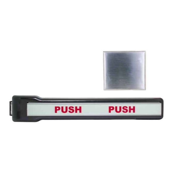
- Page 4 Label - D Panic Device Base Completely Assembled Component Parts List Letter Part Panic Device Cover Base Plate Panic Device Base Push Label Exterior Trim Plate Exterior Trim Plate - E LKM10KPEINST Copyright Lockmasters, Inc. 2018 February 2018 Version A...
-
Page 5: Tools Needed
LKM10K Exit Only Exterior Trim Mounting Template 10-24 Tap & Handle with #25 Drill Bit Part Number: 10KEEOTMP Masking Tape REV E Sharpie or Pencil 1/4 Philips Bit Philips Screwdriver Flat Scresdriver Wire Strippers LKM10KPEINST Copyright Lockmasters, Inc. 2018 February 2018 Version A... - Page 6 Trim side of the door with the combination square at least 10”. Confirm accuracy with level. 2b- Extend Horizontal line to door’s edge 2c- Continue Horizontal line to Exterior Trim side at least 10” across the door. LKM10KPEINST Copyright Lockmasters, Inc. 2018 February 2018 Version A...
- Page 7 You will see a gap between the door and combination square. (See Figure 2) Figure 2 - Establishing the high side of a bevel edged door. LKM10KPEINST Copyright Lockmasters, Inc. 2018 February 2018 Version A...
- Page 8 (See large red circle in figure 4) "B" "B" 7/16” 7/16” 8 " LOCKMASTERS, INC. LKM10K Exit Only Exterior Trim Mounting Template Part Number: 10KEEOTMP Figure 4 - Sample Template REV E LKM10KPEINST Copyright Lockmasters, Inc. 2018 February 2018 Version A...
- Page 9 6d – Move to the Panic Device side of the door and repeat. 6d- Tape template above the punched holes and mark hole diameters & letter for easy reference LKM10KPEINST Copyright Lockmasters, Inc. 2018 February 2018 Version A...
-
Page 10: Drilling The Holes
Exterior Trim/Panic Base Plate Attaching Holes. 9a METAL DOOR – Drill the 4 (B) Exterior Trim Attaching Holes – Use a 7/16” metal cutting hole saw and drill through the outer skin. LKM10KPEINST Copyright Lockmasters, Inc. 2018 February 2018 Version A... - Page 11 Exterior Trim Plate into position. (Figure 5) Front Plate Offsets Door Edge The short offset side of the Front Plate goes toward the door’s edge. 11a - Exterior Trim will sit flush against the door LKM10KPEINST Copyright Lockmasters, Inc. 2018 February 2018 Version A...
- Page 12 13d & e - With pressure on wrench tighten screw 13g - Repeat steps 13a - 13f on the remaining (3) C2 holes. 13f - Jack Nut firmly seated, screw removed LKM10KPEINST Copyright Lockmasters, Inc. 2018 February 2018 Version A...
- Page 13 Thread Locker 15b - Exterior Trim secured to the door. 15b - Permanently attach the Exterior Trim to the door through the Base Plate. LKM10KPEINST Copyright Lockmasters, Inc. 2018 February 2018 Version A...
- Page 14 - Insert the (4) metal thread forming screws 1/4” hex head machine screws and install into into the (4) remaining C holes and loosely the last two C2 holes (rear most end) tighten. LKM10KPEINST Copyright Lockmasters, Inc. 2018 February 2018 Version A...
- Page 15 18a - Slide the Panic Device Cover over the 18b - Secure with the (10) 3-32 flat head screws installed Panic Device Base Assembly using the supplied Hex Ball Driver. LKM10KPEINST Copyright Lockmasters, Inc. 2018 February 2018 Version A...
- Page 16 19h - Drill Pilot Holes in the remaining (3) strike 19i & j - Apply Thread Locker to strike screws and holes and tap. attach strike. Remove the (2) previously installed screws, apply Thread Locker and re-install LKM10KPEINST Copyright Lockmasters, Inc. 2018 February 2018 Version A...
Need help?
Do you have a question about the LOCKONE LKM10K and is the answer not in the manual?
Questions and answers